Page 3499 of 4264
FRONT SUSPENSION 3C-7
4
�
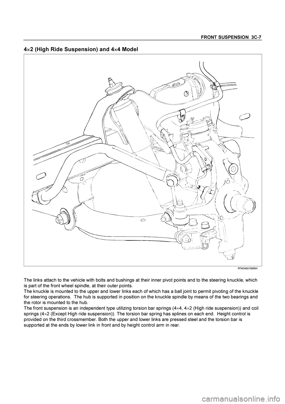
�� �2 (High Ride Suspension) and 4
�
�� �4 Model
RTW340LF000801
The links attach to the vehicle with bolts and bushings at their inner pivot points and to the steering knuckle, which
is part of the front wheel spindle, at their outer points.
The knuckle is mounted to the upper and lower links each of which has a ball joint to permit pivoting of the knuckle
for steering operations. The hub is supported in position on the knuckle spindle by means of the two bearings and
the rotor is mounted to the hub.
The front suspension is an independent type utilizing torsion bar springs (4�
4, 4�
2 (High ride suspension)) and coil
springs (4�
2 (Except High ride suspension)). The torsion bar spring has splines on each end. Height control is
provided on the third crossmember. Both the upper and lower links are pressed steel and the torsion bar is
supported at the ends by lower link in front and by height control arm in rear.
Page 3509 of 4264
FRONT SUSPENSION 3C-17
Knuckle
Knuckle and Associated Parts
450R300037
Legend
(1)
Nut and Cotter Pin
(2)
Back Plate
(3)
Nut and Cotter Pin
(4)
Nut and Cotter Pin
(5)
Knuckle
(6)
Bolt
Removal
1. Raise the vehicle and support the frame with
suitable safety stands.
2. Remove wheel and tire assembly. Refer to Wheel
in this section.
3. Remove the brake caliper. Refer to Disc Brakes in
Brake section.
4. Remove the hub assembly. Refer to Front Hub
and Disk in this section.
5. Remove tie-rod end from the knuckle. Refer to
Power Steering Unit in Steering section.
Page 3513 of 4264
FRONT SUSPENSION 3C-21
Lower Control Arm
Lower Control Arm and Associated Parts
RTW340LF002301
Legend
(1)
Cam bolt
(2)
Bush
(3)
Cam plate
(4)
Nut
(5)
Nut
(6)
Bolt
(7)
Lower Ball Joint
(8)
Nut and cotter pin
(9)
Nut
(10) Nut
(11) Bolt
Removal
1. Raise the vehicle and support the frame with
suitable safety stands.
2. Remove wheel and tire assembly. Refer to Wheel
in this section.
3. Remove the tie-rod end from the knuckle. Refer to
Power Steering Unit in Steering section.
Page 3537 of 4264

FRONT SUSPENSION 3C-45
Removal
1. Raise the vehicle and support the frame with
suitable safety stands.
2. Remove wheel and tire assembly. Refer to Wheel
in this section.
3. Remove the tie-rod end from the knuckle. Refer to
Power Steering Unit in Steering section.
4. Remove the retaining ring from the front axle
driving shaft to release the shaft from hub. Refer to
Front Hub and Disc in Driveline/Axle section.
5. Support lower control arm with a jack.
6. Remove cam plate and nut.
7. Remove rear nut.
8. Remove torsion bar, refer to Torsion Bar in this
section.
9. Remove torsion bar arm bracket.
10. Disconnect the stabilizer link at the lower control
arm.
11. Remove the shock absorber lower end from the
lower control arm.
12. Remove the lower ball joint from the lower control
arm.
13. Remove cam bolt.
14. Remove rear bolt.
15. Remove lower control arm.
16. Remove torsion bar arm bolt.
17. Remove lower ball joint bolt.
18. Remove front bushing by using remover 5-8840-
2123-0.
Front
901RW154
Front
901RW155
19. Remove rear bushing by using remover 5-8840-
2124-0.
Front
901RW051
Front
901RW052
Page 3542 of 4264
3C-50 FRONT SUSPENSION
Lower Ball Joint
Lower Ball Joint and Associated Parts
RTW340LF001601
Legend
(1)
Bolt
(2)
Lower Ball Joint
(3) Nut
(4)
Nut and Cotter Pin
Removal
1. Raise the vehicle and support the frame with
suitable safety stands.
2. Remove wheel and tire assembly. Refer to Wheel
in this section.
3. Remove the tie-rod end from the knuckle. Refer to
Power Steering Unit in Steering section.
4. Remove the retaining ring from the front axle
driving shaft to release the shaft from hub. Refer to
Front Hub and Disc in Driveline/Axle section.
5. Support lower control arm with a jack.
6. Remove lower ball joint nut and cotter pin, then
use remover 5-8840-2005-0 to remove the lowe
r
ball joint from the knuckle.
Page 3546 of 4264

3C-54 FRONT SUSPENSION
TROUBLESHOOTING
1. VIBRATION, SHOCK, AND SHIMMY OF STEERING WHEEL
Checkpoint Trouble Cause Countermeasure
Check front axle
Check wheel alignment
Check suspension ball joint
Check shock absorber or
attaching nut and bolt
Replace
Adjust
Replace
Replace or retighten
Check steering unit and
linkage
Faulty
Worn
Malfunction or loose
Check upper and lower link
bushings
Replace
Adjust
Worn
Incorrect
OK OK OK
NG NG NG NG NG NG
OK OK
Check vehicle trim height
�
Improperly adjusted or worn front
wheel bearing.
�
Worn or incorrectl
y adjusted wheel
bearing.
Replace; refer to Section 4C "Front
Wheel Drive"
�
Insufficientl
y tightened steeringgear housing.
�
Wear of steering linkage.
�
Excessive backlash due to
improper ad
justment of the steeringgear box.
� Worn column bearing weakened
column bearing spring, or loose
clamp.
Replace; refer to Section 3B
"Steering"
�
Improper tire pressure.
� Imbalance and deformation of frond
wheel.
�
Unevenl
y worn tire or insufficient
tightening of wheel nuts.
Replace; refer to Section 3E "Wheel
and Tires"
Page 3547 of 4264
FRONT SUSPENSION 3C-55
2. VEHICLE PULLS TO RIGHT OR LEFT
Checkpoint Trouble Cause Countermeasure
Steering linkage, and upper
and lower link
Rubber bushing for upper and
lower link
Wheel alignment
Vehicle trim height
Replace
Replace
Adjust
Adjust
Deformed
Worn
Incorrect
Incorrect
Brake adjustment (binding)
Adjust
Replace
Incorrect
Collapsed or break (4�
2
Except high ride suspension)
Collapsed or twisted (4�
4, 4�
2
High ride suspension)
Continued on the next pageOK OK OK OK
NG NG NG NG NG NG
OK OK Coil spring (4�2 Except high
ride suspension)
Torsion bar (4�
4, 4�
2 High
ride suspension)
Front wheel bearing
Adjust or replace
Incorrect adjustment or
abrasion
NG
Page 3549 of 4264
FRONT SUSPENSION 3C-57
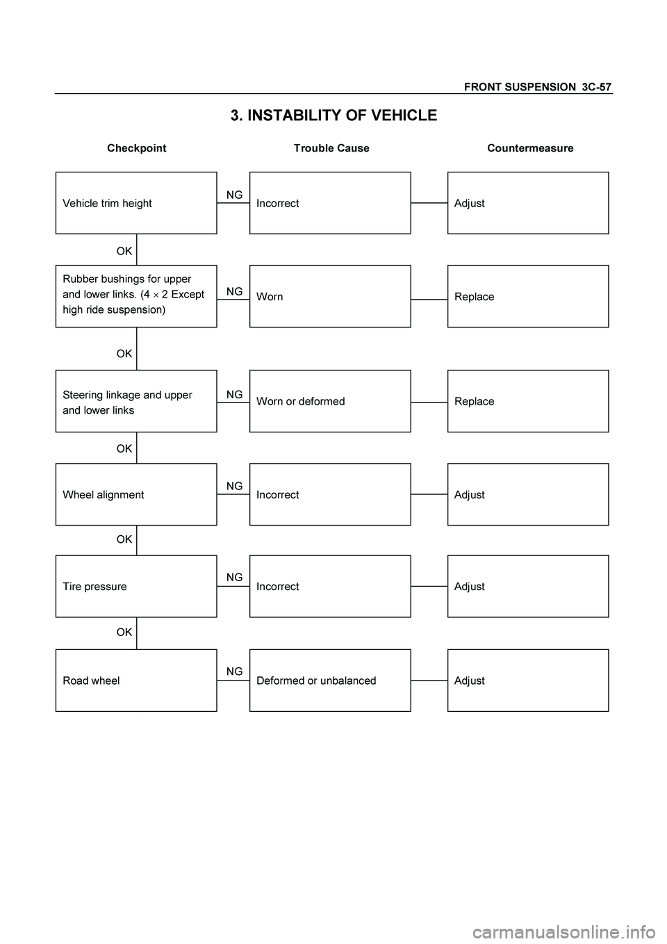
3. INSTABILITY OF VEHICLE
Checkpoint Trouble Cause Countermeasure
Tire pressure
Wheel alignment
Rubber bushings for upper
and lower links. (4 � 2 Except
high ride suspension)
Adjust
Adjust
Replace
Incorrect
Incorrect
Worn
Steering linkage and upper
and lower links
Replace
Adjust
Worn or deformed
Incorrect
OK OK OK
NG NG NG NG NG
OK OK
Vehicle trim height
Road wheel
Adjust
Deformed or unbalanced
NG

Nut and Cotter Pin
(2)
Back Plate
(3)
Nut and Cotter Pin
(4)
Nut and Cotter Pin
(5)")

Cam bolt
(2)
Bush
(3)
Cam plate
(4)
Nut
(5)
Nut
(6)
Bolt")

Bolt
(2)
Lower Ball Joint
(3) Nut
(4)
Nut and Cotter Pin
Rem")