Page 2263 of 3371
IP-18
INSTRUMENT PANEL ASSEMBLY
Revision: August 20072004 QX56
1. Remove cup holder insert.
2. Release latch and remove rear console assembly.
3. Remove hinge cover.
4. Remove screws from hinge assembly and remove console lid assembly.
�Remove hinge from upper console assembly.
�Remove latch from lid assembly.
5. Remove screws and separate upper and lower console assemblies.
�Remove floor latch from upper console assembly.
6. Remove screws and remove bin from upper console assembly.
7. Remove screws and remove floor base.
8. Remove bolts and remove floor bracket.
Assembly is in the reverse order of disassembly.
Page 2495 of 3371
LT-64
AUTO LIGHT SYSTEM
Revision: August 20072004 QX56
Removal and Installation of Optical SensorEKS007B3
REMOVAL
1. Remove defrost grille. Refer to IP-10, "INSTRUMENT PANEL ASSEMBLY" .
2. Disconnect the connector.
3. Turn the optical sensor counterclockwise to remove it from
defroster grille.
INSTALLATION
Installation is in the reverse order of removal.
WKIA1061E
Page 2499 of 3371
LT-68
HEADLAMP AIMING CONTROL
Revision: August 20072004 QX56
Removal and InstallationEKS007TM
1. Remove cluster lid A. Refer to IP-10, "INSTRUMENT PANEL ASSEMBLY" .
2. Carefully release the headlamp aiming switch retaining pawls
and remove the switch.
Switch Circuit InspectionEKS007TN
Using a circuit tester, check continuity between the headlamp aiming
switch connector terminals in each operation status of the aiming
switch.
WKIA1879E
Resistor tolerance : ±5%
WKIA1882E
Page 2637 of 3371
MA-20
CHASSIS AND BODY MAINTENANCE
Revision: August 20072004 QX56
CHASSIS AND BODY MAINTENANCEPFP:00100
Changing In-cabin MicrofilterELS0010E
1. Remove the instrument lower cover RH.
2. Remove the glove box assembly.
a. Remove the two lower glove box screws.
b. Open the glove box, then remove the four upper glove box
screws.
NOTE:
It is not necessary to remove the two glove box striker screws.
c. Remove the glove box assembly from the instrument panel to
access the in-cabin microfilter cover.
3. Remove the screw and remove the in-cabin microfilter cover.
4. Remove the in-cabin microfilters from the front heater and cool-
ing unit assembly housing.
LLIA0072E
LJIA0146E
WJIA0628E
LJIA0134E
Page 2638 of 3371

CHASSIS AND BODY MAINTENANCE
MA-21
C
D
E
F
G
H
I
J
K
MA
B
MA
Revision: August 20072004 QX56
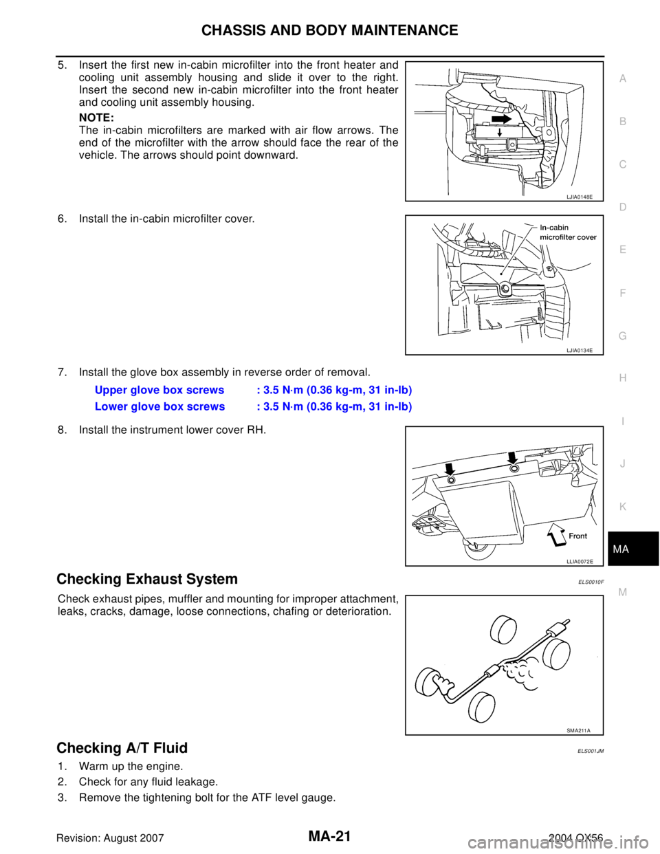
5. Insert the first new in-cabin microfilter into the front heater and
cooling unit assembly housing and slide it over to the right.
Insert the second new in-cabin microfilter into the front heater
and cooling unit assembly housing.
NOTE:
The in-cabin microfilters are marked with air flow arrows. The
end of the microfilter with the arrow should face the rear of the
vehicle. The arrows should point downward.
6. Install the in-cabin microfilter cover.
7. Install the glove box assembly in reverse order of removal.
8. Install the instrument lower cover RH.
Checking Exhaust SystemELS0010F
Check exhaust pipes, muffler and mounting for improper attachment,
leaks, cracks, damage, loose connections, chafing or deterioration.
Checking A/T FluidELS001JM
1. Warm up the engine.
2. Check for any fluid leakage.
3. Remove the tightening bolt for the ATF level gauge.
LJIA0148E
LJIA0134E
Upper glove box screws : 3.5 N·m (0.36 kg-m, 31 in-lb)
Lower glove box screws : 3.5 N·m (0.36 kg-m, 31 in-lb)
LLIA0072E
SM A211 A
Page 2652 of 3371

PARKING BRAKE SYSTEM
PB-3
C
D
E
G
H
I
J
K
L
MA
B
PB
Revision: August 20072004 QX56
PARKING BRAKE SYSTEMPFP:36010
On-Vehicle ServiceEFS003Q4
PEDAL STROKE
�When parking brake pedal is operated with the specified force, make sure the stroke is within the specified
number of notches. Check by listening and counting the ratchet clicks.
INSPECTION
�Make sure the components are attached properly, checking for looseness or backlash.
�Check parking brake pedal assembly for bends, damage and cracks, and replace if necessary.
�Check cable for wear and damage, and replace if necessary.
�Check parking brake warning lamp switch for malfunction, and replace if necessary. Refer to DI-32, "Wir-
ing Diagram — WARN —" .
ADJUSTMENT
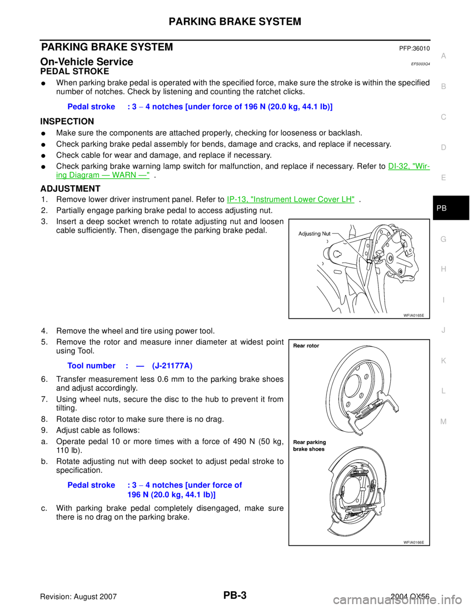
1. Remove lower driver instrument panel. Refer to IP-13, "Instrument Lower Cover LH" .
2. Partially engage parking brake pedal to access adjusting nut.
3. Insert a deep socket wrench to rotate adjusting nut and loosen
cable sufficiently. Then, disengage the parking brake pedal.
4. Remove the wheel and tire using power tool.
5. Remove the rotor and measure inner diameter at widest point
using Tool.
6. Transfer measurement less 0.6 mm to the parking brake shoes
and adjust accordingly.
7. Using wheel nuts, secure the disc to the hub to prevent it from
tilting.
8. Rotate disc rotor to make sure there is no drag.
9. Adjust cable as follows:
a. Operate pedal 10 or more times with a force of 490 N (50 kg,
11 0 l b ) .
b. Rotate adjusting nut with deep socket to adjust pedal stroke to
specification.
c. With parking brake pedal completely disengaged, make sure
there is no drag on the parking brake.Pedal stroke : 3 − 4 notches [under force of 196 N (20.0 kg, 44.1 lb)]
WFIA0165E
Tool number : — (J-21177A)
Pedal stroke : 3 − 4 notches [under force of
196 N (20.0 kg, 44.1 lb)]
WFIA0166E
Page 2653 of 3371

PB-4
PARKING BRAKE CONTROL
Revision: August 20072004 QX56
PARKING BRAKE CONTROLPFP:36010
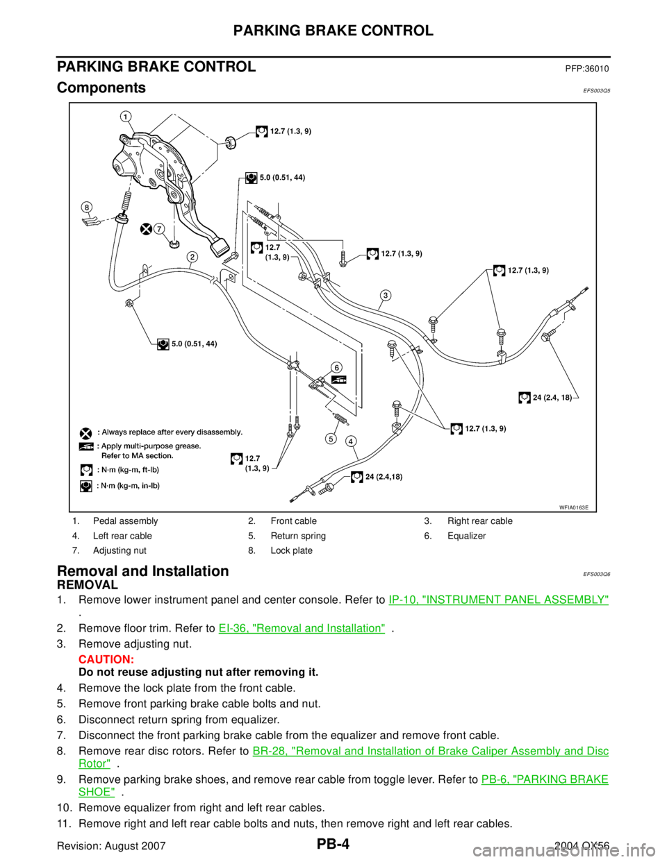
ComponentsEFS003Q5
Removal and InstallationEFS003Q6
REMOVAL
1. Remove lower instrument panel and center console. Refer to IP-10, "INSTRUMENT PANEL ASSEMBLY"
.
2. Remove floor trim. Refer to EI-36, "
Removal and Installation" .
3. Remove adjusting nut.
CAUTION:
Do not reuse adjusting nut after removing it.
4. Remove the lock plate from the front cable.
5. Remove front parking brake cable bolts and nut.
6. Disconnect return spring from equalizer.
7. Disconnect the front parking brake cable from the equalizer and remove front cable.
8. Remove rear disc rotors. Refer to BR-28, "
Removal and Installation of Brake Caliper Assembly and Disc
Rotor" .
9. Remove parking brake shoes, and remove rear cable from toggle lever. Refer to PB-6, "
PARKING BRAKE
SHOE" .
10. Remove equalizer from right and left rear cables.
11. Remove right and left rear cable bolts and nuts, then remove right and left rear cables.
1. Pedal assembly 2. Front cable 3. Right rear cable
4. Left rear cable 5. Return spring 6. Equalizer
7. Adjusting nut 8. Lock plate
WFIA0163E
Page 2760 of 3371
TILT SYSTEM
PS-9
C
D
E
F
H
I
J
K
L
MA
B
PS
Revision: August 20072004 QX56
TILT SYSTEMPFP:48810
Removal and InstallationEGS000N8
TILT MOTOR AND TILT SENSOR
Removal
1. Remove the steering column cover and lower driver instrument panel. Refer to IP-10, "INSTRUMENT
PANEL ASSEMBLY" .
2. Remove knee protector.
3. Disconnect the tilt sensor electrical connector.
4. Remove the two tilt sensor screws and the tilt sensor.
5. Disconnect the tilt motor electrical connector.
6. Remove the tilt motor bolt and the tilt motor.
Installation
Installation is in reverse order of removal.
NOTE:
Make sure the tab in the tilt sensor is engaged in the bracket on the tilt motor.
LGIA0022E
1. Tilt sensor 2. Tilt motor
LGIA0026E