Page 2907 of 3371
RSU-48
SERVICE DATA AND SPECIFICATIONS (SDS)
Revision: August 20072004 QX56
Wheelarch Height (Unladen*1 )EES0011Z
Unit: mm (in)
*1: Fuel, engine coolant and engine oil full. Spare tire, jack, hand tools and mats in designated positions.
*2: Verify the vehicle height using Consult-II memory register 1103 and set rear wheelarch height to 0 ± 10 mm (0 ± 0.39 in) as neces-
sary.Suspension type
Air leveling*
2
Applied model4x2 4x4
Front wheelarch height (Hf)913
(35.94)931
(36.65)
Rear wheelarch height (Hr)912
(35.91)932
(36.69)
LEIA0085E
Page 3280 of 3371

WT-1
ROAD WHEELS & TIRES
E SUSPENSION
CONTENTS
C
D
F
G
H
I
J
K
L
M
SECTION WT
A
B
WT
Revision: August 20072004 QX56 PREPARATION ........................................................... 2
Special Service Tool ................................................. 2
Commercial Service Tools ........................................ 2
NOISE, VIBRATION, AND HARSHNESS (NVH)
TROUBLESHOOTING ................................................ 3
NVH Troubleshooting Chart ..................................... 3
WHEEL ....................................................................... 4
Inspection ................................................................. 4
WHEEL AND TIRE ASSEMBLY ................................. 5
Balancing Wheels .................................................... 5
REMOVAL ............................................................. 5
WHEEL BALANCE ADJUSTMENT ...................... 5
Rotation .................................................................... 6
LOW TIRE PRESSURE WARNING SYSTEM ............ 7
System Components ................................................ 7
System Description .................................................. 7
TRANSMITTER ..................................................... 7
REMOTE KEYLESS ENTRY RECEIVER ............. 7
BCM (BODY CONTROL MODULE) ...................... 8
LOW TIRE PRESSURE WARNING LAMP AND
BUZZER ................................................................ 8
DISPLAY UNIT ...................................................... 8
CAN COMMUNICATION ............................................ 9
System Description .................................................. 9
TROUBLE DIAGNOSES .......................................... 10
Wiring Diagram — T/WARN — .............................. 10
Terminal and Reference Value (BCM) .................... 12
ID Registration Procedure ...................................... 13
ID REGISTRATION WITH TRANSMITTER
ACTIVATION TOOL ............................................ 13
ID REGISTRATION WITHOUT TRANSMITTER
ACTIVATION TOOL ............................................ 14
Transmitter Wake Up Operation ............................. 15
............................................................................ 15
CONSULT-II Function (BCM) ................................. 16
Self-Diagnosis ........................................................ 17
DESCRIPTION .................................................... 17
FUNCTION .......................................................... 17CONSULT-II ......................................................... 17
How to Perform Trouble Diagnosis for Quick and
Accurate Repair ...................................................... 19
INTRODUCTION ................................................. 19
WORK FLOW ...................................................... 19
Preliminary Check .................................................. 20
Malfunction Code/Symptom Chart .......................... 21
TROUBLE DIAGNOSIS FOR SELF-DIAGNOSTIC
ITEMS ........................................................................ 23
Inspection 1: Transmitter or Control Unit (BCM) ..... 23
MALFUNCTION CODE NO. 21, 22, 23 OR 24 ... 23
Inspection 2: Transmitter - 1 ................................... 23
MALFUNCTION CODE NO. 31, 32, 33, 34, 41,
42, 43, 44, 45, 46, 47 OR 48 ............................... 23
Inspection 3: Transmitter - 2 ................................... 24
MALFUNCTION CODE NO. 35, 36, 37 OR 38 ... 24
Inspection 4: Vehicle Speed Signal ........................ 25
MALFUNCTION CODE NO. 52 ........................... 25
TROUBLE DIAGNOSIS FOR SYMPTOMS .............. 26
Inspection 1: Low Tire Pressure Warning Lamp
Does Not Come On When Ignition Switch Is Turned
On ........................................................................... 26
Inspection 2: Low Tire Pressure Warning Lamp
Stays On When Ignition Switch Is Turned On ......... 26
Inspection 3: Low Tire Pressure Warning Lamp
Flashes When Ignition Switch Is Turned On .......... 28
Inspection 4: Hazard Warning Lamp Flashes When
Ignition Switch Is Turned On .................................. 29
Inspection 5: “TIRE PRESSURE” Information In
Display Unit Does Not Exist .................................... 30
Inspection 6: ID Registration Cannot Be Completed ... 30
REMOVAL AND INSTALLATION ............................. 31
Transmitter (Pressure Sensor) ............................... 31
REMOVAL ........................................................... 31
INSTALLATION ................................................... 31
SERVICE DATA AND SPECIFICATIONS (SDS) ...... 33
Road Wheel ............................................................ 33
Tire ......................................................................... 33
Page 3282 of 3371

NOISE, VIBRATION, AND HARSHNESS (NVH) TROUBLESHOOTING
WT-3
C
D
F
G
H
I
J
K
L
MA
B
WT
Revision: August 20072004 QX56
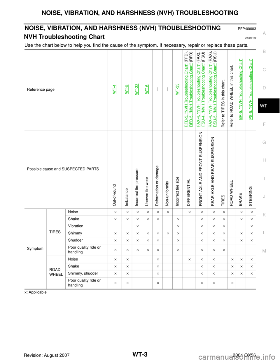
NOISE, VIBRATION, AND HARSHNESS (NVH) TROUBLESHOOTINGPFP:00003
NVH Troubleshooting ChartEES00122
Use the chart below to help you find the cause of the symptom. If necessary, repair or replace these parts.
×: ApplicableReference page
WT-4WT-5WT-33WT-6—
—
WT-33
RFD-5, "
NVH Troubleshooting Chart
" (FFD),
RFD-5, "
NVH Troubleshooting Chart
" (RFD)
FAX -4, "
NVH Troubleshooting Chart
" (FAX),
FSU-4, "
NVH Troubleshooting Chart
" (FSU)
RAX-4, "
NVH Troubleshooting Chart
" (RAX),
RSU-5, "
NVH Troubleshooting Chart
" (RSU)
Refer to TIRES in this chart.
Refer to ROAD WHEEL in this chart.
BR-5, "
NVH Troubleshooting Chart
"
PS-5, "
NVH Troubleshooting Chart
"
Possible cause and SUSPECTED PARTS
Out-of-round
Imbalance
Incorrect tire pressure
Uneven tire wear
Deformation or damage
Non-uniformity
Incorrect tire size
DIFFERENTIAL
FRONT AXLE AND FRONT SUSPENSION
REAR AXLE AND REAR SUSPENSION
TIRES
ROAD WHEEL
BRAKE
STEERING
SymptomTIRESNoise× ××××× × × × × ××
Shake××××× × ××× ××
Vibration××××××
Shimmy× ×××××× × × × ××
Shudder××××× × ××× ××
Poor quality ride or
handling××××× × ×××
ROAD
WHEELNoise×× × ××× ×××
Shake×× × ×× ×××
Shimmy, shudder×× × ×× ×××
Poor quality ride or
handling×× × ×× ×