Page 500 of 3371
 POWER SUPPLY CIRCUIT
1. Turn ignition switch OFF.
2. Disconnect fuse bl")
TROUBLE DIAGNOSIS
ATC-95
C
D
E
F
G
H
I
K
L
MA
B
AT C
Revision: August 20072004 QX56
6. CHECK REAR BLOWER MOTOR RELAY (COIL SIDE) POWER SUPPLY CIRCUIT
1. Turn ignition switch OFF.
2. Disconnect fuse block (J/B) connector M39.
3. Turn ignition switch ON.
4. Set rear fan switch (front) to any position except off (0), rear (R),
or 4 - speed.
5. Check voltage between fuse block (J/B) harness connector M39
terminal 3Q (W/L) and ground.
OK or NG
OK >> GO TO 7.
NG >> GO TO 20.
7. CHECK REAR BLOWER MOTOR RELAY (COIL SIDE) GROUND CIRCUIT
1. Turn ignition switch OFF.
2. Disconnect fuse block (J/B) connector M3.
3. Check continuity between fuse block (J/B) harness connector
M3 terminal 7N (B) and ground.
OK or NG
OK >> Replace fuse block (J/B).
NG >> Repair harness or connector.
8. REPLACE FUSE
Refer to PG-76, "
FUSE BLOCK-JUNCTION BOX(J/B)" .
Fuse should not open when rear blower motor is activated.
OK or NG
OK >> Inspection End.
NG >> GO TO 9.
9. CHECK REAR BLOWER MOTOR POWER SUPPLY CIRCUIT FOR SHORT
1. Turn ignition switch OFF.
2. Disconnect battery cables and rear blower motor connector
B134.
3. Check continuity between rear blower motor harness connector
B134 terminal 2 (L/R) and ground.
OK or NG
OK >> Check rear blower motor. Refer to ATC-100, "Rear
Blower Motor" .
NG >> Repair harness or connector.1 - Ground : Battery voltage should exist.
LJIA0101E
7N - Ground : Continuity should exist.
WJIA0597E
2 - Ground : Continuity should not exist.
WJIA0598E
Page 503 of 3371
ATC-98
TROUBLE DIAGNOSIS
Revision: August 20072004 QX56
18. CHECK REAR FAN SWITCH (FRONT)
Refer to ATC-99, "
Rear Fan Switch (Front)" .
OK or NG
OK >> GO TO 19.
NG >> Replace rear fan switch (front). Refer to ATC-135, "
FRONT AIR CONTROL" .
19. CHECK REAR FAN SWITCH (REAR)
Refer to ATC-99, "
Rear Fan Switch (Rear)" .
OK or NG
OK >> Inspection End.
NG >> Replace rear fan switch (rear). Refer to ATC-135, "
REAR AIR CONTROL" .
20. CHECK CIRCUIT BETWEEN FRONT AIR CONTROL AND FUSE BLOCK (J/B) [REAR BLOWER
MOTOR RELAY (COIL SIDE) POWER]
1. Disconnect front air control connector M50 and fuse block (J/B)
connector M39.
2. Check continuity between front air control harness connector
M50 terminal 38 (W/L) and fuse block (J/B) connector M39 ter-
minal 3Q (W/L).
OK or NG
OK >> Replace front air control. Refer to ATC-135, "FRONT
AIR CONTROL"
NG >> Repair harness or connector.38 - 3Q : Continuity should exist.LJ IA 0 111E
Page 504 of 3371
TROUBLE DIAGNOSIS
ATC-99
C
D
E
F
G
H
I
K
L
MA
B
AT C
Revision: August 20072004 QX56
COMPONENT INSPECTION
Rear Blower Motor Relay
Check circuit continuity between terminals by supplying 12 volts and
ground to coil side terminals of relays.
Rear Fan Switch (Rear)
Check continuity between terminals at each switch position.
Rear Fan Switch (Front)
Check continuity between terminals at each switch position.
WJIA0896E
WJIA0800E
WJIA0897E
Page 529 of 3371
ATC-124
TROUBLE DIAGNOSIS
Revision: August 20072004 QX56
COMPONENT INSPECTION
Water Valve R elay
Check continuity between terminals by supplying 12 volts and
ground to coil side terminals of relay.
WJIA0899E
Page 551 of 3371

ATC-146
HEATER & COOLING UNIT ASSEMBLY
Revision: August 20072004 QX56
4. Remove the exhaust system. Refer to EX-3, "Removal and Installation" .
5. Disconnect the front heater hoses from the front heater core.
6. Disconnect the high/low pressure pipes from the front expansion valve.
7. Move the two front seats to the rearmost position on the seat track.
8. Remove the instrument panel and console panel. Refer to IP-10, "
INSTRUMENT PANEL ASSEMBLY" .
9. Remove the steering column. Refer to PS-10, "
Removal and Installation" .
10. Disconnect the instrument panel wire harness at the RH and LH in-line connector brackets, and the fuse
block (J/B) electrical connectors. Refer to PG-40, "
Harness Layout" .
11. Disconnect the steering member from each side of the vehicle body.
12. Remove the front heater and cooling unit assembly with it attached to the steering member, from the vehi-
cle.
CAUTION:
Use care not to damage the seats and interior trim panels when removing the front heater and
cooling unit assembly with it attached to the steering member.
13. Remove the front heater and cooling unit assembly from the steering member.
Installation
Installation is in the reverse order of removal.
CAUTION:
�Replace the O-ring of the low-pressure pipe and high-pressure pipe with a new one, and apply
compressor oil to it when installing it.
�After charging the refrigerant, check for leaks.
NOTE:
�Fill the engine cooling system with the specified coolant mixture. Refer to MA-13, "REFILLING ENGINE
COOLANT" .
�Recharge the A/C system. Refer to ATC-162, "Evacuating System and Charging Refrigerant" .
REAR HEATER AND COOLING UNIT ASSEMBLY
Removal
1. Discharge the refrigerant from the A/C system. Refer to ATC-162, "Discharging Refrigerant" .
2. Drain the coolant from the engine cooling system. Refer to MA-12, "
DRAINING ENGINE COOLANT" .
3. Disconnect the rear heater core hoses from the rear heater core.
4. Disconnect the rear A/C pipes from the rear expansion valve.
5. Remove the rear RH interior trim panel. Refer to EI-34,
"Removal and Installation" .
6. Disconnect the following electrical connectors:
�Rear blower motor
�Rear blower motor resistor
�Rear air mix door motor
7. Disconnect the ducts from the rear heater and cooling unit
assembly.
8. Remove the rear heater and cooling unit assembly.
Installation
Installation is in the reverse order of removal.
CAUTION:
�Replace the O-ring of the low-pressure pipe and high-pressure pipe with a new one, and apply
compressor oil to it when installing it.
�After charging the refrigerant, check for leaks.
NOTE:
�Fill the engine cooling system with the specified coolant mixture. Refer to MA-13, "REFILLING ENGINE
COOLANT" .
�Recharge the A/C system. Refer to ATC-162, "Evacuating System and Charging Refrigerant" .
LJIA0021E
Page 572 of 3371
REFRIGERANT LINES
ATC-167
C
D
E
F
G
H
I
K
L
MA
B
AT C
Revision: August 20072004 QX56
INSTALLATION
Installation is in the reverse order of removal.
CAUTION:
�Replace the O-ring of the low-pressure flexible hose and high-pressure flexible hose with a new
one, apply compressor oil to the O-rings before installation.
�After recharging the A/C system with refrigerant, check for leaks.
Removal and Installation for Compressor ClutchEJS002DK
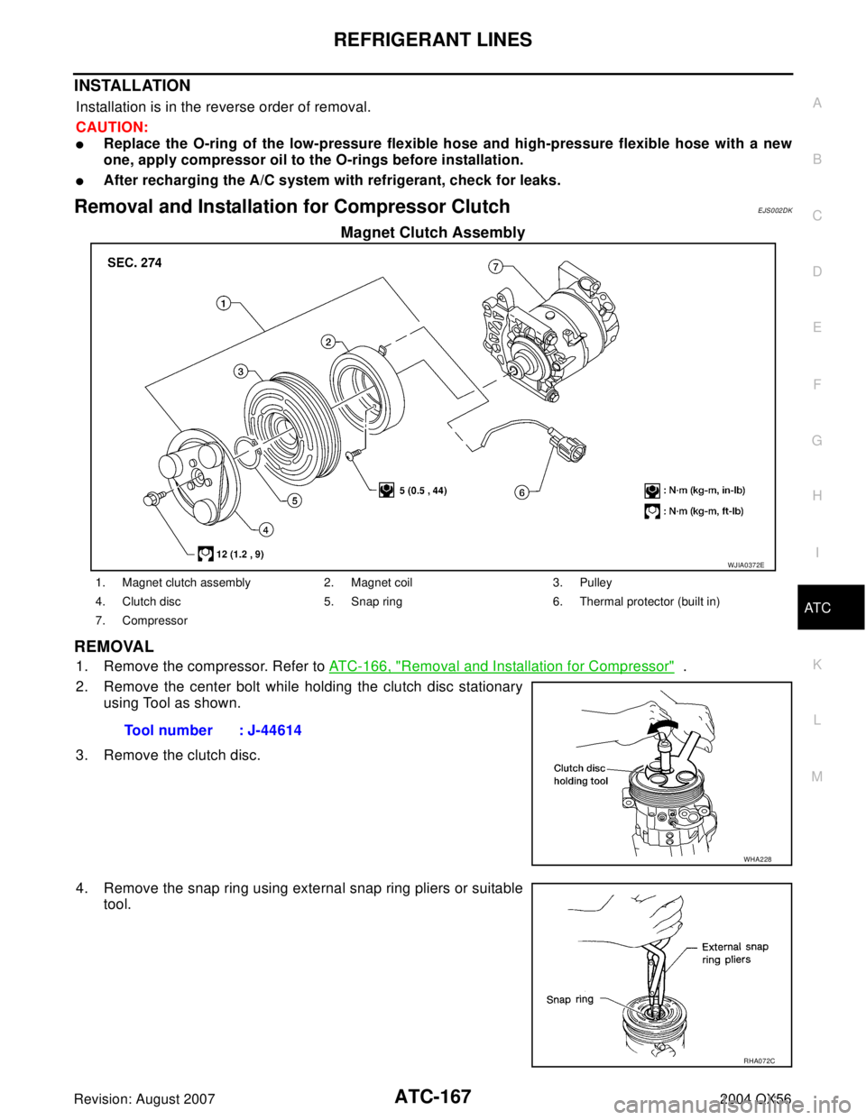
Magnet Clutch Assembly
REMOVAL
1. Remove the compressor. Refer to ATC-166, "Removal and Installation for Compressor" .
2. Remove the center bolt while holding the clutch disc stationary
using Tool as shown.
3. Remove the clutch disc.
4. Remove the snap ring using external snap ring pliers or suitable
tool.
WJIA0372E
1. Magnet clutch assembly 2. Magnet coil 3. Pulley
4. Clutch disc 5. Snap ring 6. Thermal protector (built in)
7. Compressor
Tool number : J-44614
WHA228
RHA072C
Page 573 of 3371

ATC-168
REFRIGERANT LINES
Revision: August 20072004 QX56
5. Remove the pulley using Tool with a small adapter. Position the
small adapter on the end of the drive shaft and the center of the
puller on the small adapter.
CAUTION:
To prevent deformation of the pulley groove, the puller
claws should be hooked under the pulley groove and not
into the pulley groove.
6. Remove the magnet coil harness clip using a screwdriver,
remove the three magnet coil fixing screws and remove the
magnet coil.
INSPECTION
Clutch Disc
If the contact surface shows signs of damage due to excessive heat,
replace clutch disc and pulley.
Pulley
Check the appearance of the pulley assembly. If contact surface of pulley shows signs of excessive grooving,
replace clutch disc and pulley. The contact surfaces of the pulley assembly should be cleaned with a suitable
solvent before reinstallation.
Coil
Check magnet coil for loose connections or any cracked insulation.
INSTALLATION
1. Install the magnet coil.
CAUTION:
Be sure to align the magnet coil pin with the hole in the
compressor front head.
LHA173
WHA212
WHA183
WHA213
Page 574 of 3371

REFRIGERANT LINES
ATC-169
C
D
E
F
G
H
I
K
L
MA
B
AT C
Revision: August 20072004 QX56
2. Install the magnet coil harness clip using a screwdriver.
3. Install the pulley assembly using Tool and a wrench, then install
the snap ring using snap ring pliers.
4. Install the clutch disc on the compressor shaft, together with the
original shim(s). Press the clutch disc down by hand.
5. Install the clutch pulley bolt using Tool, to prevent the clutch disc
from turning and tighten the bolt to specification. Refer to AT C -
164, "Components" .
CAUTION:
After tightening the clutch pulley bolt, check that the clutch
pulley rotates smoothly.
6. Check the pulley clearance all the way around the clutch disc as
shown.
7. If the specified clearance is not obtained, replace the adjusting
spacer to readjust.
8. Connect the compressor electrical connector.
9. Install the drive belt. Refer to EM-13, "
Installation" .
10. Install the engine under cover and the splash shield.Tool number : — (J-38873-A)
WJIA0368E
WHA184
Tool number : J-44614
WHA229
Clutch disc-to-pulley clearance : 0.3 - 0.6 mm
(0.012 - 0.024 in)
WHA194

Refer to ATC-99, \"
Rear Fan Switch (Front)\" .
OK or NG
OK >> GO TO 19.
NG >> Replace rear fan switch (front).")