Page 3026 of 3371
AUTOMATIC DRIVE POSITIONER
SE-77
C
D
E
F
G
H
J
K
L
MA
B
SE
Revision: August 20072004 QX56
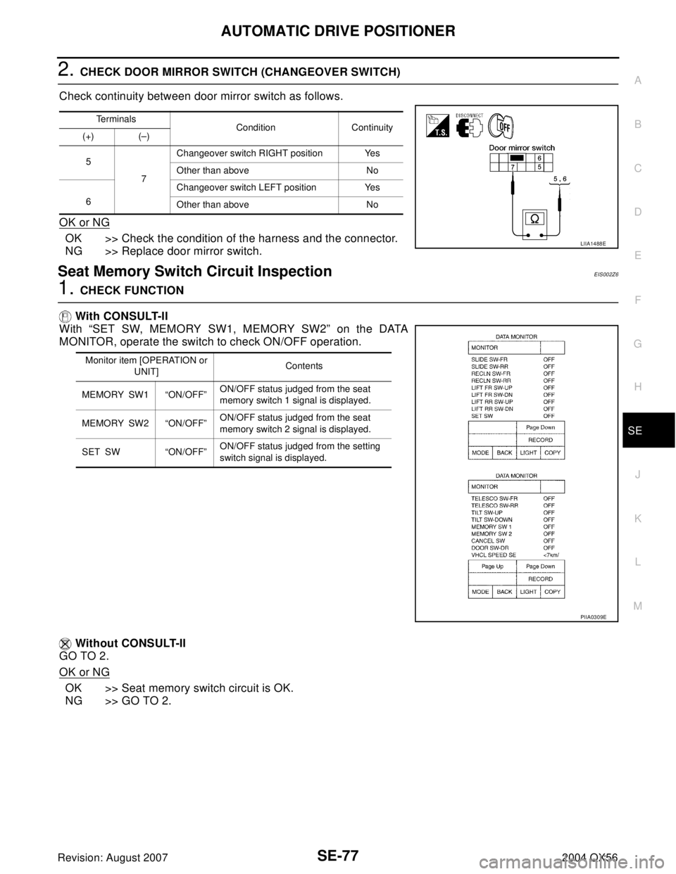
2. CHECK DOOR MIRROR SWITCH (CHANGEOVER SWITCH)
Check continuity between door mirror switch as follows.
OK or NG
OK >> Check the condition of the harness and the connector.
NG >> Replace door mirror switch.
Seat Memory Switch Circuit InspectionEIS002Z6
1. CHECK FUNCTION
With CONSULT-II
With “SET SW, MEMORY SW1, MEMORY SW2” on the DATA
MONITOR, operate the switch to check ON/OFF operation.
Without CONSULT-II
GO TO 2.
OK or NG
OK >> Seat memory switch circuit is OK.
NG >> GO TO 2.
Te r m i n a l s
Condition Continuity
(+) (–)
5
7Changeover switch RIGHT position Yes
Other than above No
6Changeover switch LEFT position Yes
Other than above No
LIIA1488E
Monitor item [OPERATION or
UNIT]Contents
MEMORY SW1 “ON/OFF”ON/OFF status judged from the seat
memory switch 1 signal is displayed.
MEMORY SW2 “ON/OFF”ON/OFF status judged from the seat
memory switch 2 signal is displayed.
SET SW “ON/OFF”ON/OFF status judged from the setting
switch signal is displayed.
PIIA0309E
Page 3031 of 3371
SE-82
AUTOMATIC DRIVE POSITIONER
Revision: August 20072004 QX56
3. CHECK DETENTION SWITCH
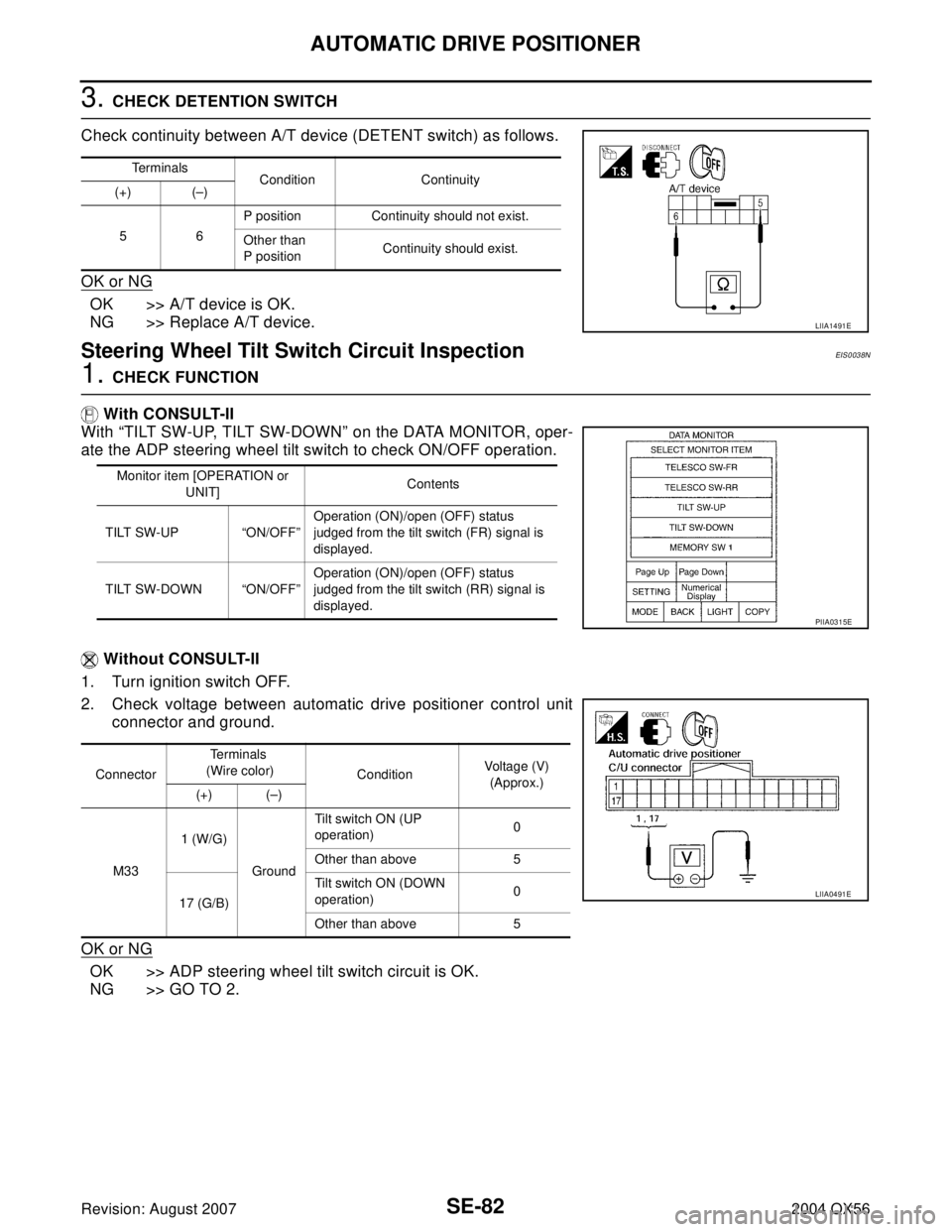
Check continuity between A/T device (DETENT switch) as follows.
OK or NG
OK >> A/T device is OK.
NG >> Replace A/T device.
Steering Wheel Tilt Switch Circuit InspectionEIS0038N
1. CHECK FUNCTION
With CONSULT-II
With “TILT SW-UP, TILT SW-DOWN” on the DATA MONITOR, oper-
ate the ADP steering wheel tilt switch to check ON/OFF operation.
Without CONSULT-II
1. Turn ignition switch OFF.
2. Check voltage between automatic drive positioner control unit
connector and ground.
OK or NG
OK >> ADP steering wheel tilt switch circuit is OK.
NG >> GO TO 2.
Terminals
Condition Continuity
(+) (–)
56P position Continuity should not exist.
Other than
P positionContinuity should exist.
LIIA1491E
Monitor item [OPERATION or
UNIT]Contents
TILT SW-UP “ON/OFF”Operation (ON)/open (OFF) status
judged from the tilt switch (FR) signal is
displayed.
TILT SW-DOWN “ON/OFF”Operation (ON)/open (OFF) status
judged from the tilt switch (RR) signal is
displayed.
PIIA0315E
ConnectorTe r m i n a l s
(Wire color)
ConditionVoltage (V)
(Approx.)
(+) (–)
M331 (W/G)
GroundTilt switch ON (UP
operation)0
Other than above 5
17 (G/B)Tilt switch ON (DOWN
operation)0
Other than above 5
LIIA0491E
Page 3033 of 3371
SE-84
AUTOMATIC DRIVE POSITIONER
Revision: August 20072004 QX56
Front Door Switch LH Circuit InspectionEIS0 02 ZA
1. CHECK FUNCTION
With CONSULT-II
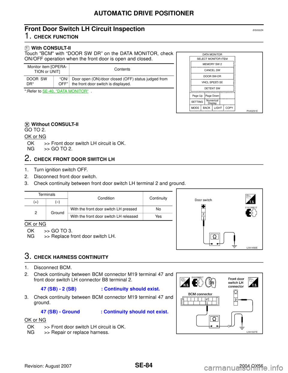
Touch "BCM" with “DOOR SW DR” on the DATA MONITOR, check
ON/OFF operation when the front door is open and closed.
*:Refer to SE-40, "DATA MONITOR" .
Without CONSULT-II
GO TO 2.
OK or NG
OK >> Front door switch LH circuit is OK.
NG >> GO TO 2.
2. CHECK FRONT DOOR SWITCH LH
1. Turn ignition switch OFF.
2. Disconnect front door switch.
3. Check continuity between front door switch LH terminal 2 and ground.
OK or NG
OK >> GO TO 3.
NG >> Replace front door switch LH.
3. CHECK HARNESS CONTINUITY
1. Disconnect BCM.
2. Check continuity between BCM connector M19 terminal 47 and
front door switch LH connector B8 terminal 2.
3. Check continuity between BCM connector M19 terminal 47 and
ground.
OK or NG
OK >> Front door switch LH circuit is OK.
NG >> Repair or replace harness.
Monitor item [OPERA-
TION or UNIT]Contents
DOOR SW
DR*“ON/
OFF”Door open (ON)/door closed (OFF) status judged from
the front door switch is displayed.
PIIA0291E
Terminals
Condition Continuity
(+) (–)
2GroundWith the front door switch LH pressed No
With the front door switch LH released Yes
LIIA1493E
47 (SB) - 2 (SB) : Continuity should exist.
47 (SB) - Ground : Continuity should not exist.
LIIA1027E
Page 3069 of 3371
SRS-8
TROUBLE DIAGNOSIS
Revision: August 20072004 QX56
TROUBLE DIAGNOSISPFP:00004
Trouble Diagnosis IntroductionEHS000WA
CAUTION:
�Do not use electrical test equipment on any circuit related to the SRS unless instructed to do so in
this Service Manual. SRS wiring harnesses can be identified by yellow and/or orange harness con-
nectors.
�Do not attempt to repair, splice or modify SRS wiring harnesses. If a harness is damaged, replace
it with a new one.
�Keep ground connections clean.
DIAGNOSIS FUNCTION
The SRS self-diagnosis results can be read by using “AIR BAG” warning lamp and/or CONSULT-II.
The User mode is exclusively prepared for the customer (driver). This mode warns the driver of a system mal-
function through the operation of the “AIR BAG” warning lamp.
The Diagnosis mode allows the technician to locate and inspect the malfunctioning part.
The mode applications for the “AIR BAG” warning lamp and CONSULT-II are as follows:
HOW TO PERFORM TROUBLE DIAGNOSES FOR QUICK AND ACCURATE REPAIR
A good understanding of the malfunction conditions can make troubleshooting faster and more accurate.
In general, each customer feels differently about a malfunction. It is important to fully understand the symp-
toms or conditions for a customer complaint.
Information From Customer
WHAT - Vehicle model
WHEN - Date, Frequencies
WHERE - Road conditions
HOW - Operating conditions, Symptoms
Preliminary Check
Check that the following parts are in good order.
�Battery (Refer to SC-4, "How to Handle Battery" .)
�Fuse (Refer to SRS-12, "Wiring Diagram — SRS —" .)
�System component-to-harness connections
User mode Diagnosis mode Display type
“AIR BAG” warning lamp X X ON-OFF operation
CONSULT-II — X Monitoring
Page 3079 of 3371
SRS-18
TROUBLE DIAGNOSIS
Revision: August 20072004 QX56
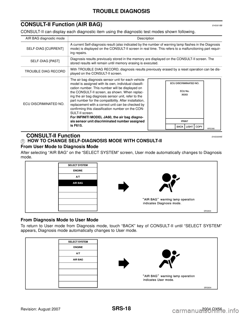
CONSULT-II Function (AIR BAG)EHS001BB
CONSULT-II can display each diagnostic item using the diagnostic test modes shown following.
CONSULT-II FunctionEHS000WE
HOW TO CHANGE SELF-DIAGNOSIS MODE WITH CONSULT-II
From User Mode to Diagnosis Mode
After selecting “AIR BAG” on the “SELECT SYSTEM” screen, User mode automatically changes to Diagnosis
mode.
From Diagnosis Mode to User Mode
To return to User mode from Diagnosis mode, touch “BACK” key of CONSULT-II until “SELECT SYSTEM”
appears, Diagnosis mode automatically changes to User mode.
AIR BAG diagnostic mode Description
SELF-DIAG [CURRENT]A current Self-diagnosis result (also indicated by the number of warning lamp flashes in the Diagnosis
mode) is displayed on the CONSULT-II screen in real time. This refers to a malfunctioning part requir-
ing repairs.
SELF-DIAG [PAST]Diagnosis results previously stored in the memory are displayed on the CONSULT-II screen. The
stored results will remain until memory erasing is executed.
TROUBLE DIAG RECORDWith TROUBLE DIAG RECORD, diagnosis results previously erased by a reset operation can be dis-
played on the CONSULT-II screen.
ECU DISCRIMINATED NO.The air bag diagnosis sensor unit for each vehicle
model is assigned with its own, individual classifi-
cation number. This number will be displayed on
the CONSULT-II screen, as shown. When replac-
ing the air bag diagnosis sensor unit, refer to the
part number for the compatibility. After installation,
replacement with a correct unit can be checked by
confirming this classification number on the CON-
SULT-II screen.
For INFINITI MODEL JA60, the air bag diagno-
sis sensor unit discriminated number assigned
is F615.
ARS3 66
SRS8 03
SRS8 04
Page 3080 of 3371
![INFINITI QX56 2004 Factory Service Manual TROUBLE DIAGNOSIS
SRS-19
C
D
E
F
G
I
J
K
L
MA
B
SRS
Revision: August 20072004 QX56
HOW TO ERASE SELF-DIAGNOSIS RESULTS
�“SELF-DIAG [CURRENT]”
A current self-diagnosis result is displayed on the C INFINITI QX56 2004 Factory Service Manual TROUBLE DIAGNOSIS
SRS-19
C
D
E
F
G
I
J
K
L
MA
B
SRS
Revision: August 20072004 QX56
HOW TO ERASE SELF-DIAGNOSIS RESULTS
�“SELF-DIAG [CURRENT]”
A current self-diagnosis result is displayed on the C](/manual-img/42/57034/w960_57034-3079.png)
TROUBLE DIAGNOSIS
SRS-19
C
D
E
F
G
I
J
K
L
MA
B
SRS
Revision: August 20072004 QX56
HOW TO ERASE SELF-DIAGNOSIS RESULTS
�“SELF-DIAG [CURRENT]”
A current self-diagnosis result is displayed on the CONSULT-II
screen in real time.
After the malfunction is repaired completely, no malfunction is
detected on “SELF-DIAG [CURRENT]”.
�“SELF-DIAG [PAST]”
Return to the “SELF-DIAG [CURRENT]” CONSULT-II screen by
touching “BACK” key of CONSULT-II and select “SELF-DIAG
[PAST]” in SELECT DIAG MODE. Touch “ERASE” in “SELF-
DIAG [PAST]” mode.
NOTE:
If the memory of the malfunction in “SELF-DIAG [PAST]” is
not erased, the User mode will continue to show the system
malfunction by the operation of the warning lamp even if
the malfunction is repaired completely.
�“TROUBLE DIAG RECORD”
The memory of “TROUBLE DIAG RECORD” cannot be erased.
Self-Diagnosis Function (Without CONSULT-II)EHS000WF
�The reading of these results is accomplished using one of two modes — “User mode” and “Diagnosis
mode”.
�After a malfunction is repaired, turn the ignition switch OFF for at least one second, then back ON. Diag-
nosis mode returns to the User mode. At that time, the self-diagnostic result is cleared.
HOW TO CHANGE SELF-DIAGNOSIS MODE
SRS7 01
SRS7 02
SHIA0183E
Page 3084 of 3371
![INFINITI QX56 2004 Factory Service Manual TROUBLE DIAGNOSIS
SRS-23
C
D
E
F
G
I
J
K
L
MA
B
SRS
Revision: August 20072004 QX56
7. Diagnostic code is displayed on "SELF-DIAG [CURRENT]".
If no malfunction is detected on "SELF-DIAG [CURRENT]" even INFINITI QX56 2004 Factory Service Manual TROUBLE DIAGNOSIS
SRS-23
C
D
E
F
G
I
J
K
L
MA
B
SRS
Revision: August 20072004 QX56
7. Diagnostic code is displayed on "SELF-DIAG [CURRENT]".
If no malfunction is detected on "SELF-DIAG [CURRENT]" even](/manual-img/42/57034/w960_57034-3083.png)
TROUBLE DIAGNOSIS
SRS-23
C
D
E
F
G
I
J
K
L
MA
B
SRS
Revision: August 20072004 QX56
7. Diagnostic code is displayed on "SELF-DIAG [CURRENT]".
If no malfunction is detected on "SELF-DIAG [CURRENT]" even
though malfunction is detected in "SRS Operation Check", refer to
SRS-30, "
DIAGNOSTIC PROCEDURE 4 (CONTINUED FROM
DIAGNOSTIC PROCEDURE 2)" , to diagnose the following cases:
�Self-diagnostic result "SELF-DIAG [PAST]" (previously stored in
the memory) might not be erased after repair.
�The SRS system malfunctions intermittently.
CONSULT-II Diagnostic Code Chart ("SELF-DIAG [CURRENT]")
WHIA0151E
SRS7 01
Diagnostic item ExplanationRepair order
Recheck SRS at each replacement
NO DTC IS DETECTEDWhen malfunction is
indicated by the “AIR
BAG” warning lamp in
User mode.
�Low battery voltage (Less than
9V)�Go to SRS-28, "DIAGNOSTIC PRO-
CEDURE 3" .
�Self-diagnostic result “SELF-DIAG
[PAST]” (previously stored in the
memory) might not be erased
after repair.
�Intermittent malfunction has been
detected in the past.
�Go to SRS-30, "DIAGNOSTIC PRO-
CEDURE 4 (CONTINUED FROM
DIAGNOSTIC PROCEDURE 2)" .
�Go to SRS-30, "DIAGNOSTIC PRO-
CEDURE 5" .
�No malfunction is detected. —
DRIVER AIRBAG MODULE
[OPEN]
[B1049] or [B1054]
�Driver air bag module circuit is open (including the spiral
cable).1. Visually check the wiring harness
connection.
2. Replace the harness if it has visible
damage.
3. Replace driver air bag module.
4. Replace the spiral cable.
5. Replace the air bag diagnosis sen-
sor unit.
6. Replace the related harness. DRIVER AIRBAG MODULE
[VB-SHORT]
[B1050] or [B1055]
�Driver air bag module circuit is shorted to some power sup-
ply circuit (including the spiral cable).
DRIVER AIRBAG MODULE
[GND-SHORT]
[B1051] or [B1056]
�Driver air bag module circuit is shorted to ground (including
the spiral cable).
DRIVER AIRBAG MODULE
[SHORT]
[B1052] or [B1057]
�Driver air bag module circuits are shorted to each other.
Page 3092 of 3371
TROUBLE DIAGNOSIS
SRS-31
C
D
E
F
G
I
J
K
L
MA
B
SRS
Revision: August 20072004 QX56
6. Touch “SELF-DIAG [PAST]”.
7. If diagnostic codes are displayed on “SELF-DIAG [PAST]”, go to
step 10.
If no malfunction is detected on “SELF-DIAG [PAST]”, touch
“BACK” and go back to “SELECT DIAG MODE”.
8. Touch “TROUBLE DIAG RECORD”.
NOTE:
With “TROUBLE DIAG RECORD”, diagnosis results previ-
ously erased by a reset operation can be displayed.
9. Diagnostic code is displayed on “TROUBLE DIAG RECORD”.
10. Touch “PRINT”.
11. Compare diagnostic codes to SRS-32, "
CONSULT-II Diagnostic
Code Chart ("SELF-DIAG [PAST]" or "TROUBLE DIAG
RECORD")" .
12. Touch “BACK” key of CONSULT-II until “SELECT SYSTEM”
appears.
13. Turn ignition switch OFF, then turn off and disconnect CON-
SULT-II, and both battery cables.
BCIA0031E
WHIA0152E
SRS7 02
BCIA0031E
WHIA0153E