Page 2892 of 3371
REAR SUSPENSION MEMBER
RSU-33
C
D
F
G
H
I
J
K
L
MA
B
RSU
Revision: August 20072004 QX56
INSTALLATION
Installation is in the reverse order of removal.
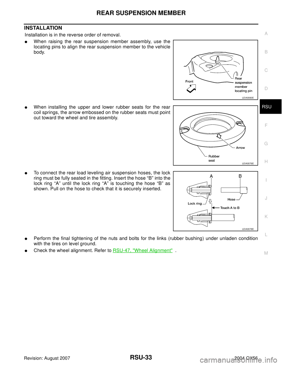
�When raising the rear suspension member assembly, use the
locating pins to align the rear suspension member to the vehicle
body.
�When installing the upper and lower rubber seats for the rear
coil springs, the arrow embossed on the rubber seats must point
out toward the wheel and tire assembly.
�To connect the rear load leveling air suspension hoses, the lock
ring must be fully seated in the fitting. Insert the hose “B” into the
lock ring “A” until the lock ring “A” is touching the hose “B” as
shown. Pull on the hose to check that it is securely inserted.
�Perform the final tightening of the nuts and bolts for the links (rubber bushing) under unladen condition
with the tires on level ground.
�Check the wheel alignment. Refer to RSU-47, "Wheel Alignment" .
LEIA0083E
LEIA0076E
LEIA0078E
Page 2893 of 3371

RSU-34
SHOCK ABSORBER
Revision: August 20072004 QX56
SHOCK ABSORBERPFP:56210
Removal and Installation EES0011J
REMOVAL
1. Remove the wheel and tire assembly using power tool. Refer to WT-6, "Rotation" .
2. Use CONSULT-II “EXHAUST SOLENOID” active test to release the air pressure from the rear load level-
ing air suspension system.
3. Remove the four clips and remove the rear fender protector, front.
4. Disconnect the rear load leveling air suspension hose from the
shock absorber.
�To disconnect the hose, push in on the lock ring using a suit-
able tool and pull the air hose out.
5. Remove the shock absorber upper and lower end bolts using
power tool.
6. Remove the shock absorber.
CAUTION:
Do not damage the rubber boot on the shock absorber.
INSTALLATION
Installation is in the reverse order of removal.
�Tighten the shock absorber bolts to specification. Refer to RSU-25, "Components" .
INSPECTION AFTER INSTALLATION
�Check the shock absorber for any air leaks or damage to the rubber boot.
�Check the shock absorber for smooth operation through a full stroke, both compression and extension.
�Check piston rod for cracks, deformation or other damage and replace if necessary.
LEIA0081E
LEIA0082E
Page 2901 of 3371

RSU-42
REAR LOAD LEVELING AIR SUSPENSION COMPRESSOR ASSEMBLY
Revision: August 20072004 QX56
REAR LOAD LEVELING AIR SUSPENSION COMPRESSOR ASSEMBLYPFP:53400
Removal and InstallationEES0011T
Rear Load Leveling Air Suspension System
REMOVAL
1. Use CONSULT-II "EXHAUST SOLENOID" active test to release the air pressure from the rear load level-
ing air suspension system.
2. Disconnect the electrical connectors for the rear load leveling air suspension compressor assembly.
3. Unclip the rubber cover to access the rear load leveling air suspension compressor assembly.
4. Disconnect the rear load leveling air suspension hoses at the
rear load leveling air suspension compressor assembly.
�To disconnect the hoses, push in on the lock ring using a suit-
able tool and pull the hose out.
LEIA0072E
1. Rear load leveling air suspension
hose, RH2. Shock absorber, RH 3. Height sensor
4. Rear load leveling air suspension
hose, LH5. Shock absorber, LH 6. Rear load leveling air suspension
compressor assembly
LEIA0074E
Page 2902 of 3371
REAR LOAD LEVELING AIR SUSPENSION COMPRESSOR ASSEMBLY
RSU-43
C
D
F
G
H
I
J
K
L
MA
B
RSU
Revision: August 20072004 QX56
5. Remove the four bolts that mount the rear load leveling air sus-
pension compressor assembly to the underbody.
INSTALLATION
Installation is in the reverse order of removal.
�To connect the rear load leveling air suspension hoses, the lock
ring must be fully seated in the fitting. Insert the hose “B” into the
lock ring “A” until the lock ring “A” is touching the hose “B” as
shown. Pull on the hose to check that it is securely inserted.
LEIA0090E
LEIA0078E
Page 2911 of 3371

SB-4
SEAT BELTS
Revision: August 20072004 QX56
REMOVAL OF SEAT BELT RETRACTOR
CAUTION:
�Before servicing SRS, turn the ignition switch off, disconnect both battery cables and wait at least
3 minutes.
1. Remove the center pillar upper/lower finishers. Refer to EI-34, "
BODY SIDE TRIM" .
2. Remove the seat belt retractor anchor bolts and seat belt retractor and belt assembly.
�On RH side, disconnect the seat belt tension sensor.
3. Disconnect the seat belt pre-tensioner electrical connector.
CAUTION:
�For installing/removing seat belt pre-tensioner connector,
insert a thin screwdriver wrapped in tape into the notch, lift
the lock and remove the connector.
�Install the connector with the lock raised, and push the lock
into the connector.
INSTALLATION OF SEAT BELT RETRACTOR
Installation is in the reverse order of removal.
�Install the seat belt retractor and belt assembly upper bolt first.
�Ensure that seat belt height adjuster is locked in the lowest position during installation.
WHIA0237E
PHIA0341E
Page 2914 of 3371

SEAT BELTS
SB-7
C
D
E
F
G
I
J
K
L
MA
B
SB
Revision: August 20072004 QX56
4. Remove the seat belt guide bolt.
5. Remove seat belt retractor anchor bolt and the seat belt retractor and belt assembly.
6. Remove the seat belt height adjustor assembly.
INSTALLATION
Installation is in the reverse order of removal.
�Ensure that seat belt height adjuster is locked in the lowest position during installation.
REMOVAL OF SEAT BELT BUCKLE
1. Remove the rear bucket seat. Refer to SE-103, "Removal and
Installation" .
2. Remove the screw and seat cushion finisher. Refer to SE-103,
"Removal and Installation" .
3. Remove the anchor bolt and buckle.
4. Remove the rear bench seat. Refer to SE-103, "
Removal and Installation" .
5. Remove the seat cushion finisher.
6. Remove the anchor bolt and buckle.
INSTALLATION OF SEAT BELT BUCKLE
Installation is in the reverse order of removal.
REMOVAL OF SEAT BELT RETRACTOR - BENCH SEAT
1. Remove seat belt anchor.
2. Remove seat belt bezel.
3. Remove seat back upholstery and foam. Refer to SE-103, "
Removal and Installation" .
4. Remove seat belt retractor cover.
5. Remove bolt and remove seat belt retractor and belt assembly.
INSTALLATION OF SEAT BELT RETRACTOR - BENCH SEAT
Installation is in the reverse order of removal.
WHIA0229E
Page 2916 of 3371
SEAT BELTS
SB-9
C
D
E
F
G
I
J
K
L
MA
B
SB
Revision: August 20072004 QX56
5. Remove the seat belt retractor anchor nut, RH side, and seat belt retractor and belt assembly.
6. Remove seat belt buckle anchor bolt from seat belt anchor base and remove seat belt buckles.
INSTALLATION
Installation is in the reverse order of removal.
�Ensure that seat belt height adjuster is locked in the lowest position during installation.
�Seat belt anchor base should be flat to the floor during installation and not on the anti-rotation bead.
Third Row Center EHS000VU
REMOVAL AND INSTALLATION
REMOVAL
1. Remove the rear roof finisher. Refer to EI-37, "HEADLINING" .
2. Lower the rear portion of the headliner.
3. Remove the seat belt retractor anchor bolts and seat belt retractor and belt assembly.
INSTALLATION
Installation is in the reverse order of removal.
WHIA0230E
Page 2918 of 3371
 and Automatic Locking Retractors (ALR)
NOTE:
All seat")
SEAT BELTS
SB-11
C
D
E
F
G
I
J
K
L
MA
B
SB
Revision: August 20072004 QX56
SEAT BELT RETRACTOR ON-VEHICLE CHECK
Emergency Locking Retractors (ELR) and Automatic Locking Retractors (ALR)
NOTE:
All seat belt retractors are of the Emergency Locking Retractors (ELR) type. In an emergency (sudden stop)
the retractor will lock and prevent the belt from extending any further. All 3-point type seat belt retractors
except the driver's seat belt also have an Automatic Locking Retractors (ALR) mode. The ALR mode (also
called child restraint mode) is used when installing child seats. The ALR mode is activated when the seat belt
is fully extended. When the belt is then retracted partially, the ALR mode automatically locks the seat belt in a
specific position so the belt cannot be extended any further. To cancel the ALR mode, allow the seat belt to
fully wind back into the retractor.
Check the seat belt retractors using the following test(s) to determine if a seat belt retractor and belt assembly
is operating properly.
ELR Function Stationary Check
Grasp the shoulder belt and pull forward quickly. The retractor should lock and prevent the belt from extending
further.
ALR Function Stationary Check
1. Pull out entire length of seat belt from retractor until a click is heard.
2. Retract the belt partially. A clicking noise should be heard as the belt retracts indicating that the retractor is
in the Automatic Locking Retractor (ALR) mode.
3. Grasp the seat belt and try to pull out the retractor. The belt must lock and not extend any further. If neces-
sary replace the seat belt retractor and belt assembly.
4. Allow the entire length of the belt to retract to cancel the automatic locking mode.
ELR Function Moving Check
WA RN ING:
Perform the following test in a safe, open area clear of other vehicles and obstructions (for example, a
large, empty parking lot). Road surface must be paved and dry. DO NOT perform the following test on
wet or gravel roads or on public streets and highways. This could result in an accident and serious
personal injury. The driver and passenger must be prepared to brace themselves in the event the
retractor does not lock.
1. Fasten drivers seat belt. Buckle a passenger into the seat for the belt that is to be tested.
2. Proceed to the designated safe area.
3. Drive the vehicle at approximately 16 km/h (10 MPH). Notify any passengers of a pending sudden stop.
The driver and passenger must be prepared to brace themselves in the event the retractor does not lock.
Apply brakes firmly and make a very hard stop.
During stop, seat belts should lock and not be extended. If the seat belt retractor and belt assembly does not
lock, perform the retractor off-vehicle check.
SEAT BELT RETRACTOR OFF-VEHICLE CHECK
1. Remove the seat belt retractor and belt assembly.
2. Slowly pull out belt while tilting the retractor assembly forward from the mounted position without twisting
the retractor assembly as shown in the illustration.