Page 2720 of 3371
EKS007NZ
Use the chart below to find out what each wiring diagram code stands for.
Refer to the")
HARNESS
PG-61
C
D
E
F
G
H
I
J
L
MA
B
PG
Revision: August 20072004 QX56
Wiring Diagram Codes (Cell Codes)EKS007NZ
Use the chart below to find out what each wiring diagram code stands for.
Refer to the wiring diagram code in the alphabetical index to find the location (page number) of each wiring
diagram.
Code Section Wiring Diagram Name
A/C,A ATC Auto Air Conditioner
A/SUSP RSU Rear Air Suspension
AF1B1 EC Air Fuel Ratio Sensor 1 (Bank 1)
AF1B2 EC Air Fuel Ratio Sensor 1 (Bank 2)
AF1HB1 EC Air Fuel Ratio Sensor 1 (Bank 1)
AF1HB2 EC Air Fuel Ratio Sensor 1 (Bank 2)
APPS1 EC Accelerator Pedal Position Sensor
APPS2 EC Accelerator Pedal Position Sensor
APPS3 EC Accelerator Pedal Position Sensor
ASC/BS EC ASCD Brake Switch
ASC/SW EC ASCD Steering Switch
ASCBOF EC ASCD Brake Switch
ASCIND EC ASCD Indicator
A/T AT A/T Assembly
AT/IND DI A/T Indicator Lamp
AUDIO AV Audio
AUTO/DP SE Automatic Drive Positioner
AUTO/L LT Auto Light Control
B/CLOS BL Back Door Auto Closure System
BACK/L LT Back-up Lamp
BRK/SW EC Brake Switch
CAN EC CAN Communication Line
CAN LAN CAN System
CHARGE SC Charging System
CHIME DI Warning Chime
CLOCK DI Clock
COMBSW LT Combination Switch
COMM AV Audio Visual Communication System
COMPAS DI Compass and Thermometer
COOL/F EC Cooling Fan Control
D/LOCK BL Power Door Lock
DEF GW Rear Window Defogger
DTRL LT Headlamp - With Daytime Light System
DVD AV DVD Entertainment System
ECM/PW EC ECM Power Supply for Back-Up
ECTS EC Engine Coolant Temperature Sensor
ETC1 EC Electric Throttle Control Function
ETC2 EC Throttle Control Motor Relay
ETC3 EC Throttle Control Motor
F/FOG LT Front Fog Lamp
F/PUMP EC Fuel Pump
FTTS EC Fuel Tank Temperature Sensor
FUELB1 EC Fuel Injection System Bank 1
FUELB2 EC Fuel Injection System Bank 2
H/AIM LT Headlamp Aiming Control
H/LAMP LT Headlamp
HORN WW Horn
Page 2721 of 3371

PG-62
HARNESS
Revision: August 20072004 QX56
HSEAT SE Heated Seat
IATS EC Intake Air Temperature Sensor
ICC ACS Intelligent Cruise Control
ICCBOF EC ICC Brake Switch
ICC/BS EC ICC Steering Switch
ICC/SW EC ICC Brake Switch
I/MIRR GW Inside Mirror (Auto Anti-Dazzling Mirror)
IGNSYS EC Ignition System
ILL LT Illumination
INJECT EC Injector
INT/L LT Room/Map, Vanity, Cargo, Personal, Foot, Step, and Puddle Lamps
KEYLES BL Remote Keyless Entry System
KS EC Knock Sensor
MAFS EC Mass Air Flow Sensor
MAIN EC Main Power Supply and Ground Circuit
METER DI Speedometer, Tachometer, Temp. and Fuel Gauges
MIL/DL EC Malfunction Indicator Lamp
MIRROR GW Door Mirror
NATS BL Nissan Anti-Theft System
NAVI AV Navigation System
O2H2B1 EC Rear Heated Oxygen Sensor 2 Heater Bank 1
O2H2B2 EC Rear Heated Oxygen Sensor 2 Heater Bank 2
O2S2B1 EC Heated Oxygen Sensor 2 Bank 1
O2S2B2 EC Heated Oxygen Sensor 2 Bank 2
P/SCKT WW Power Socket
PGC/V EC EVAP Canister Purge Volume Control Solenoid Valve
PHASE EC Camshaft Position Sensor (PHASE) (Bank 1)
PNP/SW EC Park/Neutral Position Switch
POS EC Crankshaft Position Sensor (POS)
POWER PG Power Supply Routing
PRE/SE EC EVAP Control System Pressure Sensor
PS/SEN EC Power Steering Pressure Sensor
R/VIEW DI Rear View Monitor
RP/SEN EC Refrigerant Pressure Sensor
SEAT SE Power Seat (Without Memory)
SEN/PW EC Sensor Power Supply
SHIFT AT A/T Shift Lock System
SONAR DI Rear Sonar System
SROOF RF Sunroof
SRS SRS Supplemental Restraint System
START SC Starting System
STOP/L LT Stop Lamp
T/TOW LT Trailer Tow
T/WARN WT Low Tire Pressure Warning System
TAIL/L LT Parking, License and Tail Lamps
T/F TF Transfer Case
TPS1 EC Throttle Position Sensor
TPS2 EC Throttle Position Sensor
TPS3 EC Throttle Position Sensor
TRNSCV BL HOMELINK® Universal Transceiver
TURN LT Turn Signal and Hazard Warning Lamps
VDC BRC Vehicle Dynamic Control System
Page 2726 of 3371

ELECTRICAL UNITS LOCATION
PG-67
C
D
E
F
G
H
I
J
L
MA
B
PG
Revision: August 20072004 QX56
Fuse EKS007O1
�If fuse is blown, be sure to eliminate cause of incident before
installing new fuse.
�Use fuse of specified rating. Never use fuse of more than speci-
fied rating.
�Do not partially install fuse; always insert it into fuse holder prop-
erly.
�Remove fuse for “ELECTRICAL PARTS (BAT)” if vehicle is not
used for a long period of time.
Fusible Link EKS007O2
A melted fusible link can be detected either by visual inspection or by feeling with finger tip. If its condition is
questionable, use circuit tester or test lamp.
CAUTION:
�If fusible link should melt, it is possible that critical circuit (power supply or large current carrying
circuit) is shorted. In such a case, carefully check and eliminate cause of incident.
�Never wrap outside of fusible link with vinyl tape.
�Never let fusible link touch any other wiring harness, vinyl or rubber parts.
Circuit Breaker (Built Into BCM)EKS007O3
For example, when current is 30A, the circuit is broken within 8 to 20
seconds.
A circuit breaker is used for the following systems:
�Power windows
�Power door locks
�Remote keyless entry system
�Power sunroof
�Rear window wiper
CEL083
SBF 2 84 E
Page 2727 of 3371
PG-68
HARNESS CONNECTOR
Revision: August 20072004 QX56
HARNESS CONNECTORPFP:B4341
DescriptionEKS007O4
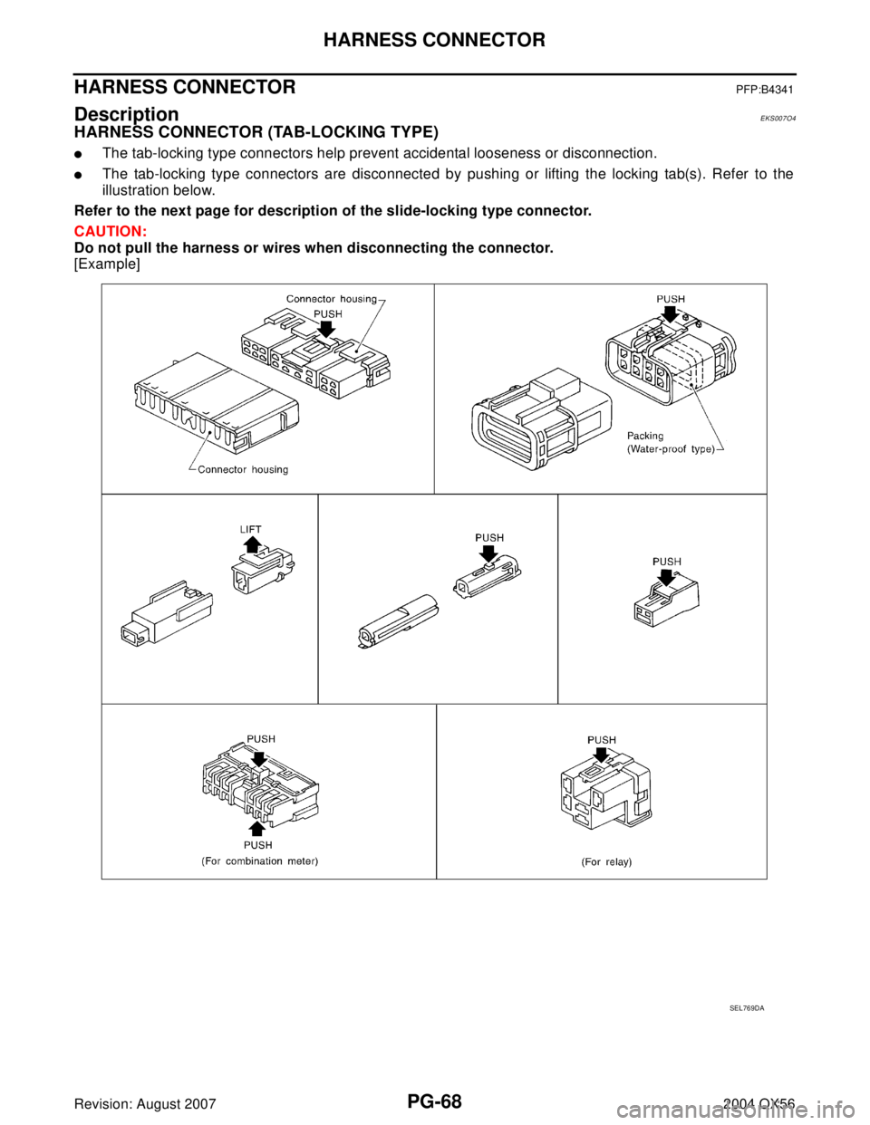
HARNESS CONNECTOR (TAB-LOCKING TYPE)
�The tab-locking type connectors help prevent accidental looseness or disconnection.
�The tab-locking type connectors are disconnected by pushing or lifting the locking tab(s). Refer to the
illustration below.
Refer to the next page for description of the slide-locking type connector.
CAUTION:
Do not pull the harness or wires when disconnecting the connector.
[Example]
SEL769DA
Page 2728 of 3371
HARNESS CONNECTOR
PG-69
C
D
E
F
G
H
I
J
L
MA
B
PG
Revision: August 20072004 QX56
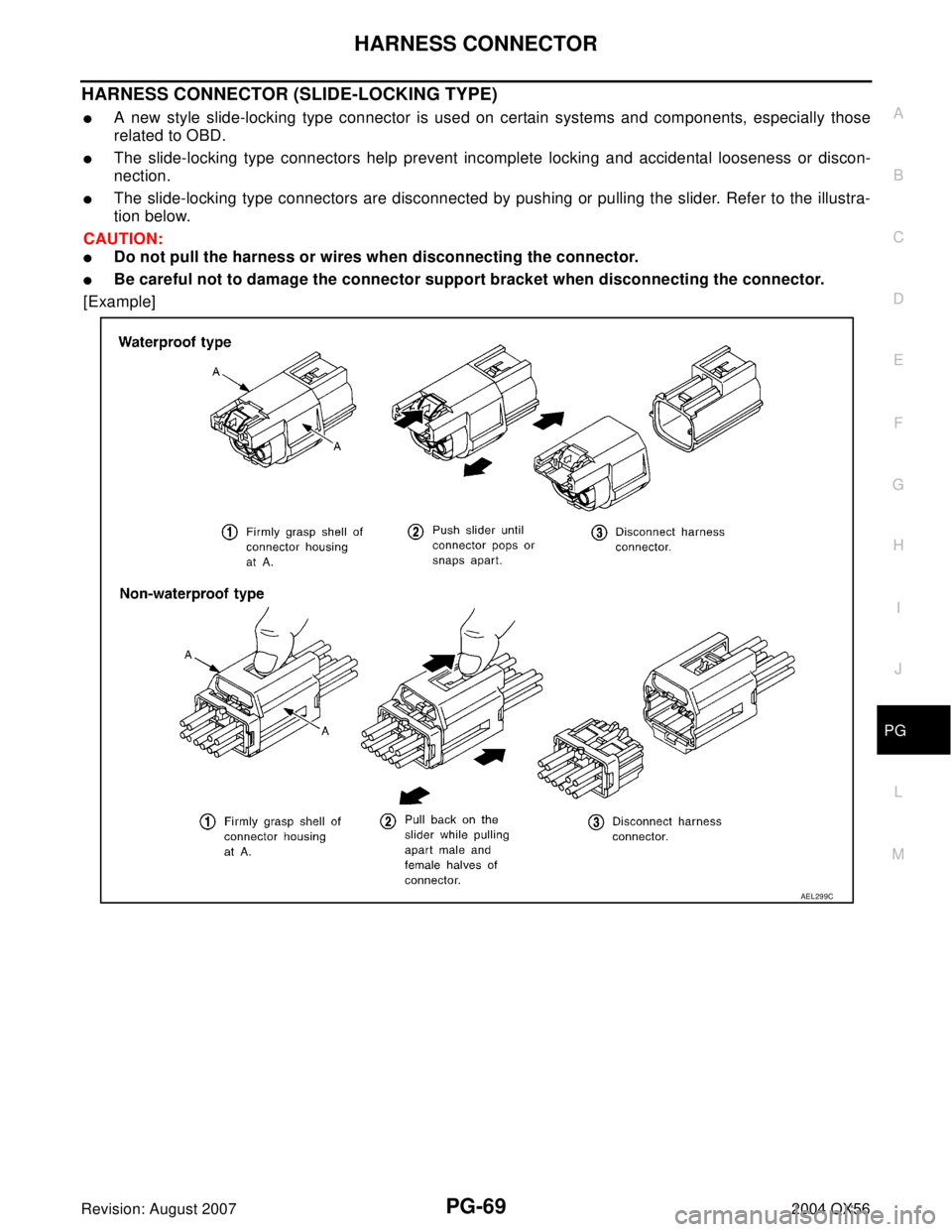
HARNESS CONNECTOR (SLIDE-LOCKING TYPE)
�A new style slide-locking type connector is used on certain systems and components, especially those
related to OBD.
�The slide-locking type connectors help prevent incomplete locking and accidental looseness or discon-
nection.
�The slide-locking type connectors are disconnected by pushing or pulling the slider. Refer to the illustra-
tion below.
CAUTION:
�Do not pull the harness or wires when disconnecting the connector.
�Be careful not to damage the connector support bracket when disconnecting the connector.
[Example]
AEL299C
Page 2729 of 3371
PG-70
HARNESS CONNECTOR
Revision: August 20072004 QX56
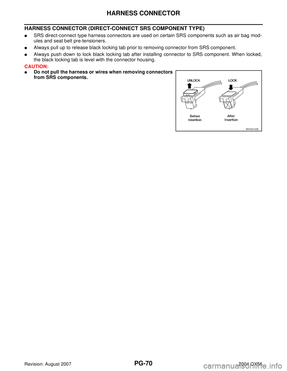
HARNESS CONNECTOR (DIRECT-CONNECT SRS COMPONENT TYPE)
�SRS direct-connect type harness connectors are used on certain SRS components such as air bag mod-
ules and seat belt pre-tensioners.
�Always pull up to release black locking tab prior to removing connector from SRS component.
�Always push down to lock black locking tab after installing connector to SRS component. When locked,
the black locking tab is level with the connector housing.
CAUTION:
�Do not pull the harness or wires when removing connectors
from SRS components.
WHIA0103E
Page 2735 of 3371
PG-76
FUSE BLOCK-JUNCTION BOX(J/B)
Revision: August 20072004 QX56
FUSE BLOCK-JUNCTION BOX(J/B)PFP:24350
Terminal ArrangementEKS007O8
WKIA2016E
Page 2756 of 3371
 TROUBLESHOOTING
PS-5
C
D
E
F
H
I
J
K
L
MA
B
PS
Revision: August 20072004 QX56
NOISE, VIBRATION, AND HARSHNESS (NVH) TROUBLESHOOTINGPFP:00003
NVH Troubleshooting C")
NOISE, VIBRATION, AND HARSHNESS (NVH) TROUBLESHOOTING
PS-5
C
D
E
F
H
I
J
K
L
MA
B
PS
Revision: August 20072004 QX56
NOISE, VIBRATION, AND HARSHNESS (NVH) TROUBLESHOOTINGPFP:00003
NVH Troubleshooting ChartEGS000MM
Use chart below to help you find the cause of the symptom. If necessary, repair or replace these parts.
×: ApplicableReference page
PS-6PS-6PS-20PS-20PS-20PS-6PS-7PS-7EM-12PS-7PS-13PS-15PS-11PS-10PS-15
PR-3, "
NVH Troubleshooting Chart
"
FFD-7, "
NVH Troubleshooting Chart
"
FA X-4, "
NVH Troubleshooting Chart
"
FSU-4, "
NVH Troubleshooting Chart
"
WT-3, "
NVH Troubleshooting Chart
"
WT-3, "
NVH Troubleshooting Chart
"
FA X-4, "
NVH Troubleshooting Chart
"
BR-5, "
NVH Troubleshooting Chart
"
Possible cause and sus-
pected parts
Fluid level
Air in hydraulic system
Outer socket ball joint swinging force
Outer socket ball joint rotating torque
Outer socket ball joint end play
Steering fluid leakage
Steering wheel play
Steering gear rack sliding force
Drive belt looseness
Improper steering wheel
Improper installation or looseness of tilt lock lever
Mounting rubber deterioration
Steering column deformation or damage
Improper installation or looseness of steering column
Steering linkage looseness
PROPELLER SHAFT
FRONT FINAL DRIVE
WHEEL HUB
FRONT SUSPENSION
TIRES
ROAD WHEEL
DRIVE SHAFT
BRAKES
SymptomNoise× × ××××× × × ××××××× ×
Shake××× × ××××× ×
Vibration××××× × ××× ×
Shimmy××× × ×××× ×
Shudder× × ×××× ×

Revision: August 20072004 QX56
FUSE BLOCK-JUNCTION BOX(J/B)PFP:24350
Terminal ArrangementEKS007O8
WKIA2016E")