Page 3192 of 3371
TRANSFER FLUID TEMPERATURE SENSOR
TF-67
C
E
F
G
H
I
J
K
L
MA
B
TF
Revision: August 20072004 QX56
3. CHECK INPUT SIGNAL
With CONSULT-II
1. Start engine.
2. Select “ECU INPUT SIGNALS” in Data Monitor.
3. Read out the value of “FLUID TEMP SE”.
OK or NG
OK >> GO TO 5.
NG >> Check the following.
�Continuity between transfer control unit and transfer terminal cord assembly harness connectorVo l ta g e
20°C (68°F) : Approx. 1.1V
80°C (176°F) : Approx. 0.3V
SMT784D
SMT974D
Page 3202 of 3371

SHIFT ACTUATOR
TF-77
C
E
F
G
H
I
J
K
L
MA
B
TF
Revision: August 20072004 QX56
SHIFT ACTUATORPFP:00000
Diagnostic ProcedureEDS0018B
1. SHIFT ACTUATOR
Refer to TF-97, "
ACTUATOR AND ACTUATOR POSITION SWITCH" .
OK or NG
OK >> GO TO 3.
NG >> GO TO 2.
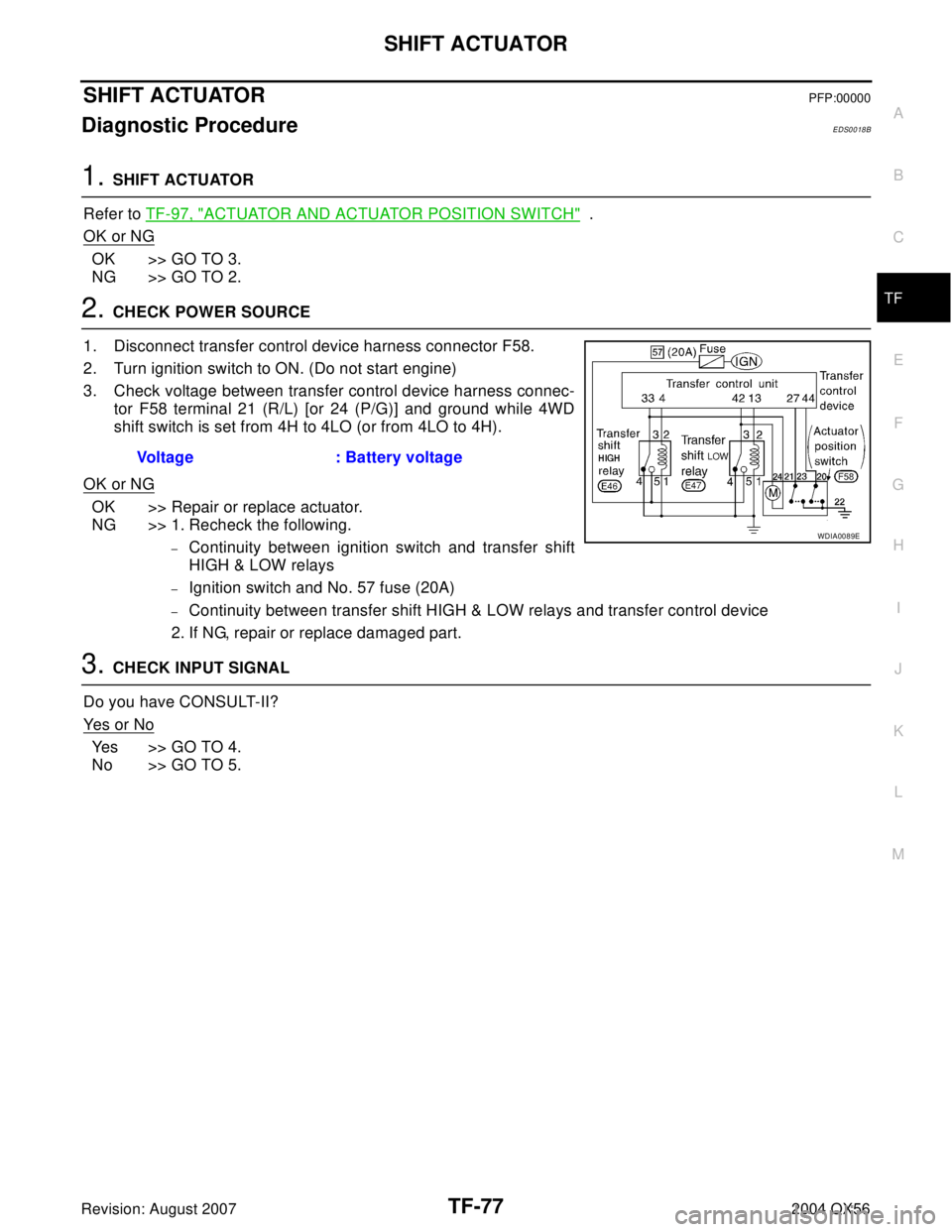
2. CHECK POWER SOURCE
1. Disconnect transfer control device harness connector F58.
2. Turn ignition switch to ON. (Do not start engine)
3. Check voltage between transfer control device harness connec-
tor F58 terminal 21 (R/L) [or 24 (P/G)] and ground while 4WD
shift switch is set from 4H to 4LO (or from 4LO to 4H).
OK or NG
OK >> Repair or replace actuator.
NG >> 1. Recheck the following.
–Continuity between ignition switch and transfer shift
HIGH & LOW relays
–Ignition switch and No. 57 fuse (20A)
–Continuity between transfer shift HIGH & LOW relays and transfer control device
2. If NG, repair or replace damaged part.
3. CHECK INPUT SIGNAL
Do you have CONSULT-II?
Ye s o r N o
Yes >> GO TO 4.
No >> GO TO 5.Voltage : Battery voltage
WDIA0089E
Page 3203 of 3371
TF-78
SHIFT ACTUATOR
Revision: August 20072004 QX56
4. CHECK INPUT SIGNAL
With CONSULT-II
1. Start engine (idling).
2. Select “SELF-DIAG RESULTS” in Select Diag Mode.
3. Read out self-diagnostic result.
OK or NG
OK >> GO TO 7.
NG >> GO TO 6.
5. CHECK INPUT SIGNAL
Without CONSULT-II
1. Start engine (idling).
2. Check voltage between transfer control unit harness connector
E143 terminal 33 (R/L) [or 42 (P/G)] and ground while 4WD shift
switch is set from 4H to 4LO (or from 4LO to 4H).
3. Result
OK or NG
OK >> GO TO 7.
NG >> GO TO 6.
SMT826D
SMT978D
Terminal ConditionVo l ta g e
(Approx.)
33While actuator is
operating for 4H to
4LOBattery voltage
Actuator does not
operate0V
42While actuator is
operating for 4LO to
4HBattery voltage
Actuator does not
operate0V
SMT828D
Page 3205 of 3371
TF-80
SHIFT ACTUATOR POSITION SWITCH
Revision: August 20072004 QX56
SHIFT ACTUATOR POSITION SWITCHPFP:00000
Diagnostic ProcedureEDS0018C
1. SHIFT ACTUATOR POSITION SWITCH
Refer to TF-97, "
ACTUATOR AND ACTUATOR POSITION SWITCH" .
OK or NG
OK >> GO TO 3.
NG >> GO TO 2.
2. CHECK POSITION SWITCH
Recheck continuity of shift actuator position switch.
Refer to TF-97, "
ACTUATOR AND ACTUATOR POSITION SWITCH" .
Continuity should exist.
OK or NG
OK >> GO TO 3.
NG >> Repair or replace position switch.
3. CHECK INPUT SIGNAL
Do you have CONSULT-II?
Ye s o r N o
Yes >> GO TO 4.
No >> GO TO 5.
4. CHECK INPUT SIGNAL
With CONSULT-II
1. Start engine (idling).
2. Select “SELF-DIAG RESULTS” in Select Diag Mode.
3. Read out self-diagnostic result.
OK or NG
OK >> GO TO 6.
NG >> Check the following.
�Continuity between transfer control unit and transfer
control device.
�Check ground circuit between transfer control device
and ground.
WDIA0078E
SMT978D
Page 3206 of 3371

SHIFT ACTUATOR POSITION SWITCH
TF-81
C
E
F
G
H
I
J
K
L
MA
B
TF
Revision: August 20072004 QX56
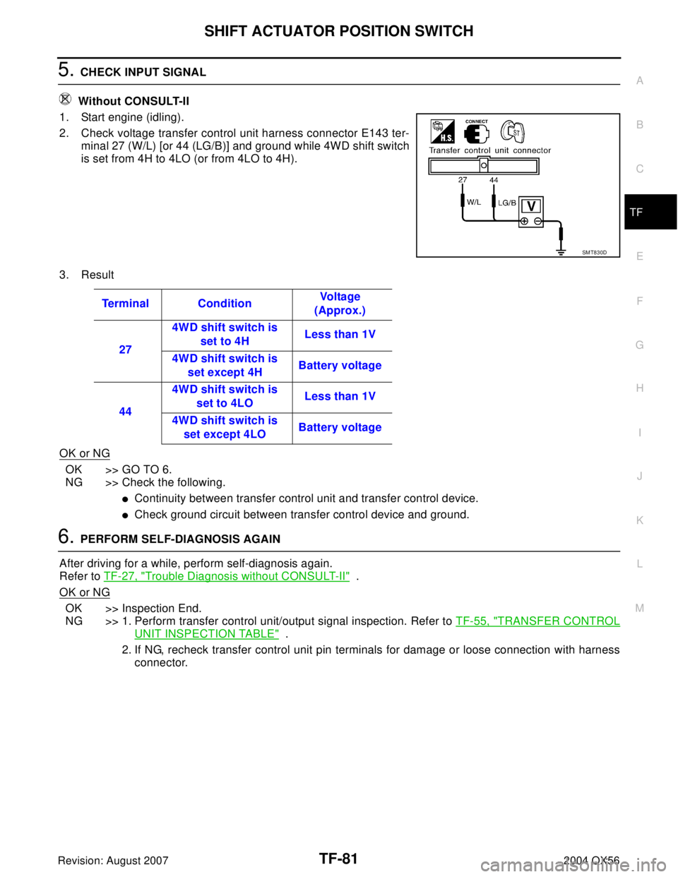
5. CHECK INPUT SIGNAL
Without CONSULT-II
1. Start engine (idling).
2. Check voltage transfer control unit harness connector E143 ter-
minal 27 (W/L) [or 44 (LG/B)] and ground while 4WD shift switch
is set from 4H to 4LO (or from 4LO to 4H).
3. Result
OK or NG
OK >> GO TO 6.
NG >> Check the following.
�Continuity between transfer control unit and transfer control device.
�Check ground circuit between transfer control device and ground.
6. PERFORM SELF-DIAGNOSIS AGAIN
After driving for a while, perform self-diagnosis again.
Refer to TF-27, "
Trouble Diagnosis without CONSULT-II" .
OK or NG
OK >> Inspection End.
NG >> 1. Perform transfer control unit/output signal inspection. Refer to TF-55, "
TRANSFER CONTROL
UNIT INSPECTION TABLE" .
2. If NG, recheck transfer control unit pin terminals for damage or loose connection with harness
connector.
SMT830D
Terminal ConditionVo l ta g e
(Approx.)
274WD shift switch is
set to 4HLess than 1V
4WD shift switch is
set except 4HBattery voltage
444WD shift switch is
set to 4LOLess than 1V
4WD shift switch is
set except 4LOBattery voltage
Page 3207 of 3371
TF-82
SHIFT ACTUATOR CIRCUIT
Revision: August 20072004 QX56
SHIFT ACTUATOR CIRCUITPFP:00000
Diagnostic ProcedureEDS0018D
1. SHIFT ACTUATOR CIRCUIT
Refer to TF-97, "
TRANSFER SHIFT RELAY (HIGH & LOW)" and TF-97, "ACTUATOR AND ACTUATOR
POSITION SWITCH" .
OK or NG
OK >> GO TO 2.
NG >> Repair or replace transfer shift relay and actuator and actuator position switch.
2. CHECK POWER SOURCE OF TRANSFER SHIFT (HI & LOW) RELAY
1. Disconnect transfer control device harness connector F58.
2. Turn ignition switch to ON (Do not start engine).
3. Check voltage between transfer shift HIGH relay E46 and LOW relay E47 terminal 5 (R) and ground.
OK or NG
OK >> GO TO 3.
NG >> Check the following.
�Continuity between ignition switch and transfer shift HIGH & LOW relays
�Ignition switch and No. 57 fuse (20A)
WDIA0089E
Voltage : Battery voltage
LDIA0080E
Page 3208 of 3371
SHIFT ACTUATOR CIRCUIT
TF-83
C
E
F
G
H
I
J
K
L
MA
B
TF
Revision: August 20072004 QX56
3. CHECK POWER SOURCE OF TRANSFER CONTROL DEVICE
1. Disconnect transfer control device harness connector F58.
2. Turn ignition switch to ON. (Do not start engine)
3. Turn 4WD shift switch from 4H to 4LO (or from 4LO to 4H).
4. Check voltage between transfer control device harness connec-
tor F58 terminal 21 (R/L) [or 24 (P/G)] and ground.
OK or NG
OK >> GO TO 4.
NG >> Check the following.
�Harness and connector from transfer shift HIGH and LOW relays to transfer control device har-
ness terminal
�Ground circuit between transfer control device and ground.
4. CHECK INPUT SIGNAL
Do you have CONSULT-II?
Ye s o r N o
Yes >> GO TO 5.
No >> GO TO 6.
5. CHECK INPUT SIGNAL
With CONSULT-II
1. Start engine (idling).
2. Select “SELF-DIAG RESULTS” in Select Diag Mode.
3. Read out self-diagnostic result.
OK or NG
OK >> GO TO 8.
NG >> GO TO 7.Voltage : Battery voltage
LDIA0081E
LDIA0082E
SMT978D
Page 3209 of 3371

TF-84
SHIFT ACTUATOR CIRCUIT
Revision: August 20072004 QX56
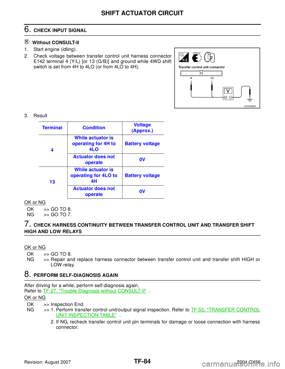
6. CHECK INPUT SIGNAL
Without CONSULT-II
1. Start engine (idling).
2. Check voltage between transfer control unit harness connector
E142 terminal 4 (Y/L) [or 13 (G/B)] and ground while 4WD shift
switch is set from 4H to 4LO (or from 4LO to 4H).
3. Result
OK or NG
OK >> GO TO 8.
NG >> GO TO 7.
7. CHECK HARNESS CONTINUITY BETWEEN TRANSFER CONTROL UNIT AND TRANSFER SHIFT
HIGH AND LOW RELAYS
OK or NG
OK >> GO TO 8.
NG >> Repair and replace harness connector between transfer control unit and transfer shift HIGH or
LOW relay.
8. PERFORM SELF-DIAGNOSIS AGAIN
After driving for a while, perform self-diagnosis again.
Refer to TF-27, "
Trouble Diagnosis without CONSULT-II" .
OK or NG
OK >> Inspection End.
NG >> 1. Perform transfer control unit/output signal inspection. Refer to TF-55, "
TRANSFER CONTROL
UNIT INSPECTION TABLE" .
2. If NG, recheck transfer control unit pin terminals for damage or loose connection with harness
connector.
LDIA0083E
Terminal ConditionVo l ta g e
(Approx.)
4While actuator is
operating for 4H to
4LOBattery voltage
Actuator does not
operate0V
13While actuator is
operating for 4LO to
4HBattery voltage
Actuator does not
operate0V