Page 2886 of 3371

REAR SUSPENSION ASSEMBLY
RSU-27
C
D
F
G
H
I
J
K
L
MA
B
RSU
Revision: August 20072004 QX56
Wheel Alignment InspectionEES0011H
Rear Wheel Alignment Adjusting Bolts
PRELIMINARY INSPECTION
WA RN ING:
Always adjust the alignment with the vehicle on a flat surface. Use CONSULT-II "EXHAUST SOLE-
NOID" active test to release the air pressure from the rear load leveling air suspension system.
NOTE:
If alignment is out of specification, inspect and replace any damaged or worn rear suspension parts before
making any adjustments.
1. Check and adjust the wheel alignment with the vehicle under unladen conditions. “Unladen conditions”
means that the fuel, coolant, and lubricant are full; and that the spare tire, jack, hand tools and mats are in
their designated positions.
2. Check the tires for incorrect air pressure and excessive wear.
3. Check the wheels for runout and damage. Refer to WT-4, "
Inspection" .
4. Check the wheel bearing axial end play.
5. Check the shock absorbers. Refer to RSU-26, "
SHOCK ABSORBER INSPECTION" .
6. Check each mounting point of the suspension components for any excessive looseness or damage.
7. Check each link, arm, and the rear suspension member for any damage.
8. Check the vehicle height. Refer to RSU-48, "
Wheelarch Height (Unladen*1 )" .
�Verify the vehicle height using Consult-II memory register 1103 and set to 0 ± 10 mm (0 ± 0.39 in) as
necessary.
GENERAL INFORMATION AND RECOMMENDATIONS
1. A Four-Wheel Thrust Alignment should be performed.
�This type of alignment is recommended for any NISSAN vehicle.
�The four-wheel “thrust” process helps ensure that the vehicle is properly aligned and the steering wheel
is centered.
�The alignment machine itself should be capable of accepting any NISSAN vehicle.
�The alignment machine should be checked to ensure that it is level.
2. Make sure the alignment machine is properly calibrated.
�Your alignment machine should be regularly calibrated in order to give correct information.
WEIA0102E
1. Rear lower link adjusting bolt, LH 2. Front lower link adjusting bolt, LH 3. Front lower link adjusting bolt, RH
4. Rear lower link adjusting bolt, RH
Axial end play : 0 mm (0 in)
Page 2887 of 3371

RSU-28
REAR SUSPENSION ASSEMBLY
Revision: August 20072004 QX56
�Check with the manufacturer of your specific alignment machine for their recommended Service/Cali-
bration Schedule.
THE ALIGNMENT PROCESS
IMPORTANT: Use only the alignment specifications listed in this Service Manual. Refer to RSU-47, "Wheel
Alignment" .
1. When displaying the alignment settings, many alignment machines use “indicators”: (Green/red, plus or
minus, Go/No Go). Do NOT use these indicators.
�The alignment specifications programmed into your alignment machine that operate these indicators
may not be correct.
�This may result in an ERROR.
2. Some newer alignment machines are equipped with an optional “Rolling Compensation” method to “com-
pensate” the sensors (alignment targets or head units). Do NOT use this “Rolling Compensation”
method.
�Use the “Jacking Compensation” method. After installing the alignment targets or head units, raise the
vehicle and rotate the wheels 1/2 turn both ways.
�See Instructions in the alignment machine you are using for more information.
CAMBER
1. Measure camber of both the right and left wheels with a suitable
alignment gauge and adjust as necessary to specification.
2. If outside of the specified value, adjust the camber using the
adjusting bolt in the front lower link.
CAUTION:
After adjusting the camber then check the toe-in.
NOTE:
Camber changes about 5' minutes with each graduation of the
adjusting bolt.
3. Tighten the adjusting bolt nuts to specification.
TOE-IN
1. Bounce the rear of the vehicle up and down two to three times to stabilize the vehicle height. Refer to
RSU-48, "
Wheelarch Height (Unladen*1 )" .
2. Push the vehicle straight ahead about 5 m (16 ft).
3. Put a mark on the base line of the tread (rear side) of both of the
tires at the same height as the center of the hub. This will be the
measuring points.
4. Measure the distance “A” (rear side) across from tire to tire.Camber : Refer to RSU-47, "
Wheel Alignment" .
SRA0 96 A
LEIA0041E
SFA614B
Page 2888 of 3371
REAR SUSPENSION ASSEMBLY
RSU-29
C
D
F
G
H
I
J
K
L
MA
B
RSU
Revision: August 20072004 QX56
5. Push the vehicle slowly ahead to rotate the wheels 180°
degrees (a half turn).
If the wheels are rotated more than 180° degrees (a half turn),
then repeat the above steps. Never push the vehicle backward.
6. Measure the distance “B” (front side) across from tire to tire.
7. If the toe-in is outside the specified value, adjust the toe-in using
the adjusting bolt in the rear lower link.
CAUTION:
Be sure to adjust equally on RH and LH sides using the
adjusting bolt.
NOTE:
Toe changes about 1.5 mm (0.059 in) [one side] with each grad-
uation of the adjusting bolt.
8. Tighten the adjusting bolt nuts to specification.Total toe-in : Refer to RSU-47, "
Wheel Alignment" .
SFA234AC
LEIA0009E
Page 2892 of 3371
REAR SUSPENSION MEMBER
RSU-33
C
D
F
G
H
I
J
K
L
MA
B
RSU
Revision: August 20072004 QX56
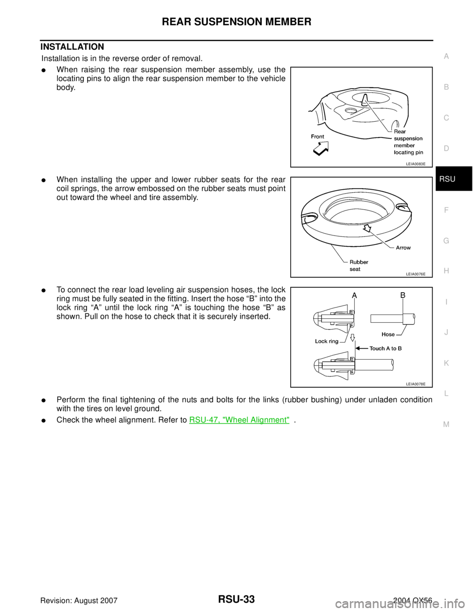
INSTALLATION
Installation is in the reverse order of removal.
�When raising the rear suspension member assembly, use the
locating pins to align the rear suspension member to the vehicle
body.
�When installing the upper and lower rubber seats for the rear
coil springs, the arrow embossed on the rubber seats must point
out toward the wheel and tire assembly.
�To connect the rear load leveling air suspension hoses, the lock
ring must be fully seated in the fitting. Insert the hose “B” into the
lock ring “A” until the lock ring “A” is touching the hose “B” as
shown. Pull on the hose to check that it is securely inserted.
�Perform the final tightening of the nuts and bolts for the links (rubber bushing) under unladen condition
with the tires on level ground.
�Check the wheel alignment. Refer to RSU-47, "Wheel Alignment" .
LEIA0083E
LEIA0076E
LEIA0078E
Page 2895 of 3371
RSU-36
SUSPENSION ARM
Revision: August 20072004 QX56
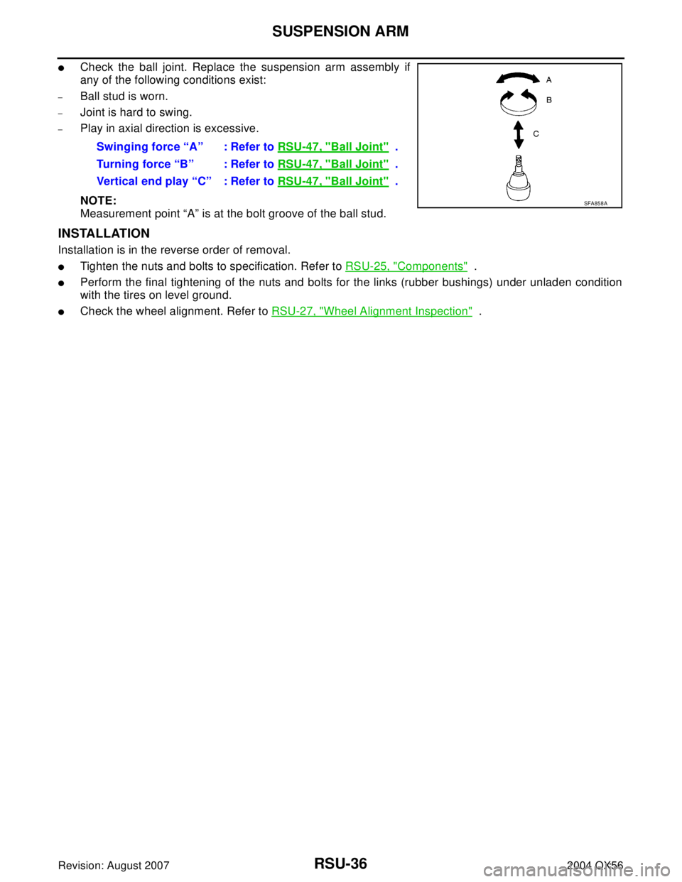
�Check the ball joint. Replace the suspension arm assembly if
any of the following conditions exist:
–Ball stud is worn.
–Joint is hard to swing.
–Play in axial direction is excessive.
NOTE:
Measurement point “A” is at the bolt groove of the ball stud.
INSTALLATION
Installation is in the reverse order of removal.
�Tighten the nuts and bolts to specification. Refer to RSU-25, "Components" .
�Perform the final tightening of the nuts and bolts for the links (rubber bushings) under unladen condition
with the tires on level ground.
�Check the wheel alignment. Refer to RSU-27, "Wheel Alignment Inspection" . Swinging force “A” : Refer to RSU-47, "
Ball Joint" .
Turning force “B” : Refer to RSU-47, "
Ball Joint" .
Vertical end play “C” : Refer to RSU-47, "
Ball Joint" .
SFA858A
Page 2897 of 3371
RSU-38
FRONT LOWER LINK
Revision: August 20072004 QX56
NOTE:
Measurement point “A” is at the bolt groove of the ball stud.
INSTALLATION
Installation is in the reverse order of removal.
�Tighten the nuts and bolts to specification. Refer to RSU-25, "Components" .
�Perform the final tightening of the front lower link nuts and bolts (with rubber bushings) under unladen
condition with tires on level ground.
�Check the wheel alignment. Refer to RSU-27, "Wheel Alignment Inspection" .
Page 2899 of 3371
RSU-40
REAR LOWER LINK & COIL SPRING
Revision: August 20072004 QX56
8. Remove the rear lower link adjusting bolt and nut from the rear
suspension member using power tool, then remove the rear
lower link.
INSPECTION AFTER REMOVAL
Check the coil spring and rubber seats for deformation, cracks, or other damage and replace if necessary.
INSTALLATION
Installation is in the reverse order of removal.
�Tighten the nuts and bolts to specification. Refer to RSU-25, "Components" .
�When installing the upper and lower rubber seats for the rear
coil springs, the arrow embossed on the rubber seats must point
out toward the wheel and tire assembly.
�After installing the rear lower link and coil spring, check the
wheel alignment and adjust if necessary. Refer to RSU-27,
"Wheel Alignment Inspection" .
LEIA0009E
LEIA0076E
Page 2906 of 3371
SERVICE DATA AND SPECIFICATIONS (SDS)
RSU-47
C
D
F
G
H
I
J
K
L
MA
B
RSU
Revision: August 20072004 QX56
SERVICE DATA AND SPECIFICATIONS (SDS)PFP:00030
Wheel AlignmentEES0011X
Ball JointEES0011Y
Camber
Degree minute (decimal degree)Minimum 0° 0′ (0°)
Nominal - 0° 30′ (-0.5°)
Maximum - 1° 0′ (-1.0°)
Cross camber 0° 45′ (0.75°)
To e - i nDistance (A - B)Minimum 0 mm (0 in)
Nominal 3.3 mm (0.130 in)
Maximum 6.6 mm (0.260 in)
Cross toe 2 mm (0.079 in)
Angle (left and right)
Degree minute (decimal degree)Minimum 0° 0′ (0°)
Nominal 0° 7′ (0.11°)
Maximum 0° 14′ (0.22°)
Cross toe 0° 8′ (0.14°)
SFA234AC
Swinging force “A” (measurement point is at the bolt groove of the ball stud) 11.4 - 145.5 N (1.16 - 14.8 kg, 2.56 - 32.7 lb)
Turning torque “B” 0.5 - 6.4 N·m (0.06 - 0.65 kg-m, 5 - 56 in-lb)
Vertical end play “C”0 mm (0 in)
SFA858A
.
If the wheels are rotated m")


RSU-47
C
D
F
G
H
I
J
K
L
MA
B
RSU
Revision: August 20072004 QX56
SERVICE DATA AND SPECIFICATIONS (SDS)PFP:00030
Wheel AlignmentEES0011X
Ball JointEES0011Y
Camber")