Page 3231 of 3371
TF-106
TRANSFER MOTOR
Revision: August 20072004 QX56
TRANSFER MOTORPFP:00000
Removal and InstallationEDS0018R
REMOVAL
1. Disconnect transfer motor harness connector.
2. Remove breather pipe from transfer motor.
3. Remove bolts to detach transfer motor.
NOTE:
After removing transfer motor, be sure to replace O-ring with
new one.
INSTALLATIONEDS0018S
1. Apply ATF or petroleum jelly to new O-ring.
NOTE:
Do not reuse O-ring.
2. Align width across flat-notch with oil pump groove, and install
transfer motor.
3. Tighten bolts.
4. Install breather pipe to transfer motor.
5. Connect transfer motor harness connector.
SDIA2133E
Transfer motor bolts : 45 N·m (4.6 kg-m, 33 ft-lb)
SDIA2185E
Page 3234 of 3371

REMOVAL AND INSTALLATION
TF-109
C
E
F
G
H
I
J
K
L
MA
B
TF
Revision: August 20072004 QX56
REMOVAL AND INSTALLATIONPFP:00000
RemovalEDS0018V
1. Remove A/T undercover using power tools.
2. Remove center exhaust tube and muffler. Refer to EX-3, "
EXHAUST SYSTEM" .
3. Remove front and rear propeller shafts. Refer to PR-5, "
REMOVAL" (front) and PR-9, "REMOVAL"
(rear).
CAUTION:
Be careful not to damage spline, sleeve yoke and rear oil seal when removing the rear propeller
shaft
NOTE:
Insert a plug into rear oil seal after removing rear propeller shaft.
4. Remove A/T mount bolts. Refer to AT-255, "
TRANSMISSION ASSEMBLY" .
5. Position two suitable jacks under A/T and transfer assembly.
6. Remove crossmember. Refer to TF-109, "
REMOVAL AND INSTALLATION" .
WAR NIN G:
Support A/T and transfer assembly using two suitable jacks while removing crossmember.
7. Disconnect the ATP switch, neutral 4LO switch, wait detection switch, transfer motor and transfer control
device electrical connectors.
8. Remove breather hoses from the actuator, transfer rear case and transfer motor.
9. Remove the shift actuator from the extension housing.
10. Remove transfer to A/T bolts.
WAR NIN G:
Support transfer assembly with suitable jack while removing it.
11. Remove transfer assembly.
InstallationEDS0018W
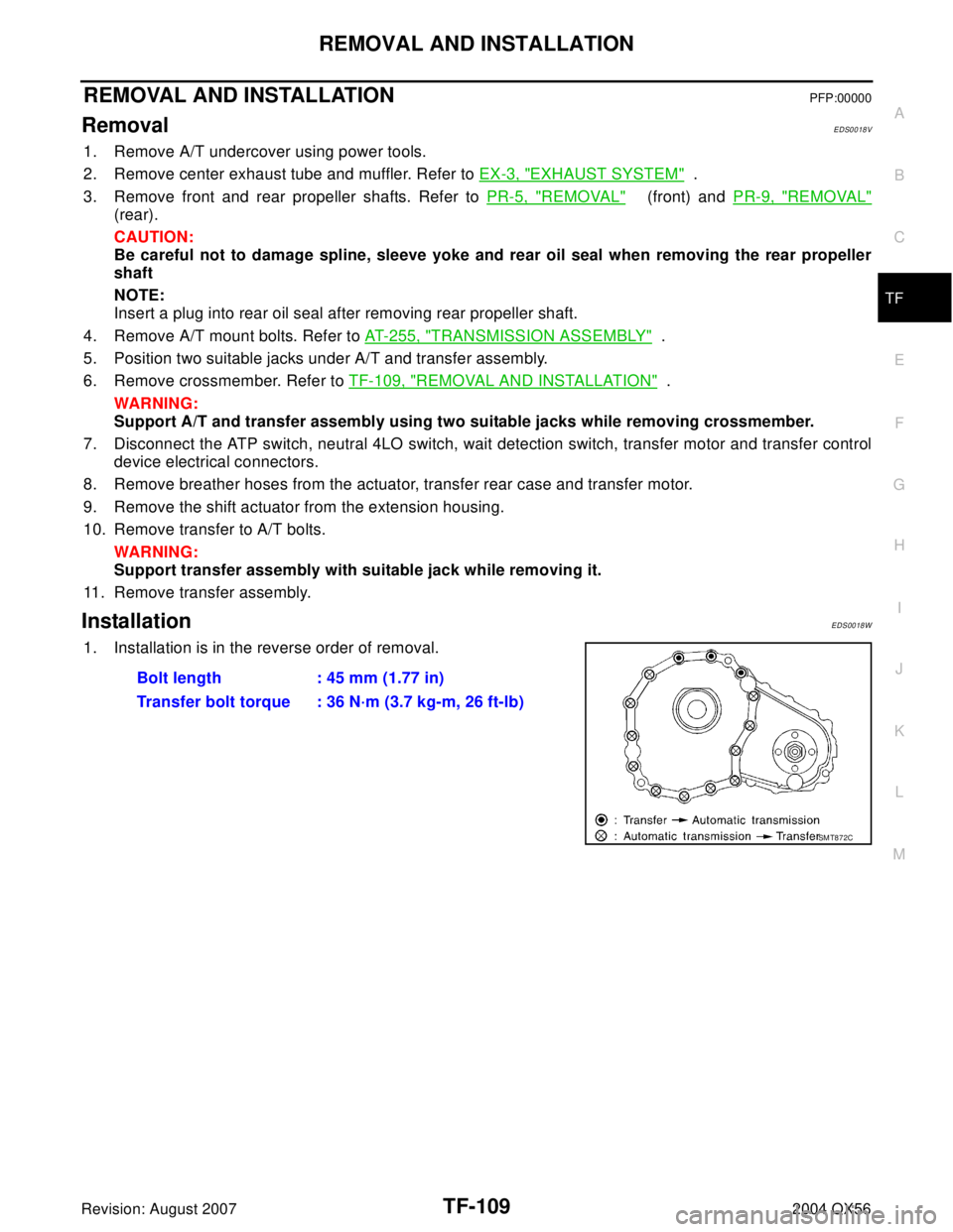
1. Installation is in the reverse order of removal.
Bolt length : 45 mm (1.77 in)
Transfer bolt torque : 36 N·m (3.7 kg-m, 26 ft-lb)
SMT872C
Page 3236 of 3371
OVERHAUL
TF-111
C
E
F
G
H
I
J
K
L
MA
B
TF
Revision: August 20072004 QX56
46. Snap ring 47. Retaining pin 48. L-H fork
49. 2-4 fork 50. Shift fork spring 51. Fork guide
52. Retainer pin 53. Shift rod
1. Dust cover 2. Oil seal 3. Rear case
4. Air breather 5. Seal ring 6. Main oil pump cover
7. Inner gear 8. Outer gear 9. Main oil pump housing
10. D-ring 11. D-ring 12. Clutch piston
13. Thrust needle bearing race 14. Oil strainer 15. O-ring
16. Snap ring 17. Control valve assembly 18. Lip seal (7 pieces)
19. Washer 20. Filler plug 21. Filler stud
22. O-ring 23. Oil filter 24. ATP switch
25 Neutral-4LO switch 26. Oil pressure check plug 27. Harness bracket
28. Stem bleeder 29. Harness bracket 30. Center case
31. Mainshaft rear bearing 32. C-ring 33. Washer holder
34. Snap ring 35. Sub oil pump housing 36. Outer gear
37. Inner gear 38. Sub oil pump cover 39. O-ring
40. Transfer motor 41. Connector bracket
SDIA2091E
Page 3248 of 3371
CENTER CASE
TF-123
C
E
F
G
H
I
J
K
L
MA
B
TF
Revision: August 20072004 QX56
SUB OIL PUMP
1. Remove bolts to detach transfer motor from center case. Then
remove O-ring from the transfer motor.
2. Remove sub oil pump cover bolts.
3. Thread two bolts (M4 x 0.8) into the holes of sub oil pump cover
as shown, and pull out to remove sub oil pump assembly.
4. Remove sub oil pump cover, outer gear, inner gear, and O-ring
from sub oil pump housing.
SDIA2133E
SDIA2134E
SMT934C
SDIA2135E
Page 3266 of 3371
CENTER CASE
TF-141
C
E
F
G
H
I
J
K
L
MA
B
TF
Revision: August 20072004 QX56
3. Apply ATF or petroleum jelly to new O-ring and install it to trans-
fer motor.
NOTE:
Do not reuse O-rings.
4. Fit double-flat end of transfer motor shaft into slot of sub-oil
pump assembly. Then tighten bolts.
CAUTION:
Be sure to install connector bracket.
MAIN OIL PUMP
1. Install inner gear and outer gear in the main oil pump housing.
Then, measure the side clearance. Refer to TF-133, "
MAIN OIL
PUMP" .
2. Install main oil pump housing, outer gear and inner gear to cen-
ter case.
3. Apply ATF or petroleum jelly to the new seal ring and install it to
main oil pump cover.
NOTE:
Do not reuse seal ring.
4. Install main oil pump cover to the center case, and install bolts.Transfer motor bolts : 45 N·m (4.6 kg-m, 33 ft-lb)
SDIA2185E
SDIA2174E
Main oil pump bolts : 7.8 N·m (0.8 kg-m, 69 in-lb)
SDIA2188E
SDIA2132E
Main oil pump cover bolts : 7.8 N·m (0.8 kg-m, 69 in-lb)
SDIA2130E