Page 2723 of 3371
PG-64
ELECTRICAL UNITS LOCATION
Revision: August 20072004 QX56
ELECTRICAL UNITS LOCATIONPFP:25230
Electrical Units LocationEKS007O0
ENGINE COMPARTMENT
WKIA2014E
Page 2724 of 3371
ELECTRICAL UNITS LOCATION
PG-65
C
D
E
F
G
H
I
J
L
MA
B
PG
Revision: August 20072004 QX56
PASSENGER COMPARTMENT
WKIA4240E
Page 2725 of 3371
PG-66
ELECTRICAL UNITS LOCATION
Revision: August 20072004 QX56
WKIA2015E
Page 2726 of 3371

ELECTRICAL UNITS LOCATION
PG-67
C
D
E
F
G
H
I
J
L
MA
B
PG
Revision: August 20072004 QX56
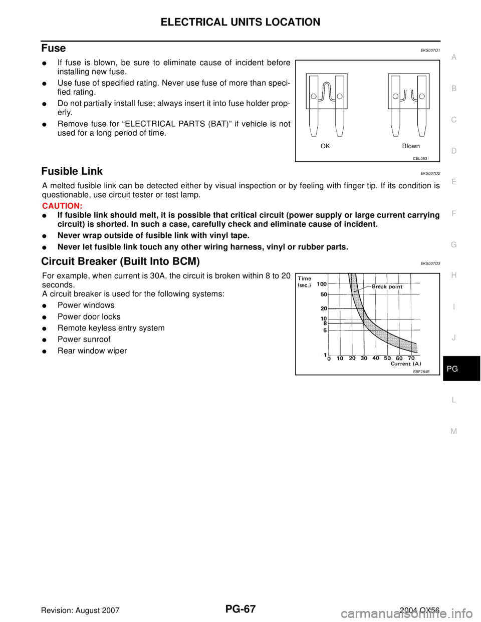
Fuse EKS007O1
�If fuse is blown, be sure to eliminate cause of incident before
installing new fuse.
�Use fuse of specified rating. Never use fuse of more than speci-
fied rating.
�Do not partially install fuse; always insert it into fuse holder prop-
erly.
�Remove fuse for “ELECTRICAL PARTS (BAT)” if vehicle is not
used for a long period of time.
Fusible Link EKS007O2
A melted fusible link can be detected either by visual inspection or by feeling with finger tip. If its condition is
questionable, use circuit tester or test lamp.
CAUTION:
�If fusible link should melt, it is possible that critical circuit (power supply or large current carrying
circuit) is shorted. In such a case, carefully check and eliminate cause of incident.
�Never wrap outside of fusible link with vinyl tape.
�Never let fusible link touch any other wiring harness, vinyl or rubber parts.
Circuit Breaker (Built Into BCM)EKS007O3
For example, when current is 30A, the circuit is broken within 8 to 20
seconds.
A circuit breaker is used for the following systems:
�Power windows
�Power door locks
�Remote keyless entry system
�Power sunroof
�Rear window wiper
CEL083
SBF 2 84 E
Page 2730 of 3371
ELECTRICAL UNITS
PG-71
C
D
E
F
G
H
I
J
L
MA
B
PG
Revision: August 20072004 QX56
ELECTRICAL UNITSPFP:23710
Terminal ArrangementEKS007O5
WKIA3542E
Page 2753 of 3371

PS-2
PRECAUTIONS
Revision: August 20072004 QX56
PRECAUTIONSPFP:00001
Precautions for Supplemental Restraint System (SRS) “AIR BAG” and “SEAT
BELT PRE-TENSIONER”
EGS000MI
The Supplemental Restraint System such as “AIR BAG” and “SEAT BELT PRE-TENSIONER”, used along
with a front seat belt, helps to reduce the risk or severity of injury to the driver and front passenger for certain
types of collision. This system includes seat belt switch inputs and dual stage front air bag modules. The SRS
system uses the seat belt switches to determine the front air bag deployment, and may only deploy one front
air bag, depending on the severity of a collision and whether the front occupants are belted or unbelted.
Information necessary to service the system safely is included in the SRS and SB section of this Service Man-
ual.
WAR NIN G:
�To avoid rendering the SRS inoperative, which could increase the risk of personal injury or death
in the event of a collision which would result in air bag inflation, all maintenance must be per-
formed by an authorized NISSAN/INFINITI dealer.
�Improper maintenance, including incorrect removal and installation of the SRS, can lead to per-
sonal injury caused by unintentional activation of the system. For removal of Spiral Cable and Air
Bag Module, see the SRS section.
�Do not use electrical test equipment on any circuit related to the SRS unless instructed to in this
Service Manual. SRS wiring harnesses can be identified by yellow and/or orange harnesses or
harness connectors.
Precautions for Steering SystemEGS000MJ
�Before disassembly, thoroughly clean the outside of the unit.
�Disassembly should be done in a clean work area. It is important to prevent the internal parts from becom-
ing contaminated by dirt or other foreign matter.
�For easier and proper assembly, place disassembled parts in order on a parts rack.
�Use nylon cloth or paper towels to clean the parts; common shop rags can leave lint that might interfere
with their operation.
�Before inspection or reassembly, carefully clean all parts with a general purpose, non-flammable solvent.
�Before assembly, apply a coat of recommended Genuine NISSAN PSF or equivalent to hydraulic parts.
Petroleum jelly may be applied to O-rings and seals. Do not use any grease.
�Replace all gaskets, seals and O-rings. Avoid damaging O-rings, seals and gaskets during installation.
Perform functional tests whenever designated.
Page 2760 of 3371
TILT SYSTEM
PS-9
C
D
E
F
H
I
J
K
L
MA
B
PS
Revision: August 20072004 QX56
TILT SYSTEMPFP:48810
Removal and InstallationEGS000N8
TILT MOTOR AND TILT SENSOR
Removal
1. Remove the steering column cover and lower driver instrument panel. Refer to IP-10, "INSTRUMENT
PANEL ASSEMBLY" .
2. Remove knee protector.
3. Disconnect the tilt sensor electrical connector.
4. Remove the two tilt sensor screws and the tilt sensor.
5. Disconnect the tilt motor electrical connector.
6. Remove the tilt motor bolt and the tilt motor.
Installation
Installation is in reverse order of removal.
NOTE:
Make sure the tab in the tilt sensor is engaged in the bracket on the tilt motor.
LGIA0022E
1. Tilt sensor 2. Tilt motor
LGIA0026E
Page 2777 of 3371

PS-26
POWER STEERING OIL PUMP
Revision: August 20072004 QX56
POWER STEERING OIL PUMPPFP:49110
On-Vehicle Inspection and ServiceEGS000MW
CHECKING RELIEF OIL PRESSURE
CAUTION:
Before starting work, confirm belt tension is proper.
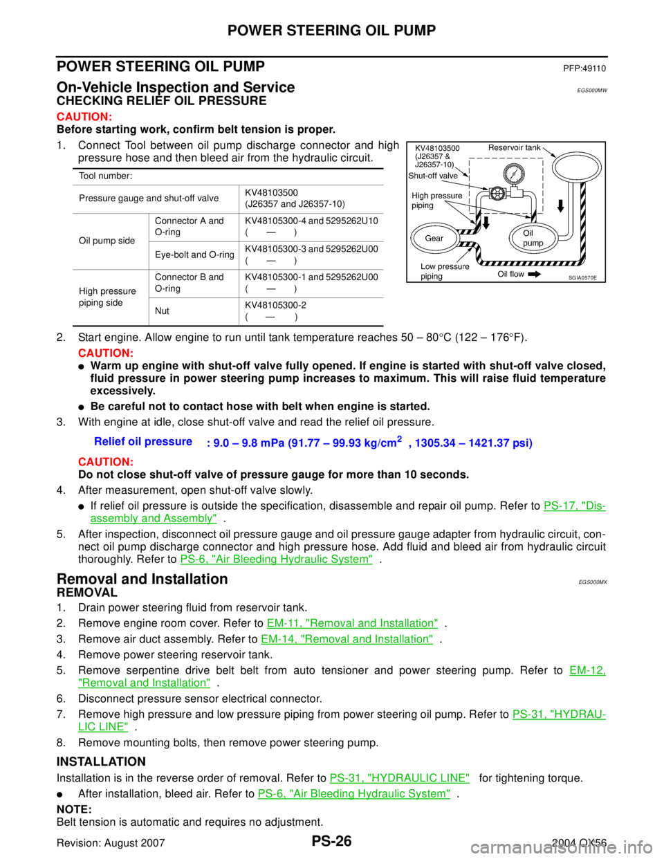
1. Connect Tool between oil pump discharge connector and high
pressure hose and then bleed air from the hydraulic circuit.
2. Start engine. Allow engine to run until tank temperature reaches 50 – 80°C (122 – 176°F).
CAUTION:
�Warm up engine with shut-off valve fully opened. If engine is started with shut-off valve closed,
fluid pressure in power steering pump increases to maximum. This will raise fluid temperature
excessively.
�Be careful not to contact hose with belt when engine is started.
3. With engine at idle, close shut-off valve and read the relief oil pressure.
CAUTION:
Do not close shut-off valve of pressure gauge for more than 10 seconds.
4. After measurement, open shut-off valve slowly.
�If relief oil pressure is outside the specification, disassemble and repair oil pump. Refer to PS-17, "Dis-
assembly and Assembly" .
5. After inspection, disconnect oil pressure gauge and oil pressure gauge adapter from hydraulic circuit, con-
nect oil pump discharge connector and high pressure hose. Add fluid and bleed air from hydraulic circuit
thoroughly. Refer to PS-6, "
Air Bleeding Hydraulic System" .
Removal and InstallationEG S0 0 0MX
REMOVAL
1. Drain power steering fluid from reservoir tank.
2. Remove engine room cover. Refer to EM-11, "
Removal and Installation" .
3. Remove air duct assembly. Refer to EM-14, "
Removal and Installation" .
4. Remove power steering reservoir tank.
5. Remove serpentine drive belt belt from auto tensioner and power steering pump. Refer to EM-12,
"Removal and Installation" .
6. Disconnect pressure sensor electrical connector.
7. Remove high pressure and low pressure piping from power steering oil pump. Refer to PS-31, "
HYDRAU-
LIC LINE" .
8. Remove mounting bolts, then remove power steering pump.
INSTALLATION
Installation is in the reverse order of removal. Refer to PS-31, "HYDRAULIC LINE" for tightening torque.
�After installation, bleed air. Refer to PS-6, "Air Bleeding Hydraulic System" .
NOTE:
Belt tension is automatic and requires no adjustment.
Tool number:
Pressure gauge and shut-off valveKV48103500
(J26357 and J26357-10)
Oil pump sideConnector A and
O-ringKV48105300-4 and 5295262U10
(—)
Eye-bolt and O-ringKV48105300-3 and 5295262U00
(—)
High pressure
piping sideConnector B and
O-ringKV48105300-1 and 5295262U00
(—)
NutKV48105300-2
( — )
Relief oil pressure
: 9.0 – 9.8 mPa (91.77 – 99.93 kg/cm2 , 1305.34 – 1421.37 psi)
SGIA0570E