Page 2447 of 3371
LT-16
HEADLAMP (FOR USA)
Revision: August 20072004 QX56
Preliminary CheckEKS0079X
CHECK POWER SUPPLY AND GROUND CIRCUIT
1. CHECK FUSES OR FUSIBLE LINK
Check for blown fuses or fusible link.
Refer to LT- 1 0 , "
Wiring Diagram — H/LAMP —" .
OK or NG
OK >> GO TO 2.
NG >> If fuse is blown, be sure to eliminate cause of blown fuse before installing new fuse. Refer to PG-
4, "POWER SUPPLY ROUTING CIRCUIT" .
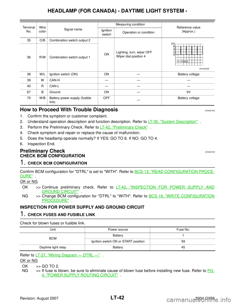
2. CHECK POWER SUPPLY CIRCUIT
1. Disconnect BCM connectors.
2. Check voltage between BCM harness connector and ground.
OK or NG
OK >> GO TO 3.
NG >> Check harness for open between BCM and fuse or fus-
ible link.
Unit Power source Fuse No.
BCMBattery f
Ignition switch ON or START position 59
IPDM E/R Battery34
35
40
41
53
BCM
(–)Ignition switch position
(+)
OFF ACC ON
ConnectorTe r m i n a l
(wire color)
M18 38 (W/L)
Ground0V 0VBattery
voltage
M20 70 (W/B)Battery
voltageBattery
voltageBattery
voltage
WKIA1436E
Page 2468 of 3371
HEADLAMP (FOR CANADA) - DAYTIME LIGHT SYSTEM -
LT-37
C
D
E
F
G
H
I
J
L
MA
B
LT
Revision: August 20072004 QX56
Wiring Diagram — DTRL —EKS007AE
WKWA3110E
Page 2473 of 3371

LT-42
HEADLAMP (FOR CANADA) - DAYTIME LIGHT SYSTEM -
Revision: August 20072004 QX56
How to Proceed With Trouble DiagnosisEKS007AG
1. Confirm the symptom or customer complaint.
2. Understand operation description and function description. Refer to LT-35, "
System Description" .
3. Perform the Preliminary Check. Refer to LT-42, "
Preliminary Check" .
4. Check symptom and repair or replace the cause of malfunction.
5. Does the headlamp operate normally? If YES: GO TO 6. If NO: GO TO 4.
6. Inspection End.
Preliminary CheckEKS007AH
CHECK BCM CONFIGURATION
1. CHECK BCM CONFIGURATION
Confirm BCM configuration for "DTRL" is set to "WITH". Refer to BCS-13, "
READ CONFIGURATION PROCE-
DURE" .
OK or NG
OK >> Continue preliminary check. Refer to LT- 4 2 , "INSPECTION FOR POWER SUPPLY AND
GROUND CIRCUIT" .
NG >> Change BCM configuration for "DTRL" to "WITH". Refer to BCS-16, "
WRITE CONFIGURATION
PROCEDURE" .
INSPECTION FOR POWER SUPPLY AND GROUND CIRCUIT
1. CHECK FUSES AND FUSIBLE LINK
Check for blown fuses or fusible link.
Refer to LT- 3 7 , "
Wiring Diagram — DTRL —" .
OK or NG
OK >> GO TO 2.
NG >> If fuse is blown, be sure to eliminate cause of blown fuse before installing new fuse. Refer to PG-
4, "POWER SUPPLY ROUTING CIRCUIT" .
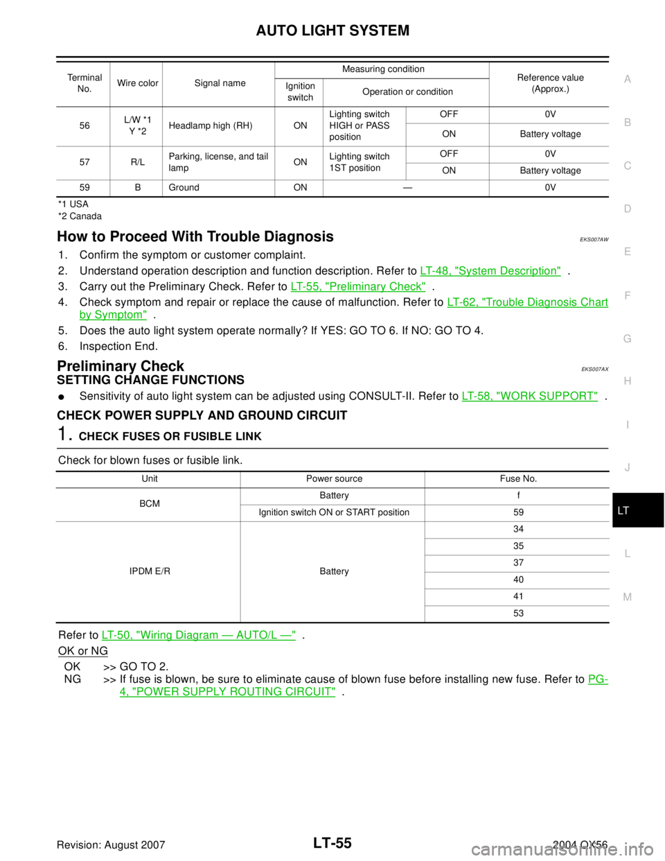
35 O/B Combination switch output 2
ONLighting, turn, wiper OFF
Wiper dial position 4
36 R/W Combination switch output 1
38 W/L Ignition switch (ON) ON — Battery voltage
39 W CAN-H — — —
40 R CAN-L — — —
67 B Ground ON — 0V
70 W/B Battery power supply (fusible
link)OFF
—Battery voltage Terminal
No.Wire
colorSignal nameMeasuring condition
Reference value
(Approx.) Ignition
switchOperation or condition
SKIA5292E
Unit Power source Fuse No.
BCMBattery f
Ignition switch ON or START position 59
Daytime light relay Battery 45
Page 2481 of 3371
LT-50
AUTO LIGHT SYSTEM
Revision: August 20072004 QX56
Wiring Diagram — AUTO/L —EKS007AT
WKWA3112E
Page 2486 of 3371

AUTO LIGHT SYSTEM
LT-55
C
D
E
F
G
H
I
J
L
MA
B
LT
Revision: August 20072004 QX56
*1 USA
*2 Canada
How to Proceed With Trouble DiagnosisEKS007AW
1. Confirm the symptom or customer complaint.
2. Understand operation description and function description. Refer to LT- 4 8 , "
System Description" .
3. Carry out the Preliminary Check. Refer to LT- 5 5 , "
Preliminary Check" .
4. Check symptom and repair or replace the cause of malfunction. Refer to LT- 6 2 , "
Trouble Diagnosis Chart
by Symptom" .
5. Does the auto light system operate normally? If YES: GO TO 6. If NO: GO TO 4.
6. Inspection End.
Preliminary CheckEKS007AX
SETTING CHANGE FUNCTIONS
�Sensitivity of auto light system can be adjusted using CONSULT-II. Refer to LT-58, "WORK SUPPORT" .
CHECK POWER SUPPLY AND GROUND CIRCUIT
1. CHECK FUSES OR FUSIBLE LINK
Check for blown fuses or fusible link.
Refer to LT- 5 0 , "
Wiring Diagram — AUTO/L —" .
OK or NG
OK >> GO TO 2.
NG >> If fuse is blown, be sure to eliminate cause of blown fuse before installing new fuse. Refer to PG-
4, "POWER SUPPLY ROUTING CIRCUIT" .
56L/W *1
Y *2Headlamp high (RH) ONLighting switch
HIGH or PASS
positionOFF 0V
ON Battery voltage
57 R/LParking, license, and tail
lampONLighting switch
1ST positionOFF 0V
ON Battery voltage
59 B Ground ON — 0V Terminal
No.Wire color Signal nameMeasuring condition
Reference value
(Approx.) Ignition
switchOperation or condition
Unit Power source Fuse No.
BCMBattery f
Ignition switch ON or START position 59
IPDM E/R Battery34
35
37
40
41
53
Page 2497 of 3371
LT-66
HEADLAMP AIMING CONTROL
Revision: August 20072004 QX56
Wiring Diagram — H/AIM —EKS007RW
WKWA3113E
Page 2502 of 3371
FRONT FOG LAMP
LT-71
C
D
E
F
G
H
I
J
L
MA
B
LT
Revision: August 20072004 QX56
Wiring Diagram — F/FOG —EKS007B7
WKWA3114E
Page 2506 of 3371

FRONT FOG LAMP
LT-75
C
D
E
F
G
H
I
J
L
MA
B
LT
Revision: August 20072004 QX56
Preliminary CheckEKS007BB
CHECK POWER SUPPLY AND GROUND CIRCUIT
1. CHECK FUSES OR FUSIBLE LINK
Check for blown fuses or fusible link.
Refer to LT- 7 1 , "
Wiring Diagram — F/FOG —" .
OK or NG
OK >> GO TO 2.
NG >> If fuse is blown, be sure to eliminate cause of blown fuse before installing new fuse. Refer to PG-
4, "POWER SUPPLY ROUTING CIRCUIT" .
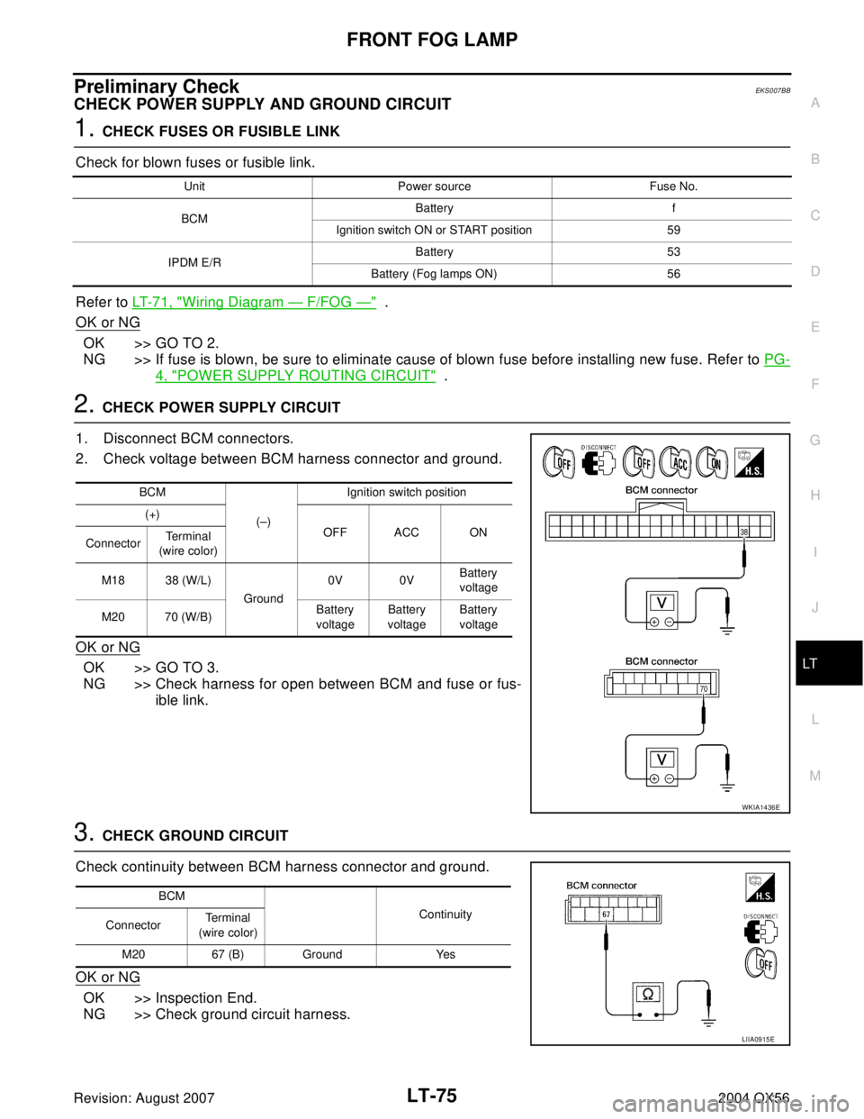
2. CHECK POWER SUPPLY CIRCUIT
1. Disconnect BCM connectors.
2. Check voltage between BCM harness connector and ground.
OK or NG
OK >> GO TO 3.
NG >> Check harness for open between BCM and fuse or fus-
ible link.
3. CHECK GROUND CIRCUIT
Check continuity between BCM harness connector and ground.
OK or NG
OK >> Inspection End.
NG >> Check ground circuit harness.
Unit Power source Fuse No.
BCMBattery f
Ignition switch ON or START position 59
IPDM E/RBattery 53
Battery (Fog lamps ON) 56
BCM
(–)Ignition switch position
(+)
OFF ACC ON
ConnectorTerminal
(wire color)
M18 38 (W/L)
Ground0V 0VBattery
voltage
M20 70 (W/B)Battery
voltageBattery
voltageBattery
voltage
WKIA1436E
BCM
Continuity
ConnectorTe r m i n a l
(wire color)
M20 67 (B) Ground Yes
LIIA0915E