Page 3219 of 3371

TF-94
TROUBLE DIAGNOSES FOR SYMPTOMS
Revision: August 20072004 QX56
Symptom 9. 4WD System Does Not Operate (The Vehicle Cannot Be Put Into
4WD Mode-Hydraulic System Failure)
EDS0018M
1. CHECK INPUT SIGNAL
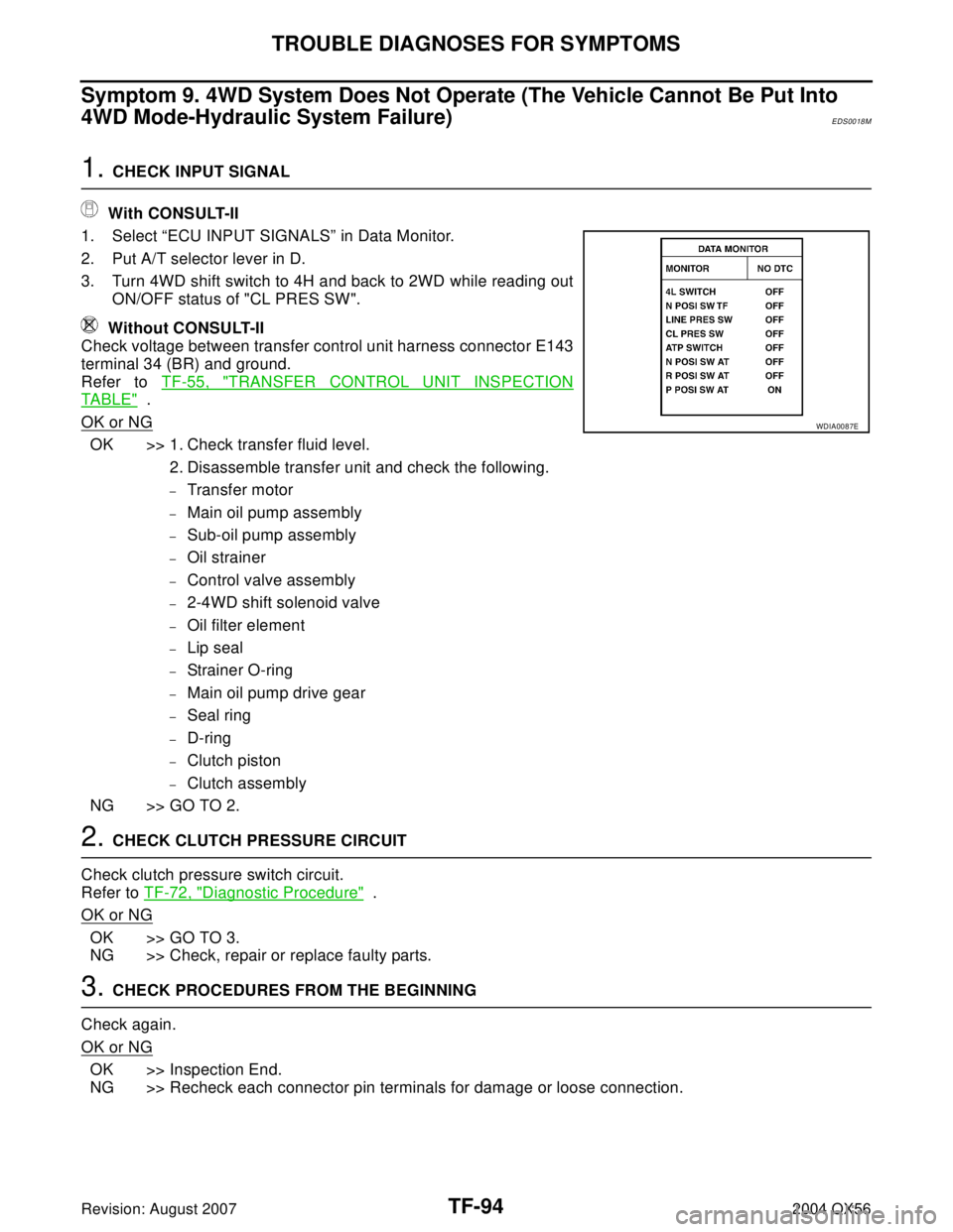
With CONSULT-II
1. Select “ECU INPUT SIGNALS” in Data Monitor.
2. Put A/T selector lever in D.
3. Turn 4WD shift switch to 4H and back to 2WD while reading out
ON/OFF status of "CL PRES SW".
Without CONSULT-II
Check voltage between transfer control unit harness connector E143
terminal 34 (BR) and ground.
Refer to TF-55, "
TRANSFER CONTROL UNIT INSPECTION
TABLE" .
OK or NG
OK >> 1. Check transfer fluid level.
2. Disassemble transfer unit and check the following.
–Transfer motor
–Main oil pump assembly
–Sub-oil pump assembly
–Oil strainer
–Control valve assembly
–2-4WD shift solenoid valve
–Oil filter element
–Lip seal
–Strainer O-ring
–Main oil pump drive gear
–Seal ring
–D-ring
–Clutch piston
–Clutch assembly
NG >> GO TO 2.
2. CHECK CLUTCH PRESSURE CIRCUIT
Check clutch pressure switch circuit.
Refer to TF-72, "
Diagnostic Procedure" .
OK or NG
OK >> GO TO 3.
NG >> Check, repair or replace faulty parts.
3. CHECK PROCEDURES FROM THE BEGINNING
Check again.
OK or NG
OK >> Inspection End.
NG >> Recheck each connector pin terminals for damage or loose connection.
WDIA0087E
Page 3246 of 3371
CENTER CASE
TF-121
C
E
F
G
H
I
J
K
L
MA
B
TF
Revision: August 20072004 QX56
8. Remove O-rings from each solenoid valve, switch and terminal body.
9. Place control valve with lower body facing up, remove two
mounting bolts, and then remove lower body and separator plate
from upper body.
CAUTION:
Be careful not to drop relief balls. Detach lower body care-
fully.
10. Make sure reverse balls, relief balls and relief springs, accumu-
lator pistons and valve springs are securely installed as shown,
and remove them.
11. Remove retainer plates.
12. Remove each plug (2), control valve (3) and spring (4) from the
upper body (5).
SDIA2125E
SDIA2126E
SDIA2127E
WDIA0284E
Page 3261 of 3371
TF-136
FRONT CASE
Revision: August 20072004 QX56
FRONT CASEPFP:33107
AssemblyEDS00193
PLANETARY CARRIER, SUN GEAR AND INTERNAL GEAR
1. Install new oil seal until it is seated flush with end face of the
front case, using Tool.
NOTE:
�Before installing, apply ATF or petroleum jelly to new oil seal
lip.
�Do not reuse oil seal.
2. Install internal gear with its groove facing snap ring into front
case. Then secure it with new snap ring.
NOTE:
Do not reuse snap ring.
3. Set mainshaft front bearing into front case and install, using
Tool.
4. Install new snap ring into front case.
NOTE:
Do not reuse snap ring.
5. Install shift cross to front case.Tool number : KV38100500 ( — )
SDIA2177E
WDIA0100E
Tool number : ST30720000 (J-25405)
SDIA2172E
SDIA2171E
Page 3264 of 3371

FRONT CASE
TF-139
C
E
F
G
H
I
J
K
L
MA
B
TF
Revision: August 20072004 QX56
17. Install shift rod assembly to front case assembly. Refer to TF-139, "SHIFT ROD ASSEMBLY" .
SHIFT ROD ASSEMBLY
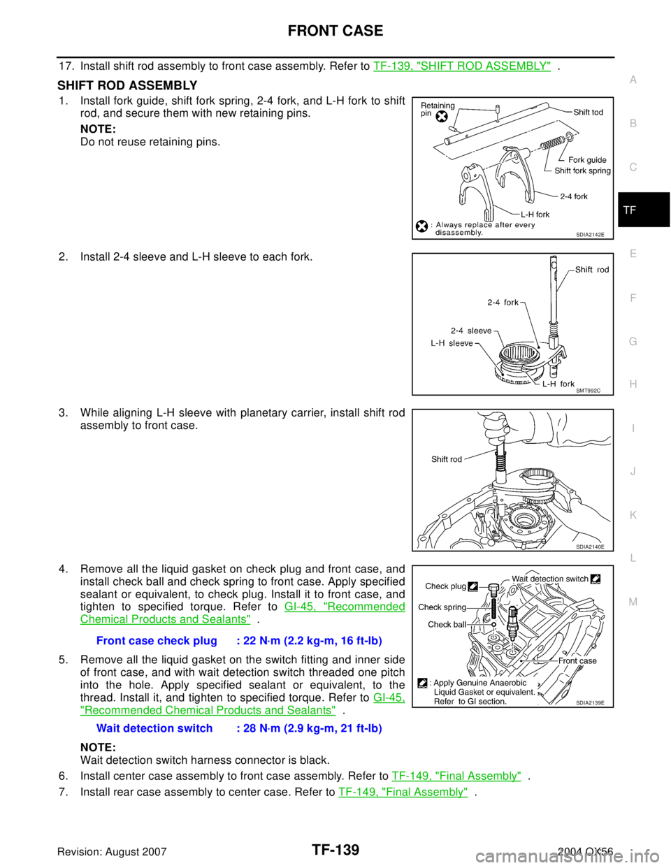
1. Install fork guide, shift fork spring, 2-4 fork, and L-H fork to shift
rod, and secure them with new retaining pins.
NOTE:
Do not reuse retaining pins.
2. Install 2-4 sleeve and L-H sleeve to each fork.
3. While aligning L-H sleeve with planetary carrier, install shift rod
assembly to front case.
4. Remove all the liquid gasket on check plug and front case, and
install check ball and check spring to front case. Apply specified
sealant or equivalent, to check plug. Install it to front case, and
tighten to specified torque. Refer to GI-45, "
Recommended
Chemical Products and Sealants" .
5. Remove all the liquid gasket on the switch fitting and inner side
of front case, and with wait detection switch threaded one pitch
into the hole. Apply specified sealant or equivalent, to the
thread. Install it, and tighten to specified torque. Refer to GI-45,
"Recommended Chemical Products and Sealants" .
NOTE:
Wait detection switch harness connector is black.
6. Install center case assembly to front case assembly. Refer to TF-149, "
Final Assembly" .
7. Install rear case assembly to center case. Refer to TF-149, "
Final Assembly" .
SDIA2142E
SMT992C
SDIA2140E
Front case check plug : 22 N·m (2.2 kg-m, 16 ft-lb)
Wait detection switch : 28 N·m (2.9 kg-m, 21 ft-lb)
SDIA2139E
Page 3268 of 3371

CENTER CASE
TF-143
C
E
F
G
H
I
J
K
L
MA
B
TF
Revision: August 20072004 QX56
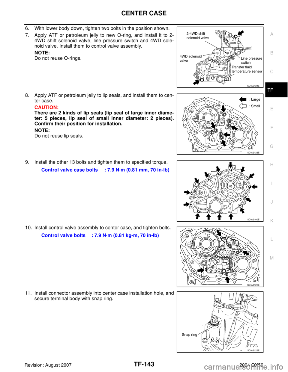
6. With lower body down, tighten two bolts in the position shown.
7. Apply ATF or petroleum jelly to new O-ring, and install it to 2-
4WD shift solenoid valve, line pressure switch and 4WD sole-
noid valve. Install them to control valve assembly.
NOTE:
Do not reuse O-rings.
8. Apply ATF or petroleum jelly to lip seals, and install them to cen-
ter case.
CAUTION:
There are 2 kinds of lip seals (lip seal of large inner diame-
ter: 5 pieces, lip seal of small inner diameter: 2 pieces).
Confirm their position for installation.
NOTE:
Do not reuse lip seals.
9. Install the other 13 bolts and tighten them to specified torque.
10. Install control valve assembly to center case, and tighten bolts.
11. Install connector assembly into center case installation hole, and
secure terminal body with snap ring.
SDIA2124E
SDIA2123E
Control valve case bolts : 7.9 N·m (0.81 mm, 70 in-lb)
SDIA2100E
Control valve bolts : 7.9 N·m (0.81 kg-m, 70 in-lb)
SDIA2121E
SDIA2122E
Page 3270 of 3371

CENTER CASE
TF-145
C
E
F
G
H
I
J
K
L
MA
B
TF
Revision: August 20072004 QX56
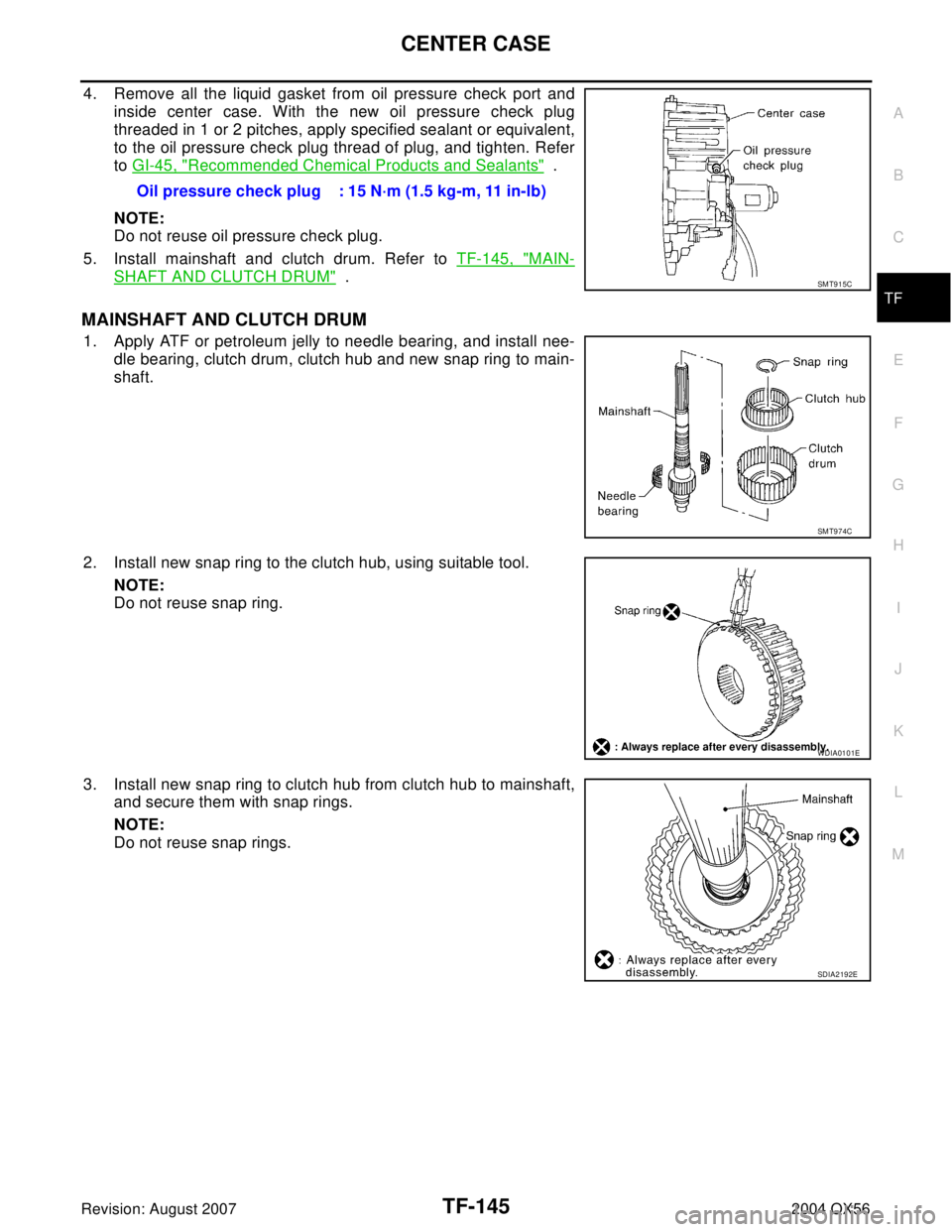
4. Remove all the liquid gasket from oil pressure check port and
inside center case. With the new oil pressure check plug
threaded in 1 or 2 pitches, apply specified sealant or equivalent,
to the oil pressure check plug thread of plug, and tighten. Refer
to GI-45, "
Recommended Chemical Products and Sealants" .
NOTE:
Do not reuse oil pressure check plug.
5. Install mainshaft and clutch drum. Refer to TF-145, "
MAIN-
SHAFT AND CLUTCH DRUM" .
MAINSHAFT AND CLUTCH DRUM
1. Apply ATF or petroleum jelly to needle bearing, and install nee-
dle bearing, clutch drum, clutch hub and new snap ring to main-
shaft.
2. Install new snap ring to the clutch hub, using suitable tool.
NOTE:
Do not reuse snap ring.
3. Install new snap ring to clutch hub from clutch hub to mainshaft,
and secure them with snap rings.
NOTE:
Do not reuse snap rings.Oil pressure check plug : 15 N·m (1.5 kg-m, 11 in-lb)
SMT915C
SMT974C
WDIA0101E
SDIA2192E
Page 3274 of 3371
ASSEMBLY
TF-149
C
E
F
G
H
I
J
K
L
MA
B
TF
Revision: August 20072004 QX56
ASSEMBLYPFP:00030
Final AssemblyEDS00195
1. Install C-rings to mainshaft.
2. Set washer holder on mainshaft, and secure it with new snap
ring.
NOTE:
Do not reuse snap ring.
3. Apply specified Anaerobic Liquid Gasket or equivalent to the
entire center case mounting surface of front case assembly as
shown. Refer to GI-45, "
Recommended Chemical Products and
Sealants" .
NOTE:
Remove all foreign materials such as water, oil and grease from
center case and front case mating surfaces.
SDIA2201E
SDIA2104E
SDIA2202E
Page 3295 of 3371
WT-16
TROUBLE DIAGNOSES
Revision: August 20072004 QX56
CONSULT-II Function (BCM)EES001PT
CONSULT-II can display each diagnostic item using the diagnostic test modes shown following.
BCM
diagnostic test itemDiagnostic mode Description
Inspection by partWORK SUPPORTSupports inspections and adjustments. Commands are transmit-
ted to the BCM for setting the status suitable for required opera-
tion, input/output signals are received from the BCM and received
data is displayed.
DATA MONITOR Displays BCM input/output data in real time.
ACTIVE TESTOperation of electrical loads can be checked by sending drive sig-
nal to them.
SELF-DIAG RESULTS Displays BCM self-diagnosis results.
CAN DIAG SUPPORT MNTRThe result of transmit/receive diagnosis of CAN communication
can be read.
ECU PART NUMBER BCM part number can be read.
CONFIGURATION Performs BCM configuration read/write functions.