Page 387 of 3371
AT-316
ASSEMBLY
Revision: August 20072004 QX56
33. Install bearing race in output shaft.
34. Install rear extension assembly (2WD models) or adapter case assembly (4WD models) according to the
following procedures.
a.2WD models
i. Apply recommended sealant (Genuine Anaerobic Liquid Gasket
or equivalent. Refer to GI-45, "
Recommended Chemical Prod-
ucts and Sealants" .) to rear extension assembly as shown in
illustration.
CAUTION:
Complete remove all moisture, oil and old sealant, etc.
From the transmission case and rear extension assembly
mounting surfaces.
ii. Install rear extension assembly to transmission case.
iii. Install bracket.
iv. Tighten rear extension assembly mounting bolts to specified
torque.
CAUTION:
Do not reuse self-sealing bolt.
SCIA5245E
SCIA5212E
SCIA5029E
Rear extension assembly mounting bolt:
: 52 N·m (5.3 kg-m, 38 ft-lb)
Self-sealing bolt:
: 61 N·m (6.2 kg-m, 45 ft-lb)
SCIA5349E
Page 388 of 3371
ASSEMBLY
AT-317
D
E
F
G
H
I
J
K
L
MA
B
AT
Revision: August 20072004 QX56
b.4WD models
i. Install gasket to transmission case.
CAUTION:
�Do not reuse gasket.
�Complete remove all moisture, oil and old gasket, etc.
From the transmission case and adapter case assembly
mounting surfaces.
ii. Install adapter case assembly to transmission case.
iii. Install bracket.
iv. Tighten adapter case assembly mounting bolts to specified
torque.
CAUTION:
Do not reuse self-sealing bolt.
35. Install needle bearing in drum support edge surface.
CAUTION:
Apply petroleum jelly to needle bearing.
SCIA5231E
SCIA5205E
Adapter case assembly mounting bolt:
: 52 N·m (5.3 kg-m, 38 ft-lb)
Self-sealing bolt:
: 61 N·m (6.2 kg-m, 45 ft-lb)
SCIA5203E
SCIA5198E
Page 1048 of 3371
![INFINITI QX56 2004 Factory Service Manual TROUBLE DIAGNOSIS
BRC-35
[VDC/TCS/ABS]
C
D
E
G
H
I
J
K
L
MA
B
BRC
Revision: August 20072004 QX56
×: Applicable
–: Not applicableVDC SIGNAL
(ON/OFF)––×VDC operation (ON/OFF) status is
displaye](/manual-img/42/57034/w960_57034-1047.png "INFINITI QX56 2004 Factory Service Manual TROUBLE DIAGNOSIS
BRC-35
[VDC/TCS/ABS]
C
D
E
G
H
I
J
K
L
MA
B
BRC
Revision: August 20072004 QX56
×: Applicable
–: Not applicableVDC SIGNAL
(ON/OFF)––×VDC operation (ON/OFF) status is
displaye")
TROUBLE DIAGNOSIS
BRC-35
[VDC/TCS/ABS]
C
D
E
G
H
I
J
K
L
MA
B
BRC
Revision: August 20072004 QX56
×: Applicable
–: Not applicableVDC SIGNAL
(ON/OFF)––×VDC operation (ON/OFF) status is
displayed.
EBD WARN LAMP – –×Brake warning lamp (ON/OFF) sta-
tus is displayed.
SLCT LVR POSI×××Shift position judged by PNP switch
signal.
R POSI SIG – –×Shift position judged by PNP switch
signal.
4WD FAIL REQ – –×The state of 4WD controller is dis-
played by CAN communication sig-
nal.
2WD/4WD – –×It recognizes on software whether it
is 2WD and whether it is in 4WD
state.
BST OPER SIG – –×Active booster operation (ON/OFF)
status is displayed.
PRESS SENSOR×–×Brake pressure detected by pres-
sure sensor is displayed.
CRANKING SIG – –×The input state of the key SW
START position signal is displayed.
PRESS SEN 2 – –×Brake pressure detected by pres-
sure sensor is displayed.
DELTA S SEN – –×The amount of stroke sensor move-
ments in the active booster
detected by DELTA S SEN is dis-
played.
RELEASE SW NO – –×Release switch signal (ON/OFF)
status is displayed. "ON" indicates
that the brake pedal is depressed.
"OFF" is that the brake pedal is
released.
RELEASE SW NC – –×Release switch signal (ON/OFF)
status is displayed. "OFF" indi-
cates that the brake pedal is
depressed on. "ON" is that the
brake pedal is released.
OHB FAIL – –×OHB fail status is displayed.
HBA FAIL – –×HBA fail status is displayed.
OHB SIG – –×OHB operation (ON/OFF) status is
displayed.
HBA SIG – –×HBA operation (ON/OFF) status is
displayed.
PRES CTRL ACC – –×Pressure control state (ON/OFF) is
displayed. It is applied only to an
ICC vehicle.
PRES FAIL ACC – –×Pressure control fail state (ON/
OFF) is displayed. It is applied only
to an ICC vehicle.
STP OFF RLY – –×Stop lamp relay signal (ON/OFF)
status is displayed. Item
(Unit)Data monitor item selection
Remarks
ECU INPUT
SIGNALSMAIN
SIGNALSSELECTION
FROM MENU
Page 1140 of 3371
WARNING LAMPS
DI-37
C
D
E
F
G
H
I
J
L
MA
B
DI
Revision: August 20072004 QX56
4WD Models
WKWA3061E
Page 2065 of 3371

FSU-6
ON-VEHICLE SERVICE
Revision: August 20072004 QX56
ON-VEHICLE SERVICEPFP:00000
Front Suspension PartsEES0010I
Check front suspension parts for excessive play, cracks, wear and
other damage.
�Shake each front wheel to check for excessive play.
If looseness is noted, inspect wheel bearing end play, then
check ball joint end play. Refer to FSU-15, "
Inspection" .
�Make sure that the cotter pin is inserted (4WD only).
�Retighten all nuts and bolts to the specified torque.
�Check shock absorber for oil leakage and other damage.
�Check suspension ball joint for grease leakage and ball joint
dust cover for cracks and other damage.
Front Wheel AlignmentEES0010J
PRELIMINARY INSPECTION
WAR NIN G:
Always adjust the alignment with the vehicle on a flat surface.
NOTE:
If alignment is out of specification, inspect and replace any damaged or worn rear suspension parts before
making any adjustments.
1. Check and adjust the wheel alignment with the vehicle under unladen conditions. “Unladen conditions”
means that the fuel, coolant, and lubricant are full; and that the spare tire, jack, hand tools and mats are in
their designated positions.
2. Check the tires for incorrect air pressure and excessive wear.
3. Check the wheels for run out and damage. Refer to WT-4, "
Inspection" .
4. Check the wheel bearing axial end play. Refer to FAX-5, "
WHEEL BEARING INSPECTION" .
5. Check the shock absorbers for leaks or damage.
6. Check each mounting point of the suspension components for any excessive looseness or damage.
7. Check each link, arm, and the rear suspension member for any damage.
8. Check the vehicle height. Refer to FSU-21, "
Wheelarch Height (Unladen*1 )" .
�For air leveling vehicles, verify the level using Consult-II memory register 1103 and set to 0 ± 10 mm (0
± 0.39 in) as necessary.
GENERAL INFORMATION AND RECOMMENDATIONS
1. A Four-Wheel Thrust Alignment should be performed.
�This type of alignment is recommended for any NISSAN vehicle.
�The four-wheel “thrust” process helps ensure that the vehicle is properly aligned and the steering wheel
is centered.
�The alignment machine itself should be capable of accepting any NISSAN vehicle.
�The alignment machine should be checked to ensure that it is level.
2. Make sure the alignment machine is properly calibrated.
�Your alignment machine should be regularly calibrated in order to give correct information.Suspension component torques : Refer to FSU-5,
"Components" .
SM A52 5A
SFA392B
Page 2070 of 3371
COIL SPRING AND SHOCK ABSORBER
FSU-11
C
D
F
G
H
I
J
K
L
MA
B
FSU
Revision: August 20072004 QX56
Coil Spring
�Check for cracks, deformation or other damage and replace if necessary.
�Check the free spring height.
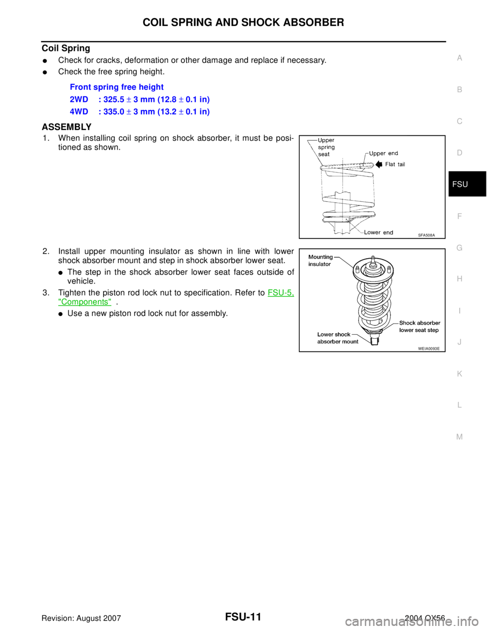
ASSEMBLY
1. When installing coil spring on shock absorber, it must be posi-
tioned as shown.
2. Install upper mounting insulator as shown in line with lower
shock absorber mount and step in shock absorber lower seat.
�The step in the shock absorber lower seat faces outside of
vehicle.
3. Tighten the piston rod lock nut to specification. Refer to FSU-5,
"Components" .
�Use a new piston rod lock nut for assembly.Front spring free height
2WD : 325.5 ± 3 mm (12.8 ± 0.1 in)
4WD : 335.0 ± 3 mm (13.2 ± 0.1 in)
SFA508A
WEIA0093E
Page 2079 of 3371

Revision: August 20072004 QX56
SERVICE DATA AND SPECIFICATIONS (SDS)PFP:00030
General Specifications (Front)EES0010T
Wheel Alignment (Unladen*1 )EES0012Y")
FSU-20
SERVICE DATA AND SPECIFICATIONS (SDS)
Revision: August 20072004 QX56
SERVICE DATA AND SPECIFICATIONS (SDS)PFP:00030
General Specifications (Front)EES0010T
Wheel Alignment (Unladen*1 )EES0012Y
*1: Fuel, radiator coolant and engine oil full. Spare tire, jack, hand tools and mats in designated positions.
*2: Target value 37° 31′ (37.52°)
*3: Target value 33° 59′ (33.98°)
*4: Target value 37° 44′ (37.73°)
*5: Target value 33° 29′ (33.48°) Suspension type Independent double wishbone coil over shock
Shock absorber type Double-acting hydraulic
StabilizerStandard equipment
Drive type2WD 4WD
Camber
Degree minute (decimal degree)Minimum -0° 51′ (-0.85°)-0° 33′ (-0.55°)
Nominal -0° 6′ (-0.10°)0° 12′ (0.20°)
Maximum 0° 39′ (0.65°)0° 57′ (0.95°)
Cross camber 0° 45′ (0.75°) or less 0° 45′ (0.75°) or less
Caster
Degree minute (decimal degree)Minimum 3° 15′ (3.25°)2°45′ (2.75°)
Nominal 4° 0′ (4.00°)3° 30′ (3.50°)
Maximum 4° 45′ (4.75°)4° 15′ (4.25°)
Cross caster 0° 45′ (0.75°) or less 0° 45′ (0.75°) or less
Kingpin inclination
Degree minute (decimal degree)13° 32′ (13.53°)13°13′ (13.22°)
Total toe-inDistance (A − B)Minimum 1.8 mm (0.07 in) 1.8 mm (0.07 in)
Nominal 2.8 mm (0.11 in) 2.8 mm (0.11 in)
Maximum 3.8 mm (0.15 in) 3.8 mm (0.15 in)
Angle (left side and right side)
Degree minute (decimal degree)Minimum 0° 3′ (0.05°)0° 3′ (0.05°)
Nominal 0° 5′ (0.08°)0° 5′ (0.08°)
Maximum 0° 7′ (0.12°)0° 7′ (0.12°)
Wheel turning angle
(full turn)Inside
Degree minute (decimal degree)34° 31′ – 38° 31′ *2
(34.52° – 38.52°)34° 44′ – 38° 44′ *4
(34.73° – 38.73°)
Outside
Degree minute (decimal degree)30° 59′ – 34° 59′ *3
(30.98° – 34.98°)30° 29′ – 34° 29′ *5
(30.48° – 34.48°)
SFA234AC
Page 2080 of 3371
SERVICE DATA AND SPECIFICATIONS (SDS)
FSU-21
C
D
F
G
H
I
J
K
L
MA
B
FSU
Revision: August 20072004 QX56
Ball JointEES0013H
*1 Measure at cotter pin hole
*2 Measure at groove
Wheelarch Height (Unladen*1 )EES0010W
Unit: mm (in)
*1: Fuel, radiator coolant and engine oil full. Spare tire, jack, hand tools and mats in designated positions.
*2: Confirm level using Consult-II, register 1103. Set rear wheel arch height to “0” if necessary.Swinging force “A”Upper ball joint 8.1 – 103.2 N (0.8 – 10.5 kg-f, 1.8 – 23.2 lb-f) *1
Lower ball joint 11.4 – 145.5 N (1.1 – 14.8 kg-f, 2.5 – 32.7 lb-f) *2
Turning torque “B” 0.5 - 6.4 N·m (0.05 - 0.65 kg-m, 4 - 57 in-lb)
Vertical end play “C”0 mm (0 in)
SFA858AWEIA0076E
Suspension type
Air leveling*2
Applied model 2WD 4WD
Front wheelarch height (Hf)913
(35.94)931
(36.65)
Rear wheelarch height (Hr)912
(35.91)932
(36.69)
LEIA0085E
 or adapter case assembly (4WD models) according to the
followi")


FSU-21
C
D
F
G
H
I
J
K
L
MA
B
FSU
Revision: August 20072004 QX56
Ball JointEES0013H
*1 Measure at cotter pin hole
*2 Measure at groove
Wheelarch Height (Unladen*1")