Page 3229 of 3371
TF-104
TRANSFER CONTROL DEVICE
Revision: August 20072004 QX56
TRANSFER CONTROL DEVICEPFP:33251
Removal and InstallationEDS00318
Refer to the figure for transfer control device removal and installation information.
CAUTION:
�Change vehicle state to 2WD or AUTO, and then remove and install transfer control device.
�Check 4WD shift indicator after installation.
1. Shift lever 2. Actuator
SDIA2654E
Page 3245 of 3371
TF-120
CENTER CASE
Revision: August 20072004 QX56
3. Remove control valve assembly bolts.
4. Remove snap ring. Then push connector assembly into center
case to remove control valve assembly.
5. Remove lip seals from center case.
CAUTION:
There are two kinds of lip seals (lip seal of large inner diam-
eter: 5 pieces, lip seal of small inner diameter: 2 pieces).
Confirm the position before disassembly.
6. Remove all bolts except for the two as shown.
7. Remove 4WD solenoid valve, clutch pressure switch, 2-4WD
shift solenoid valve, line pressure switch, and transfer fluid tem-
perature sensor from control valve assembly.
SDIA2121E
SDIA2122E
SDIA2123E
SDIA2124E
PDIA0183E
Page 3259 of 3371

TF-134
CENTER CASE
Revision: August 20072004 QX56
CONTROL VALVE
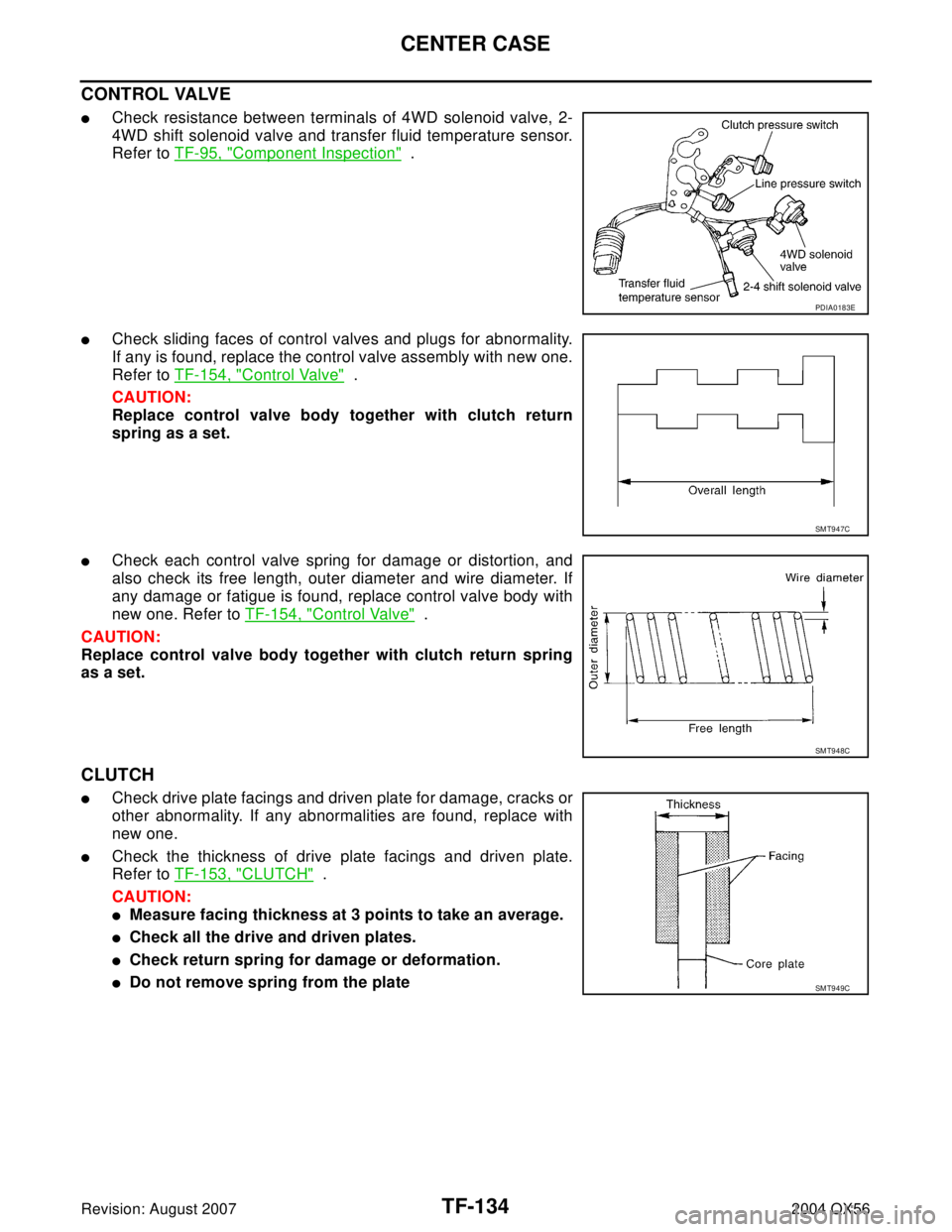
�Check resistance between terminals of 4WD solenoid valve, 2-
4WD shift solenoid valve and transfer fluid temperature sensor.
Refer to TF-95, "
Component Inspection" .
�Check sliding faces of control valves and plugs for abnormality.
If any is found, replace the control valve assembly with new one.
Refer to TF-154, "
Control Valve" .
CAUTION:
Replace control valve body together with clutch return
spring as a set.
�Check each control valve spring for damage or distortion, and
also check its free length, outer diameter and wire diameter. If
any damage or fatigue is found, replace control valve body with
new one. Refer to TF-154, "
Control Valve" .
CAUTION:
Replace control valve body together with clutch return spring
as a set.
CLUTCH
�Check drive plate facings and driven plate for damage, cracks or
other abnormality. If any abnormalities are found, replace with
new one.
�Check the thickness of drive plate facings and driven plate.
Refer to TF-153, "
CLUTCH" .
CAUTION:
�Measure facing thickness at 3 points to take an average.
�Check all the drive and driven plates.
�Check return spring for damage or deformation.
�Do not remove spring from the plate
PDIA0183E
SMT947C
SMT948C
SMT949C
Page 3268 of 3371

CENTER CASE
TF-143
C
E
F
G
H
I
J
K
L
MA
B
TF
Revision: August 20072004 QX56
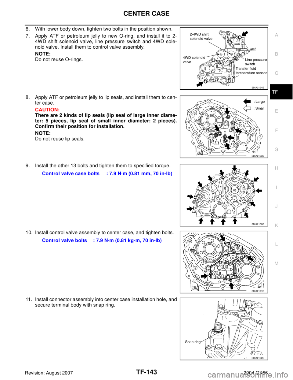
6. With lower body down, tighten two bolts in the position shown.
7. Apply ATF or petroleum jelly to new O-ring, and install it to 2-
4WD shift solenoid valve, line pressure switch and 4WD sole-
noid valve. Install them to control valve assembly.
NOTE:
Do not reuse O-rings.
8. Apply ATF or petroleum jelly to lip seals, and install them to cen-
ter case.
CAUTION:
There are 2 kinds of lip seals (lip seal of large inner diame-
ter: 5 pieces, lip seal of small inner diameter: 2 pieces).
Confirm their position for installation.
NOTE:
Do not reuse lip seals.
9. Install the other 13 bolts and tighten them to specified torque.
10. Install control valve assembly to center case, and tighten bolts.
11. Install connector assembly into center case installation hole, and
secure terminal body with snap ring.
SDIA2124E
SDIA2123E
Control valve case bolts : 7.9 N·m (0.81 mm, 70 in-lb)
SDIA2100E
Control valve bolts : 7.9 N·m (0.81 kg-m, 70 in-lb)
SDIA2121E
SDIA2122E