Page 2092 of 3371

HOW TO USE THIS MANUAL
GI-11
C
D
E
F
G
H
I
J
K
L
MB
GI
Revision: August 20072004 QX56
How to Follow Trouble DiagnosesEAS0014K
DESCRIPTION
NOTICE:
Trouble diagnoses indicate work procedures required to diagnose problems effectively. Observe the following
instructions before diagnosing.
1.Before performing trouble diagnoses, read the “Preliminary Check”, the “Symptom Chart” or the
“Work Flow”.
2.After repairs, re-check that the problem has been completely eliminated.
3.Refer to Component Parts and Harness Connector Location for the Systems described in each
section for identification/location of components and harness connectors.
4.Refer to the Circuit Diagram for quick pinpoint check.
If you need to check circuit continuity between harness connectors in more detail, such as when a
sub-harness is used, refer to Wiring Diagram in each individual section and Harness Layout in PG
section for identification of harness connectors.
5.When checking circuit continuity, ignition switch should be OFF.
6.Before checking voltage at connectors, check battery voltage.
7.After accomplishing the Diagnostic Procedures and Electrical Components Inspection, make sure
that all harness connectors are reconnected as they were.
HOW TO FOLLOW TEST GROUPS IN TROUBLE DIAGNOSES
1.Work and diagnostic procedure
Start to diagnose a problem using procedures indicated in enclosed test groups.
2.Questions and required results
Questions and required results are indicated in bold type in test group.
The meaning of are as follows:
SAIA0256E
Page 2096 of 3371
HOW TO USE THIS MANUAL
GI-15
C
D
E
F
G
H
I
J
K
L
MB
GI
Revision: August 20072004 QX56
How to Read Wiring DiagramsEAS0014L
CONNECTOR SYMBOLS
Most of connector symbols in wiring diagrams are shown from the
terminal side.
�Connector symbols shown from the terminal side are enclosed
by a single line and followed by the direction mark.
�Connector symbols shown from the harness side are enclosed
by a double line and followed by the direction mark.
�Certain systems and components, especially related to OBD,
may use a new style slide-locking type harness connector. For
description and how to disconnect, refer to PG-68, "
HARNESS
CONNECTOR" .
�Male and female terminals
Connector guides for male terminals are shown in black and
female terminals in white in wiring diagrams.
SGI364
SGI363
Page 2097 of 3371
GI-16
HOW TO USE THIS MANUAL
Revision: August 20072004 QX56
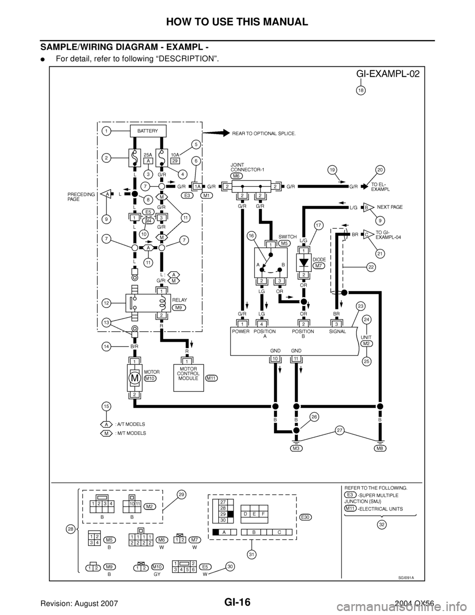
SAMPLE/WIRING DIAGRAM - EXAMPL -
�For detail, refer to following “DESCRIPTION”.
SG I0 91 A
Page 2099 of 3371

GI-18
HOW TO USE THIS MANUAL
Revision: August 20072004 QX56
14 Wire color
�This shows a code for the color of the wire.
B = Black
W = White
R = Red
G = Green
L = Blue
Y = Yellow
LG = Light GreenBR = Brown
OR or O = Orange
P = Pink
PU or V (Violet) = Purple
GY or GR = Gray
SB = Sky Blue
CH = Dark Brown
DG = Dark Green
When the wire color is striped, the base color is given first, followed by the stripe color as shown
below:
Example: L/W = Blue with White Stripe
15 Option description
�This shows a description of the option abbreviation used on the page.
16 Switch
�This shows that continuity exists between terminals 1 and 2 when the switch is in the A posi-
tion. Continuity exists between terminals 1 and 3 when the switch is in the B position.
17 Assembly parts
�Connector terminal in component shows that it is a harness incorporated assembly.
18 Cell code
�This identifies each page of the wiring diagram by section, system and wiring diagram page
number.
19 Current flow arrow
�Arrow indicates electric current flow, especially where the direction of standard flow (vertically
downward or horizontally from left to right) is difficult to follow.
�A double arrow “ ” shows that current can flow in either direction depending on cir-
cuit operation.
20 System branch
�This shows that the system branches to another system identified by cell code (section and
system).
21 Page crossing
�This arrow shows that the circuit continues to another page identified by cell code.
�The C will match with the C on another page within the system other than the next or preced-
ing pages.
22 Shielded line
�The line enclosed by broken line circle shows shield wire.
23Component box in
wave line
�This shows that another part of the component is also shown on another page (indicated by
wave line) within the system.
24 Component name
�This shows the name of a component.
25 Connector number
�This shows the connector number.
�The letter shows which harness the connector is located in.
�Example: M : main harness. For detail and to locate the connector, refer to PG section "Main
Harness", “Harness Layout”. A coordinate grid is included for complex harnesses to aid in
locating connectors.
26 Ground (GND)
�The line spliced and grounded under wire color shows that ground line is spliced at the
grounded connector.
27 Ground (GND)
�This shows the ground connection. For detailed ground distribution information, refer to
"Ground Distribution" in PG section.
28 Connector views
�This area shows the connector faces of the components in the wiring diagram on the page.
29 Common component
�Connectors enclosed in broken line show that these connectors belong to the same compo-
nent.
30 Connector color
�This shows a code for the color of the connector. For code meaning, refer to wire color codes,
Number 14 of this chart.
31Fusible link and fuse
box
�This shows the arrangement of fusible link(s) and fuse(s), used for connector views of
"POWER SUPPLY ROUTING" in PG section.
The open square shows current flow in, and the shaded square shows current flow out.
32 Reference area
�This shows that more information on the Super Multiple Junction (SMJ) and Joint Connectors
(J/C) exists on the PG section. Refer to "Reference Area" for details. Num-
berItem Description
Page 2100 of 3371
HOW TO USE THIS MANUAL
GI-19
C
D
E
F
G
H
I
J
K
L
MB
GI
Revision: August 20072004 QX56
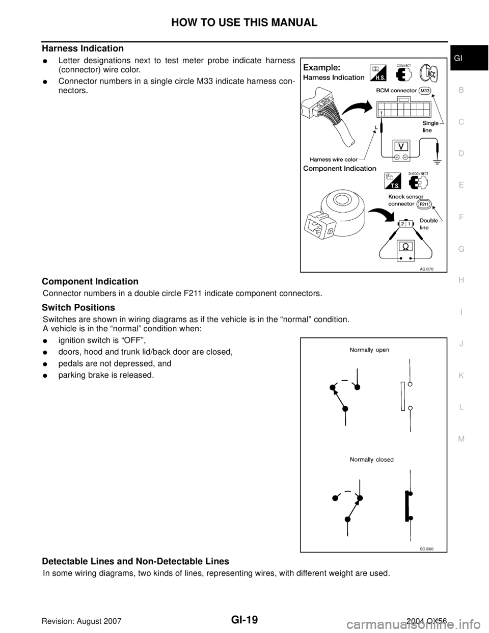
Harness Indication
�Letter designations next to test meter probe indicate harness
(connector) wire color.
�Connector numbers in a single circle M33 indicate harness con-
nectors.
Component Indication
Connector numbers in a double circle F211 indicate component connectors.
Switch Positions
Switches are shown in wiring diagrams as if the vehicle is in the “normal” condition.
A vehicle is in the “normal” condition when:
�ignition switch is “OFF”,
�doors, hood and trunk lid/back door are closed,
�pedals are not depressed, and
�parking brake is released.
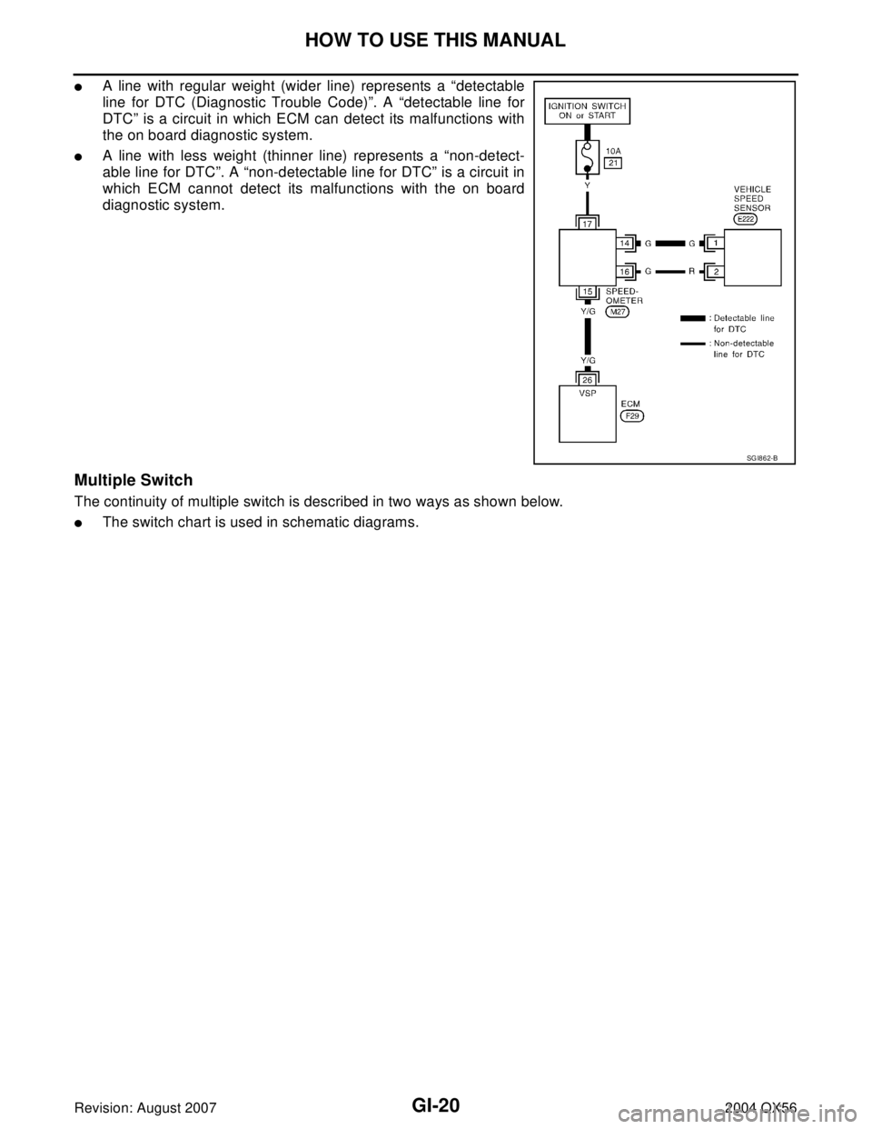
Detectable Lines and Non-Detectable Lines
In some wiring diagrams, two kinds of lines, representing wires, with different weight are used.
AGI070
SGI860
Page 2101 of 3371
GI-20
HOW TO USE THIS MANUAL
Revision: August 20072004 QX56
�A line with regular weight (wider line) represents a “detectable
line for DTC (Diagnostic Trouble Code)”. A “detectable line for
DTC” is a circuit in which ECM can detect its malfunctions with
the on board diagnostic system.
�A line with less weight (thinner line) represents a “non-detect-
able line for DTC”. A “non-detectable line for DTC” is a circuit in
which ECM cannot detect its malfunctions with the on board
diagnostic system.
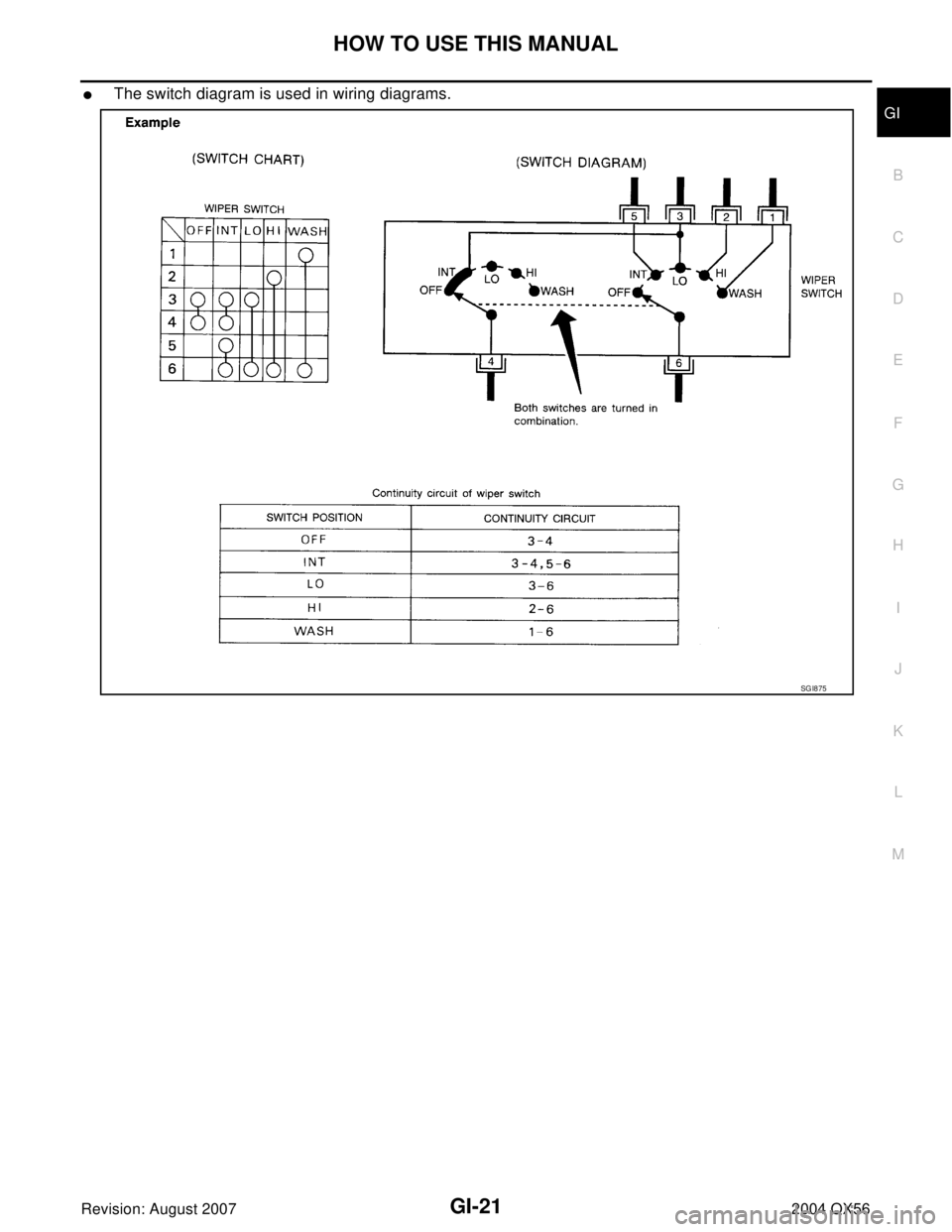
Multiple Switch
The continuity of multiple switch is described in two ways as shown below.
�The switch chart is used in schematic diagrams.
SGI862-B
Page 2102 of 3371
HOW TO USE THIS MANUAL
GI-21
C
D
E
F
G
H
I
J
K
L
MB
GI
Revision: August 20072004 QX56
�The switch diagram is used in wiring diagrams.
SG I8 75
Page 2103 of 3371
GI-22
HOW TO USE THIS MANUAL
Revision: August 20072004 QX56
Reference Area
The Reference Area of the wiring diagram contains references to additional electrical reference pages at the
end of the manual. If connector numbers and titles are shown in the Reference Area of the wiring diagram,
these connector symbols are not shown in the Connector Area.
AbbreviationsEAS0014M
The following ABBREVIATIONS are used:
SG I0 92 A
ABBREVIATION DESCRIPTION
A/C Air Conditioner
A/T Automatic Transaxle/Transmission
ATF Automatic Transmission Fluid
D
1Drive range 1st gear
D
2Drive range 2nd gear