Page 1805 of 3371
EC-614Revision: August 2007
ICC BRAKE SWITCH
2004 QX56
Wiring DiagramUBS00HZC
BBWA1786E
Page 1810 of 3371

ICC BRAKE SWITCH
EC-619
C
D
E
F
G
H
I
J
K
L
MA
EC
Revision: August 20072004 QX56
11 . DETECT MALFUNCTIONING PART
Check the following.
�Harness connectors M31, E152
�Fuse block (J/B) connector M60
�10A fuse
�Harness for open or short between stop lamp switch and battery
>> Repair open circuit or short to ground or short to power in harness or connectors.
12. CHECK STOP LAMP SWITCH INPUT SIGNAL CIRCUIT FOR OPEN AND SHORT
1. Disconnect ECM harness connector.
2. Check harness continuity between ECM terminal 101 and stop lamp switch terminal 4.
Refer to Wiring Diagram.
3. Also check harness for short to ground and short to power.
OK or NG
OK >> GO TO 13.
NG >> Repair open circuit or short to ground or short to power in harness or connectors.
13. CHECK STOP LAMP SWITCH
Refer to EC-532, "
Component Inspection"
OK or NG
OK >> GO TO 14.
NG >> Replace stop lamp switch.
14. CHECK INTERMITTENT INCIDENT
Refer to EC-127, "
TROUBLE DIAGNOSIS FOR INTERMITTENT INCIDENT" .
>>INSPECTION END
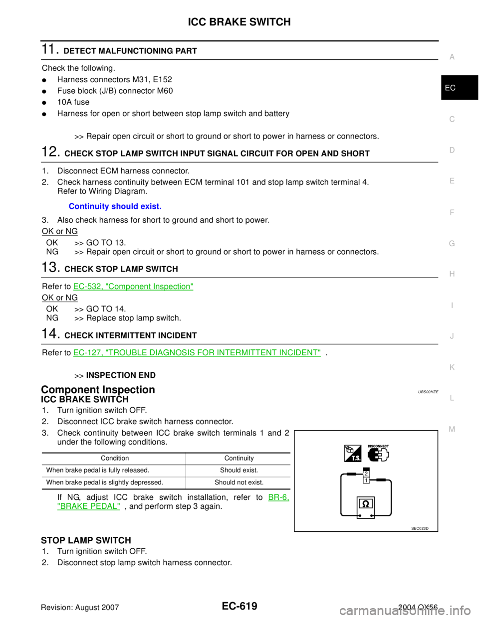
Component InspectionUBS00HZE
ICC BRAKE SWITCH
1. Turn ignition switch OFF.
2. Disconnect ICC brake switch harness connector.
3. Check continuity between ICC brake switch terminals 1 and 2
under the following conditions.
If NG, adjust ICC brake switch installation, refer to BR-6,
"BRAKE PEDAL" , and perform step 3 again.
STOP LAMP SWITCH
1. Turn ignition switch OFF.
2. Disconnect stop lamp switch harness connector.Continuity should exist.
Condition Continuity
When brake pedal is fully released. Should exist.
When brake pedal is slightly depressed. Should not exist.
SEC0 23 D
Page 1813 of 3371
EC-622Revision: August 2007
ASCD BRAKE SWITCH
2004 QX56
Wiring DiagramUBS00HDQ
BBWA11 93 E
Page 1816 of 3371

ASCD BRAKE SWITCH
EC-625
C
D
E
F
G
H
I
J
K
L
MA
EC
Revision: August 20072004 QX56
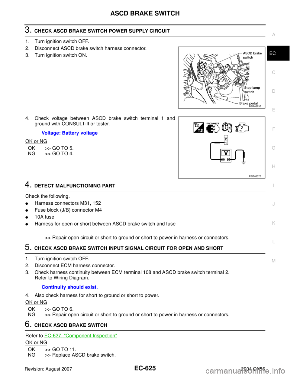
3. CHECK ASCD BRAKE SWITCH POWER SUPPLY CIRCUIT
1. Turn ignition switch OFF.
2. Disconnect ASCD brake switch harness connector.
3. Turn ignition switch ON.
4. Check voltage between ASCD brake switch terminal 1 and
ground with CONSULT-II or tester.
OK or NG
OK >> GO TO 5.
NG >> GO TO 4.
4. DETECT MALFUNCTIONING PART
Check the following.
�Harness connectors M31, 152
�Fuse block (J/B) connector M4
�10A fuse
�Harness for open or short between ASCD brake switch and fuse
>> Repair open circuit or short to ground or short to power in harness or connectors.
5. CHECK ASCD BRAKE SWITCH INPUT SIGNAL CIRCUIT FOR OPEN AND SHORT
1. Turn ignition switch OFF.
2. Disconnect ECM harness connector.
3. Check harness continuity between ECM terminal 108 and ASCD brake switch terminal 2.
Refer to Wiring Diagram.
4. Also check harness for short to ground or short to power.
OK or NG
OK >> GO TO 6.
NG >> Repair open circuit or short to ground or short to power in harness or connectors.
6. CHECK ASCD BRAKE SWITCH
Refer to EC-627, "
Component Inspection"
OK or NG
OK >> GO TO 11.
NG >> Replace ASCD brake switch.
BBIA0373E
Voltage: Battery voltage
PBIB0857E
Continuity should exist.
Page 1817 of 3371

EC-626Revision: August 2007
ASCD BRAKE SWITCH
2004 QX56
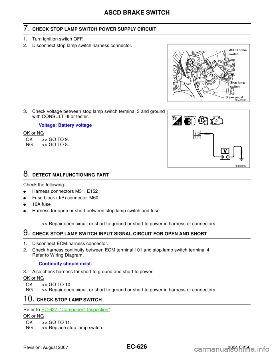
7. CHECK STOP LAMP SWITCH POWER SUPPLY CIRCUIT
1. Turn ignition switch OFF.
2. Disconnect stop lamp switch harness connector.
3. Check voltage between stop lamp switch terminal 3 and ground
with CONSULT -II or tester.
OK or NG
OK >> GO TO 9.
NG >> GO TO 8.
8. DETECT MALFUNCTIONING PART
Check the following.
�Harness connectors M31, E152
�Fuse block (J/B) connector M60
�10A fuse
�Harness for open or short between stop lamp switch and fuse
>> Repair open circuit or short to ground or short to power in harness or connectors.
9. CHECK STOP LAMP SWITCH INPUT SIGNAL CIRCUIT FOR OPEN AND SHORT
1. Disconnect ECM harness connector.
2. Check harness continuity between ECM terminal 101 and stop lamp switch terminal 4.
Refer to Wiring Diagram.
3. Also check harness for short to ground and short to power.
OK or NG
OK >> GO TO 10.
NG >> Repair open circuit or short to ground or short to power in harness or connectors.
10. CHECK STOP LAMP SWITCH
Refer to EC-627, "
Component Inspection"
OK or NG
OK >> GO TO 11.
NG >> Replace stop lamp switch.
BBIA0373E
Voltage: Battery voltage
PBIB2309E
Continuity should exist.
Page 1820 of 3371
ASCD INDICATOR
EC-629
C
D
E
F
G
H
I
J
K
L
MA
EC
Revision: August 20072004 QX56
Wiring DiagramUBS00HDV
BBWA1996E
Page 1822 of 3371
MIL AND DATA LINK CONNECTOR
EC-631
C
D
E
F
G
H
I
J
K
L
MA
EC
Revision: August 20072004 QX56
MIL AND DATA LINK CONNECTORPFP:24814
Wiring DiagramUBS00HDX
BBWA1997E
Page 2082 of 3371

GI-1
GENERAL INFORMATION
A GENERAL INFORMATION
CONTENTS
C
D
E
F
G
H
I
J
K
L
MB
GI
SECTION GI
Revision: August 20072004 QX56 PRECAUTIONS .......................................................... 3
Description ............................................................... 3
Precautions for Supplemental Restraint System
(SRS) “AIR BAG” and “SEAT BELT PRE-TEN-
SIONER” .................................................................. 3
Precautions for NVIS/IVIS (NISSAN/INFINITI
VEHICLE IMMOBILIZER SYSTEM - NATS) (If
Equipped) ................................................................. 3
General Precautions ................................................ 4
Precautions for Three Way Catalyst ......................... 5
Precautions for Fuel (Unleaded Premium Gasoline
Required) ................................................................. 5
Precautions for Multiport Fuel Injection System or
Engine Control System ............................................ 6
Precautions for Hoses .............................................. 6
HOSE REMOVAL AND INSTALLATION ............... 6
HOSE CLAMPING ................................................ 6
Precautions for Engine Oils ...................................... 7
HEALTH PROTECTION PRECAUTIONS ............. 7
Precautions for Air Conditioning ............................... 7
HOW TO USE THIS MANUAL ................................... 8
Description ............................................................... 8
Terms ....................................................................... 8
Units ......................................................................... 8
Contents ................................................................... 8
Relation between Illustrations and Descriptions ...... 9
Components ........................................................... 10
SYMBOLS ........................................................... 10
How to Follow Trouble Diagnoses ...........................11
DESCRIPTION .....................................................11
HOW TO FOLLOW TEST GROUPS IN TROU-
BLE DIAGNOSES ................................................11
HARNESS WIRE COLOR AND CONNECTOR
NUMBER INDICATION ....................................... 12
KEY TO SYMBOLS SIGNIFYING MEASURE-
MENTS OR PROCEDURES ............................... 13
How to Read Wiring Diagrams ............................... 15
CONNECTOR SYMBOLS ................................... 15
SAMPLE/WIRING DIAGRAM - EXAMPL - ......... 16DESCRIPTION .................................................... 17
Abbreviations .......................................................... 22
SERVICE INFORMATION FOR ELECTRICAL INCI-
DENT ......................................................................... 24
How to Check Terminal ........................................... 24
CONNECTOR AND TERMINAL PIN KIT ............ 24
HOW TO PROBE CONNECTORS ...................... 24
How to Perform Efficient Diagnosis for an Electrical
Incident ................................................................... 27
WORK FLOW ...................................................... 27
INCIDENT SIMULATION TESTS ........................ 27
CIRCUIT INSPECTION ....................................... 30
Control Units and Electrical Parts ........................... 35
PRECAUTIONS .................................................. 35
SMJ INSTALLATION ........................................... 36
CONSULT-II CHECKING SYSTEM .......................... 37
Description .............................................................. 37
Function and System Application ........................... 37
Nickel Metal Hydride Battery Replacement ............ 38
Checking Equipment .............................................. 38
CONSULT-II Start Procedure .................................. 38
CONSULT-II Data Link Connector (DLC) Circuit .... 39
INSPECTION PROCEDURE .............................. 39
LIFTING POINT ......................................................... 40
Pantograph Jack ..................................................... 40
Garage Jack and Safety Stand ............................... 40
2-Pole Lift ............................................................... 41
TOW TRUCK TOWING ............................................. 42
Tow Truck Towing ................................................... 42
2WD MODELS .................................................... 42
4WD MODELS .................................................... 43
Vehicle Recovery (Freeing a stuck vehicle) ............ 43
TIGHTENING TORQUE OF STANDARD BOLTS .... 44
Tightening Torque Table ......................................... 44
RECOMMENDED CHEMICAL PRODUCTS AND
SEALANTS ............................................................... 45
Recommended Chemical Products and Sealants ... 45
IDENTIFICATION INFORMATION ............................ 46
Model Variation ....................................................... 46
Identification Number .............................................. 47