2004 INFINITI QX56 wheel
[x] Cancel search: wheelPage 3141 of 3371

TF-16
ALL-MODE 4WD SYSTEM
Revision: August 20072004 QX56
LINE PRESSURE SWITCH
1. With the transfer system design, control of the oil pressure provides the transmission of drive torque to the
front wheels. The main pressure to control the oil pressure is referred to as the line pressure.
The line pressure switch determines whether or not adequate line pressure has built up under different
operating conditions.
2. The line pressure switch turns ON when line pressure is produced.
3. The line pressure switch senses line pressure abnormalities and turns the 4WD warning lamp ON.
Page 3154 of 3371
ON BOARD DIAGNOSTIC SYSTEM DESCRIPTION
TF-29
C
E
F
G
H
I
J
K
L
MA
B
TF
Revision: August 20072004 QX56
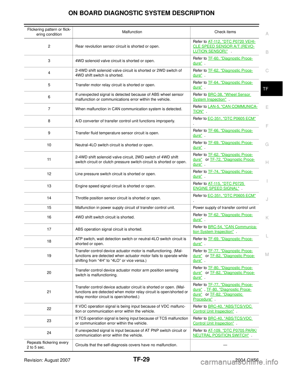
Flickering pattern or flick-
ering conditionMalfunction Check items
2 Rear revolution sensor circuit is shorted or open.Refer to AT- 11 2 , "
DTC P0720 VEHI-
CLE SPEED SENSOR A/T (REVO-
LUTION SENSOR)" .
3 4WD solenoid valve circuit is shorted or open.Refer to TF-60, "
Diagnostic Proce-
dure" .
42-4WD shift solenoid valve circuit is shorted or 2WD switch of
4WD shift switch is shorted.Refer to TF-62, "
Diagnostic Proce-
dure" .
5 Transfer motor relay circuit is shorted or open.Refer to TF-64, "
Diagnostic Proce-
dure" .
6If unexpected signal is detected because of ABS wheel sensor
malfunction or communications error within the vehicle.Refer to BRC-38, "
Wheel Sensor
System Inspection" .
7 When malfunction in CAN communication system is detected.Refer to LAN-5, "
CAN COMMUNICA-
TION" .
8 A/D converter of transfer control unit functions improperly.Refer to EC-351, "
DTC P0605 ECM"
.
9 Transfer fluid temperature sensor circuit is open.Refer to TF-66, "
Diagnostic Proce-
dure" .
10 Neutral-4LO switch circuit is shorted or open.Refer to TF-69, "
Diagnostic Proce-
dure" .
112-4WD shift solenoid valve circuit, 2WD switch of 4WD shift
switch circuit or clutch pressure switch circuit is shorted or open.Refer to TF-62, "
Diagnostic Proce-
dure" or TF-72, "Diagnostic Proce-
dure" .
12 Line pressure switch circuit is shorted or open.Refer to TF-74, "
Diagnostic Proce-
dure" .
13 Engine speed signal circuit is shorted or open.Refer to AT- 11 5 , "
DTC P0725
ENGINE SPEED SIGNAL" .
14 Throttle position sensor circuit is shorted or open.Refer to EC-351, "
DTC P0605 ECM"
.
15 Malfunction in power supply circuit of transfer control unit. Power supply of transfer control unit
16 4WD shift switch circuit is shorted.Refer to TF-62, "
Diagnostic Proce-
dure" .
17 ABS operation signal circuit is shorted.Refer to BRC-54, "
CAN Communica-
tion System Inspection" .
18ATP switch, wait detection switch or neutral-4LO switch circuit is
shorted or open.Refer to TF-69, "
Diagnostic Proce-
dure" .
19Transfer control device actuator motor is malfunctioning. (Mal-
functions are detected when actuator motor fails to operate while
shifting from “4H” to “4LO” or vice versa.)Refer to TF-77, "
Diagnostic Proce-
dure" or TF-82, "Diagnostic Proce-
dure" .
20Transfer control device actuator motor arm position sensing
switch is malfunctioning.Refer to TF-80, "
Diagnostic Proce-
dure" or TF-82, "Diagnostic Proce-
dure" .
21Transfer control device actuator circuit is shorted or open. (Mal-
functions are detected when motor relay circuit is open/shorted or
relay monitor circuit is open/shorted.)Refer to TF-77, "
Diagnostic Proce-
dure" , TF-80, "Diagnostic Proce-
dure" or TF-82, "Diagnostic
Procedure" .
22If VDC operation signal is being input because of VDC malfunc-
tion or communication error within the vehicle.Refer to BRC-40, "
ABS/TCS/VDC
Control Unit Inspection" .
23If TCS operation signal is being input because of TCS malfunction
or communication error within the vehicle.Refer to BRC-40, "
ABS/TCS/VDC
Control Unit Inspection" .
24If unexpected signal is input because of AT PNP switch circuit or
communication error within the vehicle.Refer to AT- 1 0 9 , "
DTC P0705 PARK/
NEUTRAL POSITION SWITCH" .
Repeats flickering every
2 to 5 sec.Circuits that the self-diagnosis covers have no malfunction. —
Page 3160 of 3371
ON BOARD DIAGNOSTIC SYSTEM DESCRIPTION
TF-35
C
E
F
G
H
I
J
K
L
MA
B
TF
Revision: August 20072004 QX56
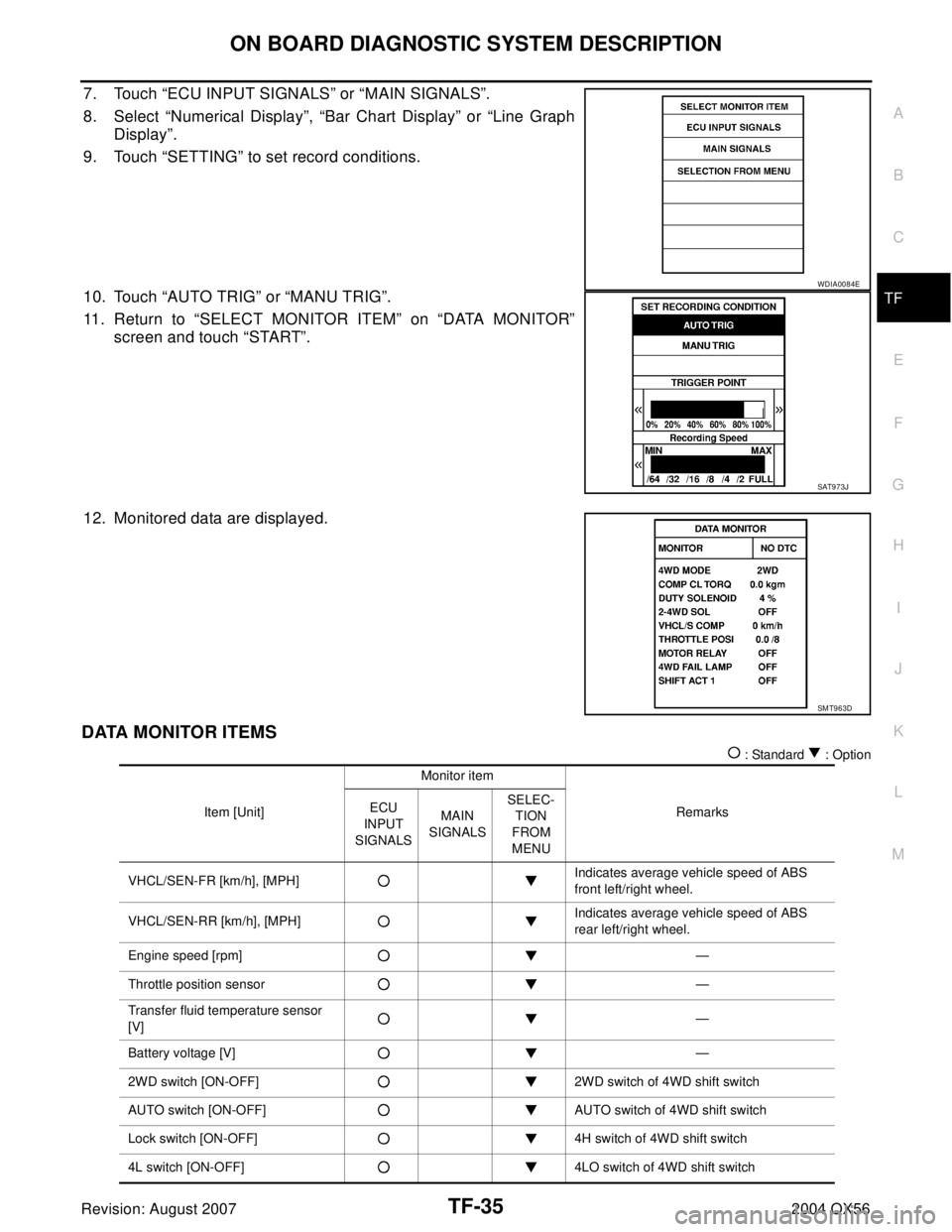
7. Touch “ECU INPUT SIGNALS” or “MAIN SIGNALS”.
8. Select “Numerical Display”, “Bar Chart Display” or “Line Graph
Display”.
9. Touch “SETTING” to set record conditions.
10. Touch “AUTO TRIG” or “MANU TRIG”.
11. Return to “SELECT MONITOR ITEM” on “DATA MONITOR”
screen and touch “START”.
12. Monitored data are displayed.
DATA MONITOR ITEMS
: Standard : Option
WDIA0084E
SAT9 7 3J
SMT963D
Item [Unit]Monitor item
Remarks ECU
INPUT
SIGNALSMAIN
SIGNALSSELEC-
TION
FROM
MENU
VHCL/SEN-FR [km/h], [MPH]Indicates average vehicle speed of ABS
front left/right wheel.
VHCL/SEN-RR [km/h], [MPH]Indicates average vehicle speed of ABS
rear left/right wheel.
Engine speed [rpm]—
Throttle position sensor—
Transfer fluid temperature sensor
[V]—
Battery voltage [V]—
2WD switch [ON-OFF] 2WD switch of 4WD shift switch
AUTO switch [ON-OFF] AUTO switch of 4WD shift switch
Lock switch [ON-OFF] 4H switch of 4WD shift switch
4L switch [ON-OFF] 4LO switch of 4WD shift switch
Page 3165 of 3371

TF-40
ON BOARD DIAGNOSTIC SYSTEM DESCRIPTION
Revision: August 20072004 QX56
4WD-mode2WD
4WD shift
switchIn “2WD” position
AUTO In “AUTO” position
LOCK In “4H” position
4L In “4LO” position
Front wheel speed
(VHCL/S SEN-FR)0 - 255 km/h (0 - 158 MPH) 0 km/h (vehicle at standstill)
Rear wheel speed
(VHCL/S SEN-RR)0 - 255 km/h (0 - 158 MPH) 0 km/h (vehicle at standstill)
Shift ACTR operating 1
(SHIFT ACT 1)
Shift activating monitor 1
(SHIFT AC MON 1)OFF During normal operation
ON During shifts from “4H” to “4LO” position
Shift ACTR operating 2
(SHIFT ACT 2)
Shift activating monitor 2
(SHIFT AC MON 2)OFF During normal operation
ON During shifts from “4LO” to “4H” position
4WD fail lampOFF During normal operation
ONDuring 2-second period (after key switch turned to “ON”)
or when system is out of order
Shift ACTR position sensing switch 1
(SHIFT POS SW 1)OFF 4WD shift switch is in a position other than “4LO”.
ON 4WD shift switch in “4LO” position
Shift ACTR position sensing switch 2
(SHIFT POS SW 2)OFF 4WD shift switch in “4LO” position
ON 4WD shift switch is in a position other than “4LO”.
2WD indicator lamp
(2WD IND)OFF Engine at rest or system out of order
ON Except the above condition Indicated items
(Screen terms for CONSULT-II, “DATA
MONITOR” mode)Display Conditions
Page 3179 of 3371
TF-54
TROUBLE DIAGNOSIS — BASIC INSPECTION
Revision: August 20072004 QX56
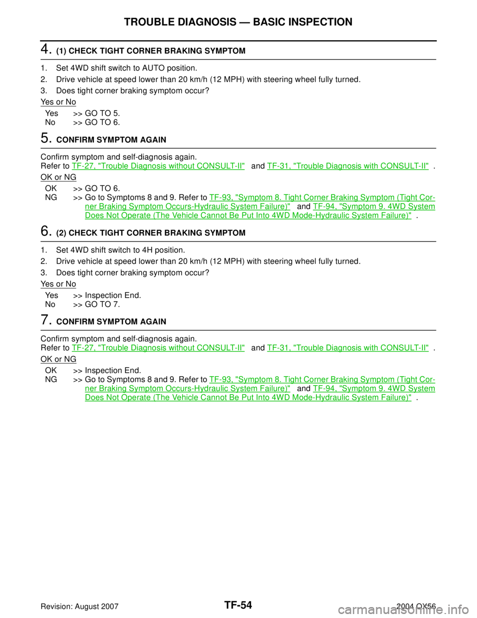
4. (1) CHECK TIGHT CORNER BRAKING SYMPTOM
1. Set 4WD shift switch to AUTO position.
2. Drive vehicle at speed lower than 20 km/h (12 MPH) with steering wheel fully turned.
3. Does tight corner braking symptom occur?
Ye s o r N o
Yes >> GO TO 5.
No >> GO TO 6.
5. CONFIRM SYMPTOM AGAIN
Confirm symptom and self-diagnosis again.
Refer to TF-27, "
Trouble Diagnosis without CONSULT-II" and TF-31, "Trouble Diagnosis with CONSULT-II" .
OK or NG
OK >> GO TO 6.
NG >> Go to Symptoms 8 and 9. Refer to TF-93, "
Symptom 8. Tight Corner Braking Symptom (Tight Cor-
ner Braking Symptom Occurs-Hydraulic System Failure)" and TF-94, "Symptom 9. 4WD System
Does Not Operate (The Vehicle Cannot Be Put Into 4WD Mode-Hydraulic System Failure)" .
6. (2) CHECK TIGHT CORNER BRAKING SYMPTOM
1. Set 4WD shift switch to 4H position.
2. Drive vehicle at speed lower than 20 km/h (12 MPH) with steering wheel fully turned.
3. Does tight corner braking symptom occur?
Ye s o r N o
Yes >> Inspection End.
No >> GO TO 7.
7. CONFIRM SYMPTOM AGAIN
Confirm symptom and self-diagnosis again.
Refer to TF-27, "
Trouble Diagnosis without CONSULT-II" and TF-31, "Trouble Diagnosis with CONSULT-II" .
OK or NG
OK >> Inspection End.
NG >> Go to Symptoms 8 and 9. Refer to TF-93, "
Symptom 8. Tight Corner Braking Symptom (Tight Cor-
ner Braking Symptom Occurs-Hydraulic System Failure)" and TF-94, "Symptom 9. 4WD System
Does Not Operate (The Vehicle Cannot Be Put Into 4WD Mode-Hydraulic System Failure)" .
Page 3217 of 3371
TF-92
TROUBLE DIAGNOSES FOR SYMPTOMS
Revision: August 20072004 QX56
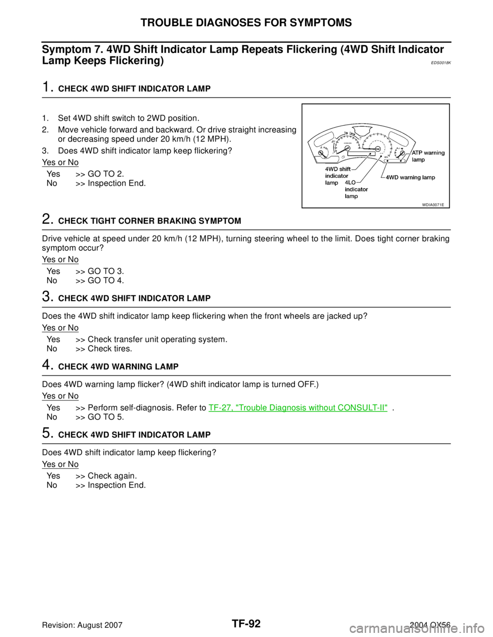
Symptom 7. 4WD Shift Indicator Lamp Repeats Flickering (4WD Shift Indicator
Lamp Keeps Flickering)
EDS0018K
1. CHECK 4WD SHIFT INDICATOR LAMP
1. Set 4WD shift switch to 2WD position.
2. Move vehicle forward and backward. Or drive straight increasing
or decreasing speed under 20 km/h (12 MPH).
3. Does 4WD shift indicator lamp keep flickering?
Ye s o r N o
Yes >> GO TO 2.
No >> Inspection End.
2. CHECK TIGHT CORNER BRAKING SYMPTOM
Drive vehicle at speed under 20 km/h (12 MPH), turning steering wheel to the limit. Does tight corner braking
symptom occur?
Ye s o r N o
Yes >> GO TO 3.
No >> GO TO 4.
3. CHECK 4WD SHIFT INDICATOR LAMP
Does the 4WD shift indicator lamp keep flickering when the front wheels are jacked up?
Ye s o r N o
Yes >> Check transfer unit operating system.
No >> Check tires.
4. CHECK 4WD WARNING LAMP
Does 4WD warning lamp flicker? (4WD shift indicator lamp is turned OFF.)
Ye s o r N o
Yes >> Perform self-diagnosis. Refer to TF-27, "Trouble Diagnosis without CONSULT-II" .
No >> GO TO 5.
5. CHECK 4WD SHIFT INDICATOR LAMP
Does 4WD shift indicator lamp keep flickering?
Ye s o r N o
Yes >> Check again.
No >> Inspection End.
WDIA0071E
Page 3280 of 3371

WT-1
ROAD WHEELS & TIRES
E SUSPENSION
CONTENTS
C
D
F
G
H
I
J
K
L
M
SECTION WT
A
B
WT
Revision: August 20072004 QX56 PREPARATION ........................................................... 2
Special Service Tool ................................................. 2
Commercial Service Tools ........................................ 2
NOISE, VIBRATION, AND HARSHNESS (NVH)
TROUBLESHOOTING ................................................ 3
NVH Troubleshooting Chart ..................................... 3
WHEEL ....................................................................... 4
Inspection ................................................................. 4
WHEEL AND TIRE ASSEMBLY ................................. 5
Balancing Wheels .................................................... 5
REMOVAL ............................................................. 5
WHEEL BALANCE ADJUSTMENT ...................... 5
Rotation .................................................................... 6
LOW TIRE PRESSURE WARNING SYSTEM ............ 7
System Components ................................................ 7
System Description .................................................. 7
TRANSMITTER ..................................................... 7
REMOTE KEYLESS ENTRY RECEIVER ............. 7
BCM (BODY CONTROL MODULE) ...................... 8
LOW TIRE PRESSURE WARNING LAMP AND
BUZZER ................................................................ 8
DISPLAY UNIT ...................................................... 8
CAN COMMUNICATION ............................................ 9
System Description .................................................. 9
TROUBLE DIAGNOSES .......................................... 10
Wiring Diagram — T/WARN — .............................. 10
Terminal and Reference Value (BCM) .................... 12
ID Registration Procedure ...................................... 13
ID REGISTRATION WITH TRANSMITTER
ACTIVATION TOOL ............................................ 13
ID REGISTRATION WITHOUT TRANSMITTER
ACTIVATION TOOL ............................................ 14
Transmitter Wake Up Operation ............................. 15
............................................................................ 15
CONSULT-II Function (BCM) ................................. 16
Self-Diagnosis ........................................................ 17
DESCRIPTION .................................................... 17
FUNCTION .......................................................... 17CONSULT-II ......................................................... 17
How to Perform Trouble Diagnosis for Quick and
Accurate Repair ...................................................... 19
INTRODUCTION ................................................. 19
WORK FLOW ...................................................... 19
Preliminary Check .................................................. 20
Malfunction Code/Symptom Chart .......................... 21
TROUBLE DIAGNOSIS FOR SELF-DIAGNOSTIC
ITEMS ........................................................................ 23
Inspection 1: Transmitter or Control Unit (BCM) ..... 23
MALFUNCTION CODE NO. 21, 22, 23 OR 24 ... 23
Inspection 2: Transmitter - 1 ................................... 23
MALFUNCTION CODE NO. 31, 32, 33, 34, 41,
42, 43, 44, 45, 46, 47 OR 48 ............................... 23
Inspection 3: Transmitter - 2 ................................... 24
MALFUNCTION CODE NO. 35, 36, 37 OR 38 ... 24
Inspection 4: Vehicle Speed Signal ........................ 25
MALFUNCTION CODE NO. 52 ........................... 25
TROUBLE DIAGNOSIS FOR SYMPTOMS .............. 26
Inspection 1: Low Tire Pressure Warning Lamp
Does Not Come On When Ignition Switch Is Turned
On ........................................................................... 26
Inspection 2: Low Tire Pressure Warning Lamp
Stays On When Ignition Switch Is Turned On ......... 26
Inspection 3: Low Tire Pressure Warning Lamp
Flashes When Ignition Switch Is Turned On .......... 28
Inspection 4: Hazard Warning Lamp Flashes When
Ignition Switch Is Turned On .................................. 29
Inspection 5: “TIRE PRESSURE” Information In
Display Unit Does Not Exist .................................... 30
Inspection 6: ID Registration Cannot Be Completed ... 30
REMOVAL AND INSTALLATION ............................. 31
Transmitter (Pressure Sensor) ............................... 31
REMOVAL ........................................................... 31
INSTALLATION ................................................... 31
SERVICE DATA AND SPECIFICATIONS (SDS) ...... 33
Road Wheel ............................................................ 33
Tire ......................................................................... 33
Page 3281 of 3371
WT-2
PREPARATION
Revision: August 20072004 QX56
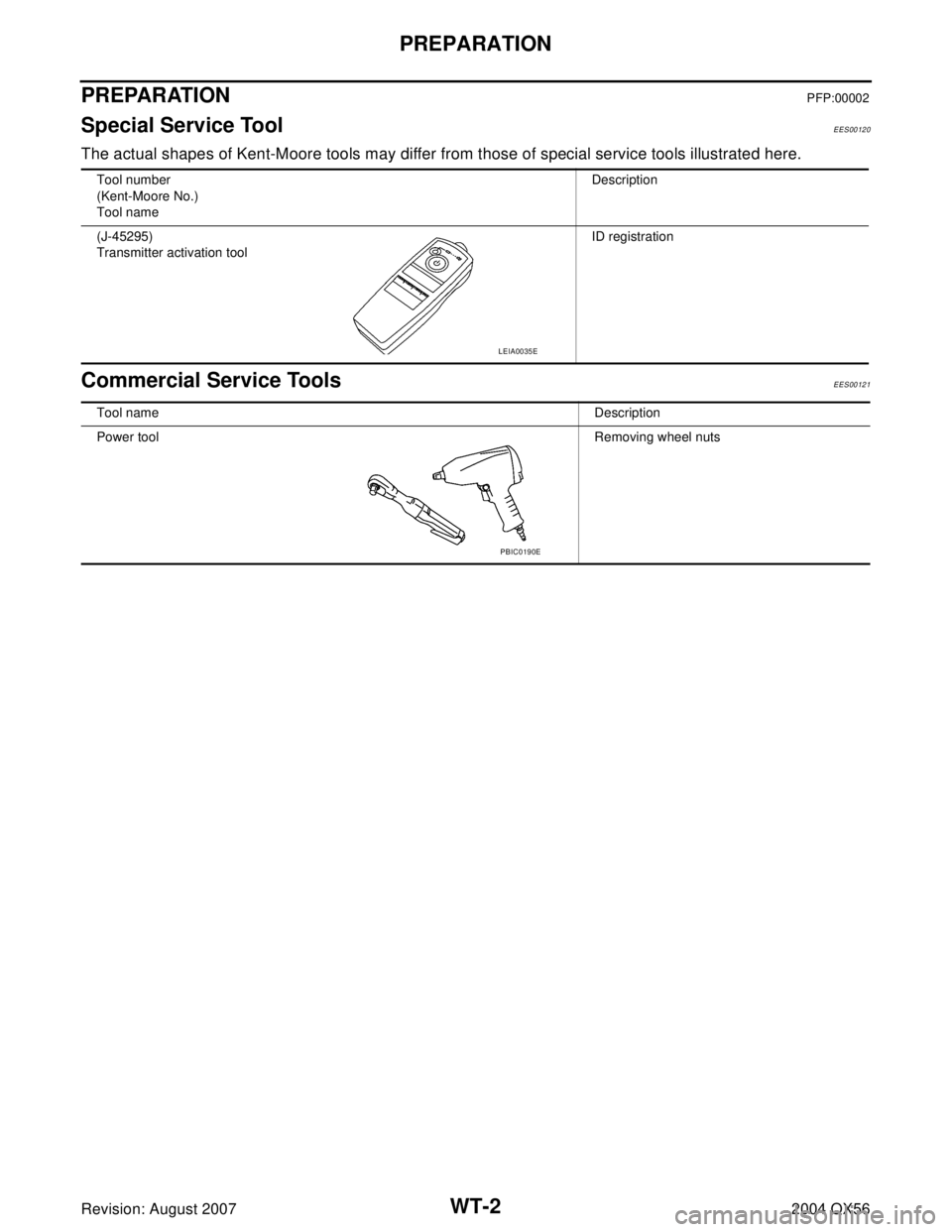
PREPARATIONPFP:00002
Special Service ToolEES00120
The actual shapes of Kent-Moore tools may differ from those of special service tools illustrated here.
Commercial Service ToolsEES00121
Tool number
(Kent-Moore No.)
Tool nameDescription
(J-45295)
Transmitter activation toolID registration
LEIA0035E
Tool nameDescription
Power toolRemoving wheel nuts
PBIC0190E