Page 1771 of 3371
EC-580Revision: August 2007
DTC P2138 APP SENSOR
2004 QX56
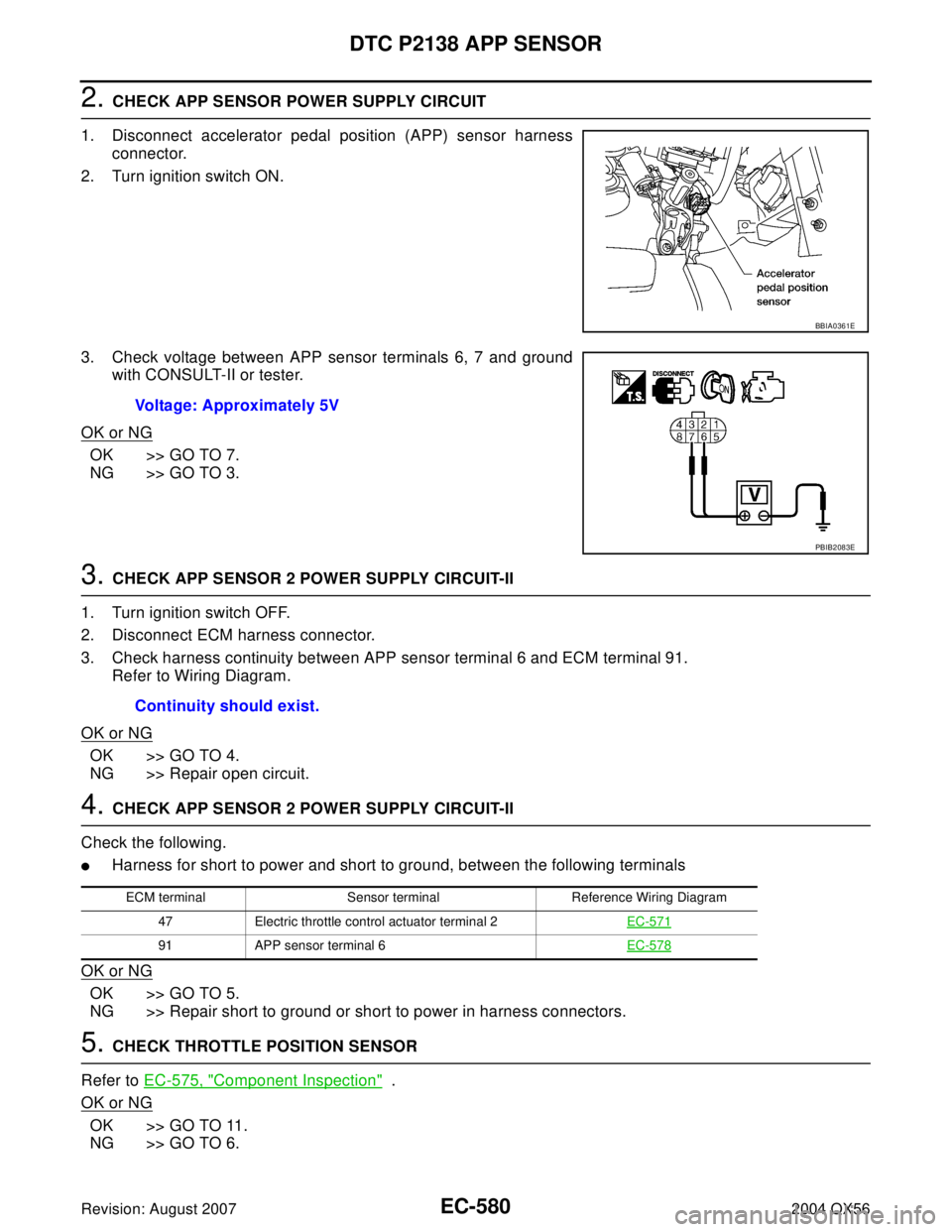
2. CHECK APP SENSOR POWER SUPPLY CIRCUIT
1. Disconnect accelerator pedal position (APP) sensor harness
connector.
2. Turn ignition switch ON.
3. Check voltage between APP sensor terminals 6, 7 and ground
with CONSULT-II or tester.
OK or NG
OK >> GO TO 7.
NG >> GO TO 3.
3. CHECK APP SENSOR 2 POWER SUPPLY CIRCUIT-II
1. Turn ignition switch OFF.
2. Disconnect ECM harness connector.
3. Check harness continuity between APP sensor terminal 6 and ECM terminal 91.
Refer to Wiring Diagram.
OK or NG
OK >> GO TO 4.
NG >> Repair open circuit.
4. CHECK APP SENSOR 2 POWER SUPPLY CIRCUIT-II
Check the following.
�Harness for short to power and short to ground, between the following terminals
OK or NG
OK >> GO TO 5.
NG >> Repair short to ground or short to power in harness connectors.
5. CHECK THROTTLE POSITION SENSOR
Refer to EC-575, "
Component Inspection" .
OK or NG
OK >> GO TO 11.
NG >> GO TO 6.
BBIA0361E
Voltage: Approximately 5V
PBIB2083E
Continuity should exist.
ECM terminal Sensor terminal Reference Wiring Diagram
47 Electric throttle control actuator terminal 2EC-571
91 APP sensor terminal 6EC-578
Page 1772 of 3371
DTC P2138 APP SENSOR
EC-581
C
D
E
F
G
H
I
J
K
L
MA
EC
Revision: August 20072004 QX56
6. REPLACE ELECTRIC THROTTLE CONTROL ACTUATOR
1. Replace the electric throttle control actuator.
2. Perform EC-44, "
Throttle Valve Closed Position Learning" .
3. Perform EC-44, "
Idle Air Volume Learning" .
>>INSPECTION END
7. CHECK APP SENSOR GROUND CIRCUIT FOR OPEN AND SHORT
1. Turn ignition switch OFF.
2. Disconnect ECM harness connector.
3. Check harness continuity between ECM terminal 82 and APP sensor terminal 1, ECM terminal 83 and
APP sensor terminal 3.
Refer to Wiring Diagram.
4. Also check harness for short to ground and short to power.
OK or NG
OK >> GO TO 8.
NG >> Repair open circuit or short to ground or short to power in harness or connectors.
8. CHECK APP SENSOR INPUT SIGNAL CIRCUIT FOR OPEN AND SHORT
1. Check harness continuity between ECM terminal 106 and APP sensor terminal 2, ECM terminal 98 and
APP sensor terminal 5.
Refer to Wiring Diagram.
2. Also check harness for short to ground and short to power.
OK or NG
OK >> GO TO 9.
NG >> Repair open circuit or short to ground or short to power in harness or connectors.
9. CHECK ACCELERATOR PEDAL POSITION SENSOR
Refer to EC-561, "
Component Inspection" .
OK or NG
OK >> GO TO 11.
NG >> GO TO 10.
10. REPLACE ACCELERATOR PEDAL ASSEMBLY
1. Replace the accelerator pedal assembly.
2. Perform EC-44, "
Accelerator Pedal Released Position Learning" .
3. Perform EC-44, "
Throttle Valve Closed Position Learning" .
4. Perform EC-44, "
Idle Air Volume Learning" .
>>INSPECTION END
11 . CHECK INTERMITTENT INCIDENT
Refer to EC-127, "
TROUBLE DIAGNOSIS FOR INTERMITTENT INCIDENT" .
>>INSPECTION END Continuity should exist.
Continuity should exist.
Page 1775 of 3371
EC-584Revision: August 2007
IGNITION SIGNAL
2004 QX56
Wiring DiagramUBS00HD1
BBWA1710E
Page 1782 of 3371
IGNITION SIGNAL
EC-591
C
D
E
F
G
H
I
J
K
L
MA
EC
Revision: August 20072004 QX56
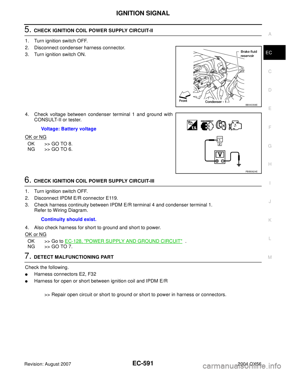
5. CHECK IGNITION COIL POWER SUPPLY CIRCUIT-II
1. Turn ignition switch OFF.
2. Disconnect condenser harness connector.
3. Turn ignition switch ON.
4. Check voltage between condenser terminal 1 and ground with
CONSULT-II or tester.
OK or NG
OK >> GO TO 8.
NG >> GO TO 6.
6. CHECK IGNITION COIL POWER SUPPLY CIRCUIT-III
1. Turn ignition switch OFF.
2. Disconnect IPDM E/R connector E119.
3. Check harness continuity between IPDM E/R terminal 4 and condenser terminal 1.
Refer to Wiring Diagram.
4. Also check harness for short to ground and short to power.
OK or NG
OK >> Go to EC-128, "POWER SUPPLY AND GROUND CIRCUIT" .
NG >> GO TO 7.
7. DETECT MALFUNCTIONING PART
Check the following.
�Harness connectors E2, F32
�Harness for open or short between ignition coil and IPDM E/R
>> Repair open circuit or short to ground or short to power in harness or connectors.
BBIA0358E
Voltage: Battery voltage
PBIB0624E
Continuity should exist.
Page 1783 of 3371
EC-592Revision: August 2007
IGNITION SIGNAL
2004 QX56
8. CHECK CONDENSER GROUND CIRCUIT FOR OPEN AND SHORT
1. Turn ignition switch OFF.
2. Check harness continuity between condenser terminal 2 and engine ground.
Refer to Wiring Diagram.
3. Also check harness for short to power.
OK or NG
OK >> GO TO 9.
NG >> Repair open circuit or short to power in harness or connectors.
9. CHECK CONDENSER
Refer to EC-593, "
Component Inspection" .
OK or NG
OK >> GO TO 10.
NG >> Replace condenser.
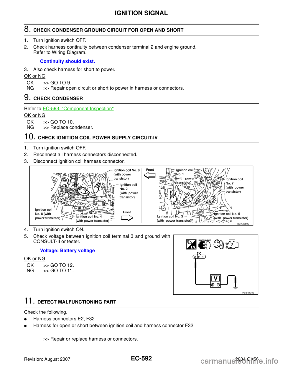
10. CHECK IGNITION COIL POWER SUPPLY CIRCUIT-IV
1. Turn ignition switch OFF.
2. Reconnect all harness connectors disconnected.
3. Disconnect ignition coil harness connector.
4. Turn ignition switch ON.
5. Check voltage between ignition coil terminal 3 and ground with
CONSULT-II or tester.
OK or NG
OK >> GO TO 12.
NG >> GO TO 11.
11 . DETECT MALFUNCTIONING PART
Check the following.
�Harness connectors E2, F32
�Harness for open or short between ignition coil and harness connector F32
>> Repair or replace harness or connectors. Continuity should exist.
Voltage: Battery voltage
BBIA0359E
PBIB0138E
Page 1784 of 3371
IGNITION SIGNAL
EC-593
C
D
E
F
G
H
I
J
K
L
MA
EC
Revision: August 20072004 QX56
12. CHECK IGNITION COIL GROUND CIRCUIT FOR OPEN AND SHORT
1. Turn ignition switch OFF.
2. Check harness continuity between ignition coil terminal 2 and engine ground.
Refer to Wiring Diagram.
3. Also check harness for short to power.
OK or NG
OK >> GO TO 13.
NG >> Repair open circuit or short to power in harness or connectors.
13. CHECK IGNITION COIL OUTPUT SIGNAL CIRCUIT FOR OPEN AND SHORT
1. Disconnect ECM harness connector.
2. Check harness continuity between ECM terminals 46, 60, 61, 62, 65, 79, 80, 81 and ignition coil terminal
1.
Refer to Wiring Diagram.
3. Also check harness for short to ground and short to power.
OK or NG
OK >> GO TO 14.
NG >> Repair open circuit or short to ground or short to power in harness or connectors.
14. CHECK IGNITION COIL WITH POWER TRANSISTOR
Refer to EC-593, "
Component Inspection" .
OK or NG
OK >> GO TO 15.
NG >> Replace ignition coil with power transistor.
15. CHECK INTERMITTENT INCIDENT
Refer to EC-127, "
TROUBLE DIAGNOSIS FOR INTERMITTENT INCIDENT" .
>>INSPECTION END
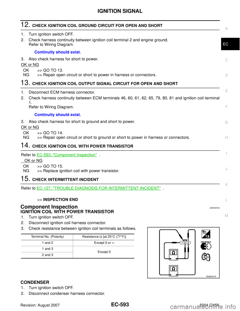
Component InspectionUBS00HD3
IGNITION COIL WITH POWER TRANSISTOR
1. Turn ignition switch OFF.
2. Disconnect ignition coil harness connector.
3. Check resistance between ignition coil terminals as follows.
CONDENSER
1. Turn ignition switch OFF.
2. Disconnect condenser harness connector.Continuity should exist.
Continuity should exist.
Terminal No. (Polarity) Resistance Ω [at 25°C (77°F)]
1 and 2 Except 0 or ∞
1 and 3
Except 0
2 and 3
PBIB0847E
Page 1787 of 3371
EC-596Revision: August 2007
INJECTOR CIRCUIT
2004 QX56
Wiring DiagramUBS00HD7
BBWA11 90 E
Page 1790 of 3371
INJECTOR CIRCUIT
EC-599
C
D
E
F
G
H
I
J
K
L
MA
EC
Revision: August 20072004 QX56
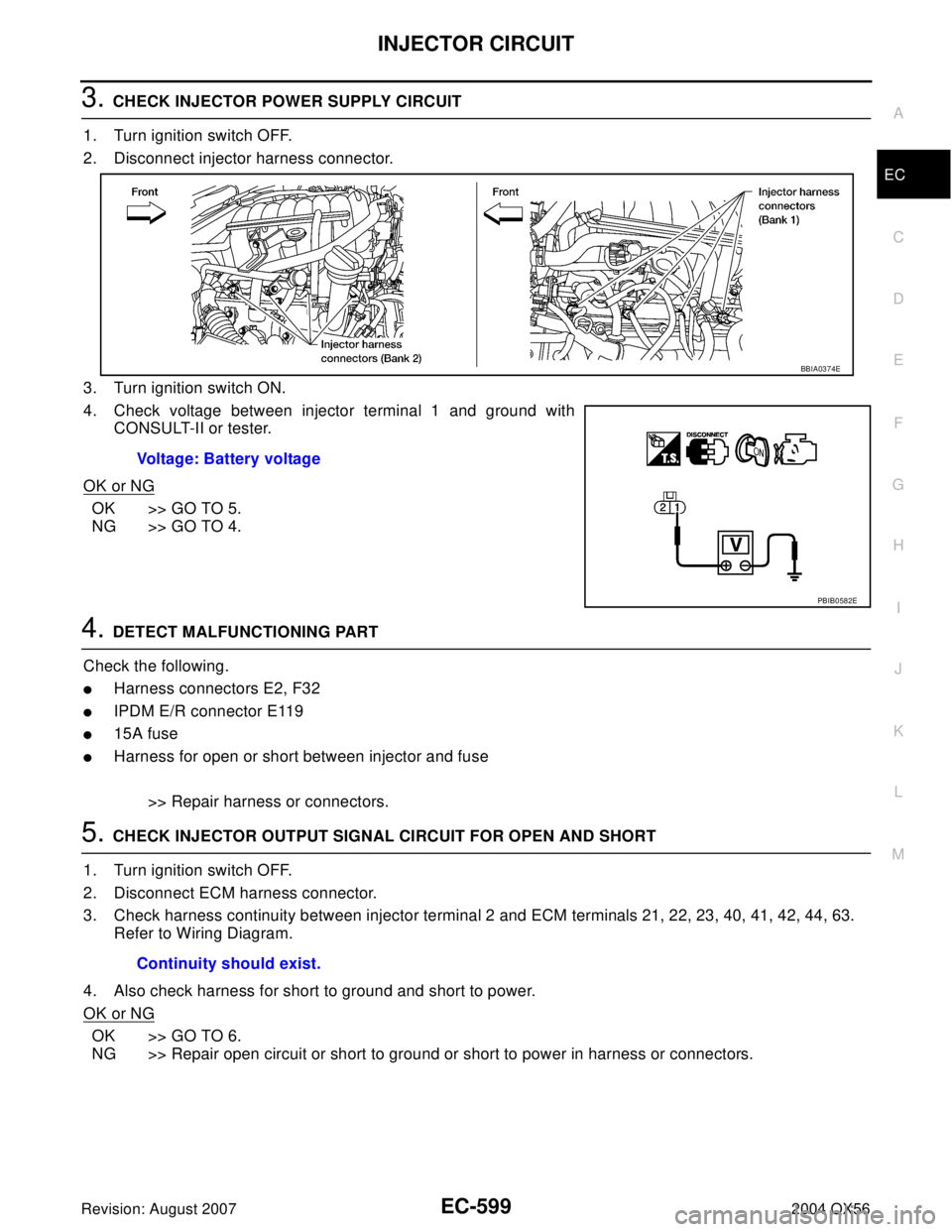
3. CHECK INJECTOR POWER SUPPLY CIRCUIT
1. Turn ignition switch OFF.
2. Disconnect injector harness connector.
3. Turn ignition switch ON.
4. Check voltage between injector terminal 1 and ground with
CONSULT-II or tester.
OK or NG
OK >> GO TO 5.
NG >> GO TO 4.
4. DETECT MALFUNCTIONING PART
Check the following.
�Harness connectors E2, F32
�IPDM E/R connector E119
�15A fuse
�Harness for open or short between injector and fuse
>> Repair harness or connectors.
5. CHECK INJECTOR OUTPUT SIGNAL CIRCUIT FOR OPEN AND SHORT
1. Turn ignition switch OFF.
2. Disconnect ECM harness connector.
3. Check harness continuity between injector terminal 2 and ECM terminals 21, 22, 23, 40, 41, 42, 44, 63.
Refer to Wiring Diagram.
4. Also check harness for short to ground and short to power.
OK or NG
OK >> GO TO 6.
NG >> Repair open circuit or short to ground or short to power in harness or connectors.Voltage: Battery voltage
BBIA0374E
PBIB0582E
Continuity should exist.