Page 1983 of 3371
EM-100Revision: August 2007
SERVICE DATA AND SPECIFICATIONS (SDS)
2004 QX56
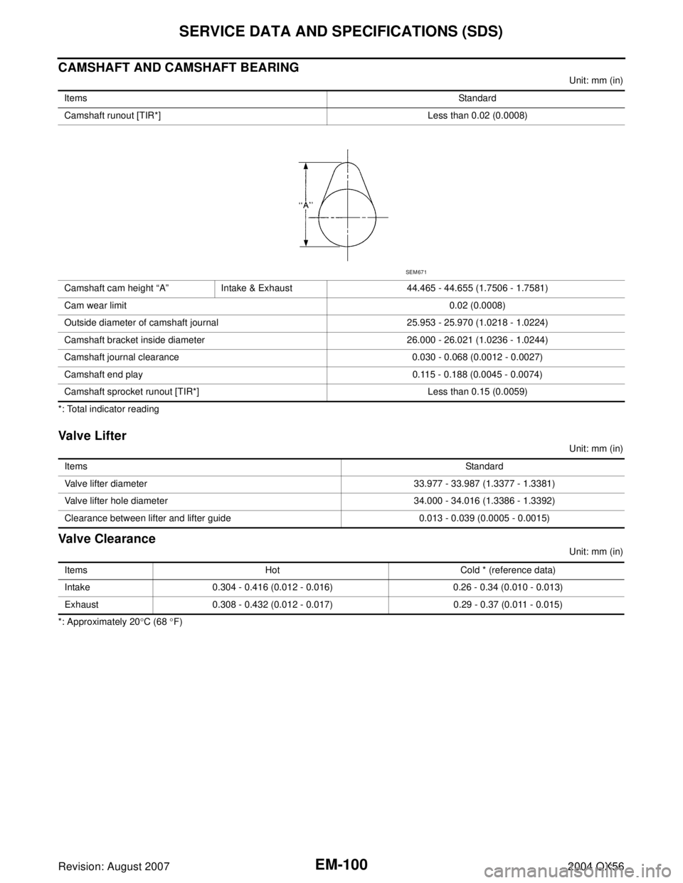
CAMSHAFT AND CAMSHAFT BEARING
Unit: mm (in)
*: Total indicator reading
Valve Lifter
Unit: mm (in)
Valve Clearance
Unit: mm (in)
*: Approximately 20°C (68 °F) ItemsStandard
Camshaft runout [TIR*] Less than 0.02 (0.0008)
Camshaft cam height “A” Intake & Exhaust 44.465 - 44.655 (1.7506 - 1.7581)
Cam wear limit0.02 (0.0008)
Outside diameter of camshaft journal 25.953 - 25.970 (1.0218 - 1.0224)
Camshaft bracket inside diameter 26.000 - 26.021 (1.0236 - 1.0244)
Camshaft journal clearance 0.030 - 0.068 (0.0012 - 0.0027)
Camshaft end play 0.115 - 0.188 (0.0045 - 0.0074)
Camshaft sprocket runout [TIR*] Less than 0.15 (0.0059)
SEM 67 1
ItemsStandard
Valve lifter diameter 33.977 - 33.987 (1.3377 - 1.3381)
Valve lifter hole diameter 34.000 - 34.016 (1.3386 - 1.3392)
Clearance between lifter and lifter guide 0.013 - 0.039 (0.0005 - 0.0015)
Items Hot Cold * (reference data)
Intake 0.304 - 0.416 (0.012 - 0.016) 0.26 - 0.34 (0.010 - 0.013)
Exhaust 0.308 - 0.432 (0.012 - 0.017) 0.29 - 0.37 (0.011 - 0.015)
Page 1985 of 3371
EM-102Revision: August 2007
SERVICE DATA AND SPECIFICATIONS (SDS)
2004 QX56
CYLINDER HEAD
Unit: mm (in)
Valve Dimensions
Unit: mm (in) Items Standard Limit
Head surface distortion 0.03 (0.0012) 0.1 (0.004)
Nominal cylinder head height “H” 126.3 (4.97)
KBIA2554E
Valve head diameter “D”Intake 37.0 - 37.3 (1.457 - 1.469)
Exhaust 31.2 - 31.5 (1.228 - 1.240)
Valve length “L”Intake 96.21- 96.71 (3.7878 - 3.8075)
Exhaust 93.74 - 94.24 (3.6905 - 3.7102)
Valve stem diameter “d”Intake 5.965 - 5.980 (0.2348 - 0.2354)
Exhaust 5.955 - 5.970 (0.2344 - 0.2350)
Valve seat angle “α”Intake
45°15′ - 45°45′
Exhaust
Valve margin “T”Intake 1.1 (0.043)
Exhaust 1.3 (0.051)
SEM188
Page 1986 of 3371
SERVICE DATA AND SPECIFICATIONS (SDS)
EM-103
C
D
E
F
G
H
I
J
K
L
MA
EM
Revision: August 20072004 QX56
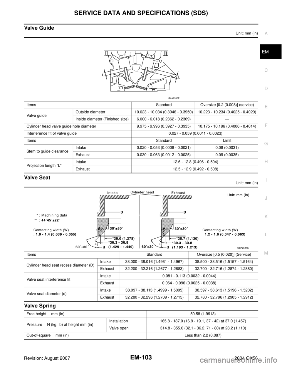
Valve Guide
Unit: mm (in)
Valve Seat
Unit: mm (in)
Valve Spring
Items Standard Oversize [0.2 (0.008)] (service)
Valve guideOutside diameter 10.023 - 10.034 (0.3946 - 0.3950) 10.223 - 10.234 (0.4025 - 0.4029)
Inside diameter (Finished size) 6.000 - 6.018 (0.2362 - 0.2369) —
Cylinder head valve guide hole diameter 9.975 - 9.996 (0.3927 - 0.3935) 10.175 - 10.196 (0.4006 - 0.4014)
Interference fit of valve guide 0.027 - 0.059 (0.0011 - 0.0023)
Items Standard Limit
Stem to guide clearanceIntake 0.020 - 0.053 (0.0008 - 0.0021) 0.08 (0.0031)
Exhaust 0.030 - 0.063 (0.0012 - 0.0025) 0.09 (0.0035)
Projection length “L”Intake 12.6 - 12.8 (0.496 - 0.504)
Exhaust 12.5 - 12.9 (0.492 - 0.508)
KBIA2555E
Items Standard Oversize [0.5 (0.020)] (Service)
Cylinder head seat recess diameter (D)Intake 38.000 - 38.016 (1.4961 - 1.4967) 38.500 - 38.516 (1.5157 - 1.5164)
Exhaust 32.200 - 32.216 (1.2677 - 1.2683) 32.700 - 32.716 (1.2874 - 1.2880)
Valve seat interference fitIntake 0.081 - 0.113 (0.0032 - 0.0044)
Exhaust 0.064 - 0.096 (0.0025 - 0.0038)
Valve seat diameter (d)Intake 38.097 - 38.113 (1.4999 - 1.5005) 38.597 - 38.613 (1.5196 - 1.5202)
Exhaust 32.280 - 32.296 (1.2709 - 1.2715) 32.780 - 32.796 (1.2905 - 1.2912)
KBIA2541E
Free height mm (in)50.58 (1.9913)
Pressure N (kg, lb) at height mm (in)Installation 165.8 - 187.0 (16.9 - 19.1, 37 - 42) at 37.0 (1.457)
Valve open 314.8 - 355.0 (32.1 - 36.2, 71 - 80) at 28.2 (1.110)
Out-of-square mm (in) Less than 2.2 (0.087)
Page 1987 of 3371
EM-104Revision: August 2007
SERVICE DATA AND SPECIFICATIONS (SDS)
2004 QX56
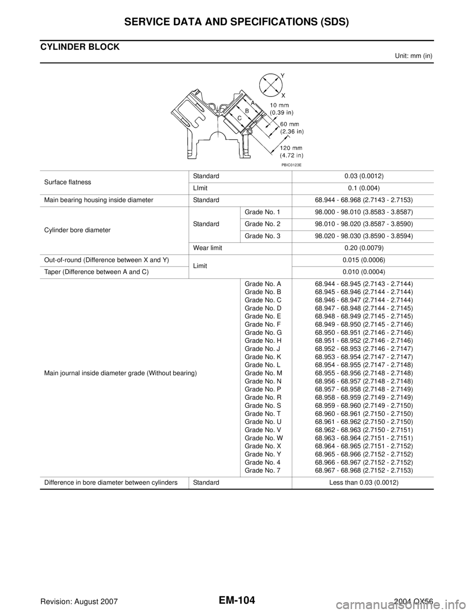
CYLINDER BLOCK
Unit: mm (in)
Surface flatnessStandard 0.03 (0.0012)
LImit 0.1 (0.004)
Main bearing housing inside diameter Standard 68.944 - 68.968 (2.7143 - 2.7153)
Cylinder bore diameterStandardGrade No. 1 98.000 - 98.010 (3.8583 - 3.8587)
Grade No. 2 98.010 - 98.020 (3.8587 - 3.8590)
Grade No. 3 98.020 - 98.030 (3.8590 - 3.8594)
Wear limit 0.20 (0.0079)
Out-of-round (Difference between X and Y)
Limit0.015 (0.0006)
Taper (Difference between A and C) 0.010 (0.0004)
Main journal inside diameter grade (Without bearing)Grade No. A
Grade No. B
Grade No. C
Grade No. D
Grade No. E
Grade No. F
Grade No. G
Grade No. H
Grade No. J
Grade No. K
Grade No. L
Grade No. M
Grade No. N
Grade No. P
Grade No. R
Grade No. S
Grade No. T
Grade No. U
Grade No. V
Grade No. W
Grade No. X
Grade No. Y
Grade No. 4
Grade No. 768.944 - 68.945 (2.7143 - 2.7144)
68.945 - 68.946 (2.7144 - 2.7144)
68.946 - 68.947 (2.7144 - 2.7144)
68.947 - 68.948 (2.7144 - 2.7145)
68.948 - 68.949 (2.7145 - 2.7145)
68.949 - 68.950 (2.7145 - 2.7146)
68.950 - 68.951 (2.7146 - 2.7146)
68.951 - 68.952 (2.7146 - 2.7146)
68.952 - 68.953 (2.7146 - 2.7147)
68.953 - 68.954 (2.7147 - 2.7147)
68.954 - 68.955 (2.7147 - 2.7148)
68.955 - 68.956 (2.7148 - 2.7148)
68.956 - 68.957 (2.7148 - 2.7148)
68.957 - 68.958 (2.7148 - 2.7149)
68.958 - 68.959 (2.7149 - 2.7149)
68.959 - 68.960 (2.7149 - 2.7150)
68.960 - 68.961 (2.7150 - 2.7150)
68.961 - 68.962 (2.7150 - 2.7150)
68.962 - 68.963 (2.7150 - 2.7151)
68.963 - 68.964 (2.7151 - 2.7151)
68.964 - 68.965 (2.7151 - 2.7152)
68.965 - 68.966 (2.7152 - 2.7152)
68.966 - 68.967 (2.7152 - 2.7152)
68.967 - 68.968 (2.7152 - 2.7153)
Difference in bore diameter between cylinders Standard Less than 0.03 (0.0012)
PBIC0123E
Page 1988 of 3371
SERVICE DATA AND SPECIFICATIONS (SDS)
EM-105
C
D
E
F
G
H
I
J
K
L
MA
EM
Revision: August 20072004 QX56
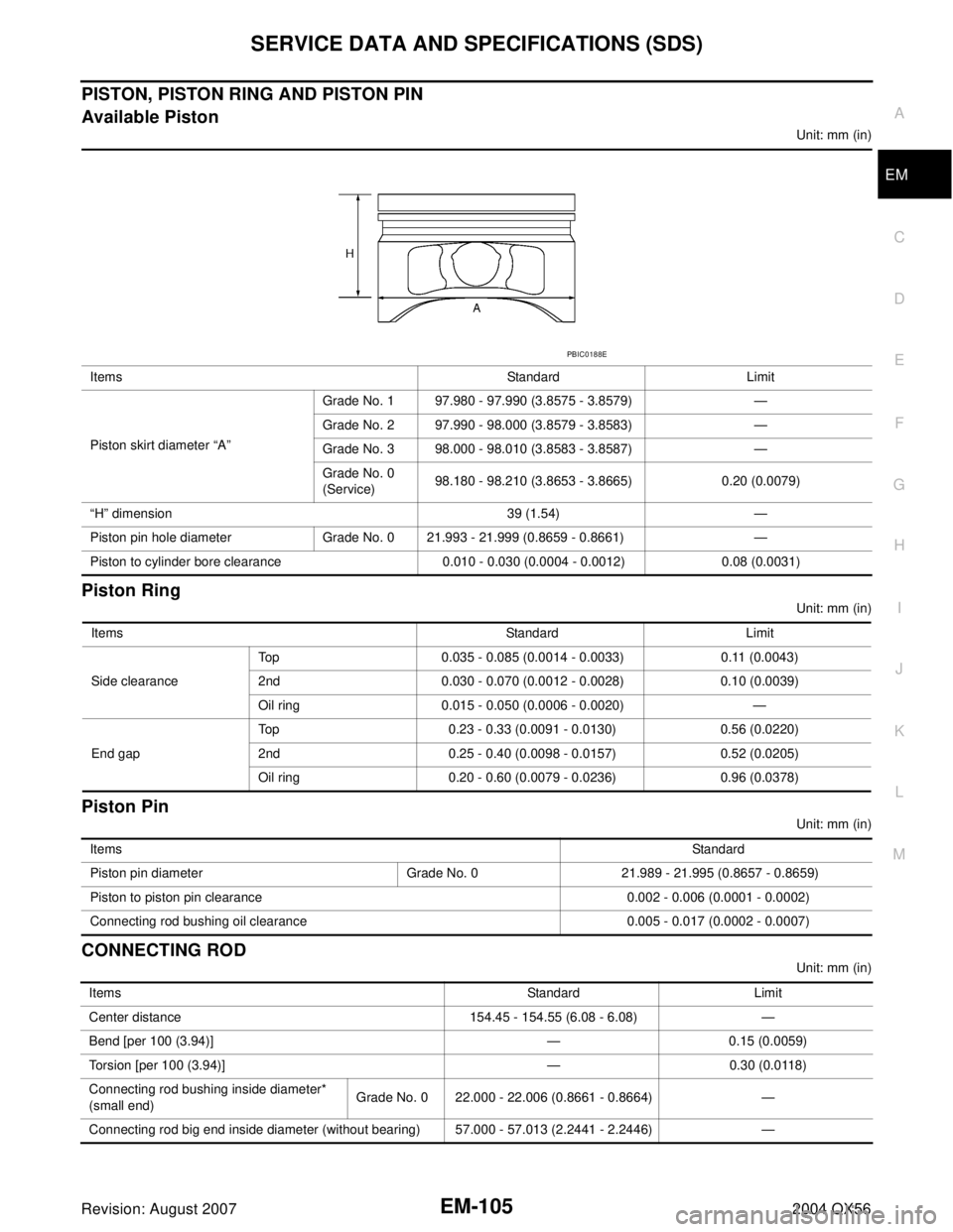
PISTON, PISTON RING AND PISTON PIN
Available Piston
Unit: mm (in)
Piston Ring
Unit: mm (in)
Piston Pin
Unit: mm (in)
CONNECTING ROD
Unit: mm (in) Items Standard Limit
Piston skirt diameter “A”Grade No. 1 97.980 - 97.990 (3.8575 - 3.8579) —
Grade No. 2 97.990 - 98.000 (3.8579 - 3.8583) —
Grade No. 3 98.000 - 98.010 (3.8583 - 3.8587) —
Grade No. 0
(Service)98.180 - 98.210 (3.8653 - 3.8665) 0.20 (0.0079)
“H” dimension 39 (1.54) —
Piston pin hole diameter Grade No. 0 21.993 - 21.999 (0.8659 - 0.8661) —
Piston to cylinder bore clearance 0.010 - 0.030 (0.0004 - 0.0012) 0.08 (0.0031)
PBIC0188E
Items Standard Limit
Side clearanceTop 0.035 - 0.085 (0.0014 - 0.0033) 0.11 (0.0043)
2nd 0.030 - 0.070 (0.0012 - 0.0028) 0.10 (0.0039)
Oil ring 0.015 - 0.050 (0.0006 - 0.0020) —
End gapTop 0.23 - 0.33 (0.0091 - 0.0130) 0.56 (0.0220)
2nd 0.25 - 0.40 (0.0098 - 0.0157) 0.52 (0.0205)
Oil ring 0.20 - 0.60 (0.0079 - 0.0236) 0.96 (0.0378)
ItemsStandard
Piston pin diameter Grade No. 0 21.989 - 21.995 (0.8657 - 0.8659)
Piston to piston pin clearance 0.002 - 0.006 (0.0001 - 0.0002)
Connecting rod bushing oil clearance 0.005 - 0.017 (0.0002 - 0.0007)
Items Standard Limit
Center distance 154.45 - 154.55 (6.08 - 6.08) —
Bend [per 100 (3.94)] — 0.15 (0.0059)
Torsion [per 100 (3.94)] — 0.30 (0.0118)
Connecting rod bushing inside diameter*
(small end)Grade No. 0 22.000 - 22.006 (0.8661 - 0.8664) —
Connecting rod big end inside diameter (without bearing) 57.000 - 57.013 (2.2441 - 2.2446) —
Page 1991 of 3371
EM-108Revision: August 2007
SERVICE DATA AND SPECIFICATIONS (SDS)
2004 QX56
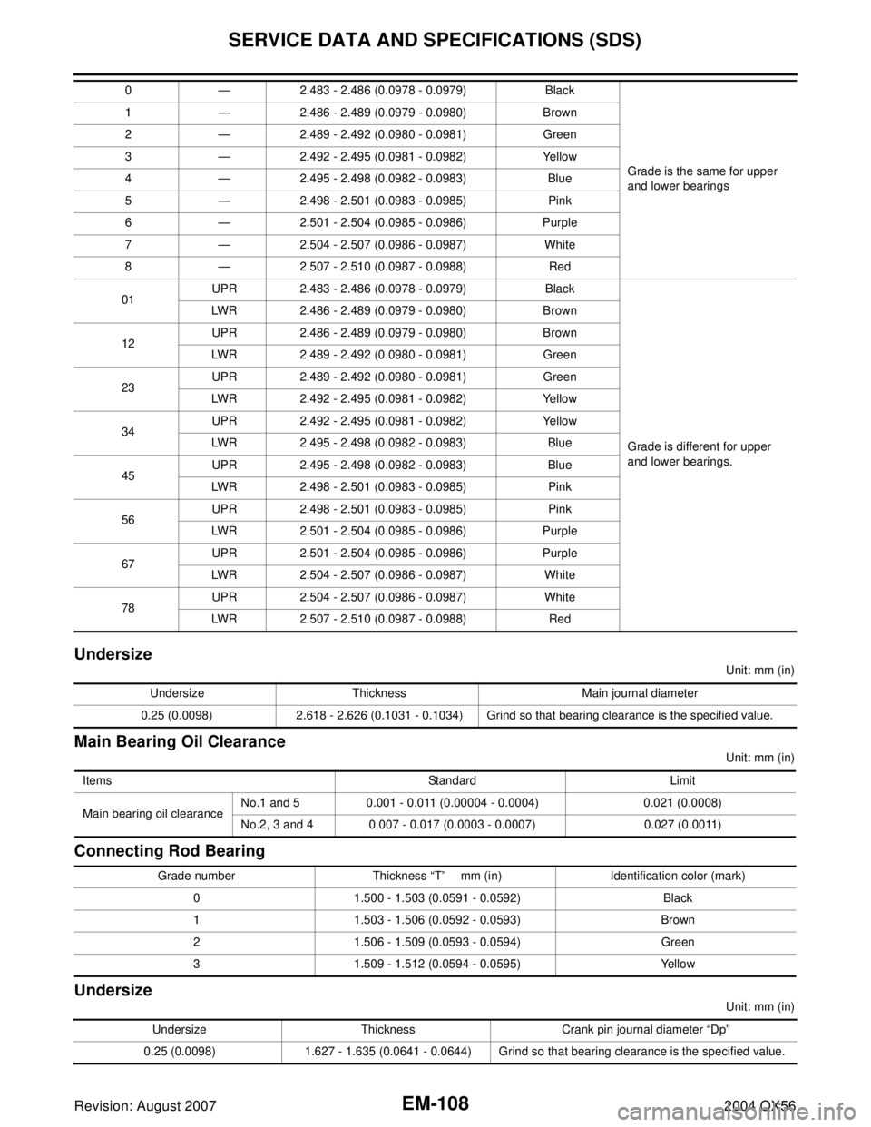
Undersize
Unit: mm (in)
Main Bearing Oil Clearance
Unit: mm (in)
Connecting Rod Bearing
Undersize
Unit: mm (in) 0 — 2.483 - 2.486 (0.0978 - 0.0979) Black
Grade is the same for upper
and lower bearings 1 — 2.486 - 2.489 (0.0979 - 0.0980) Brown
2 — 2.489 - 2.492 (0.0980 - 0.0981) Green
3 — 2.492 - 2.495 (0.0981 - 0.0982) Yellow
4 — 2.495 - 2.498 (0.0982 - 0.0983) Blue
5 — 2.498 - 2.501 (0.0983 - 0.0985) Pink
6 — 2.501 - 2.504 (0.0985 - 0.0986) Purple
7 — 2.504 - 2.507 (0.0986 - 0.0987) White
8 — 2.507 - 2.510 (0.0987 - 0.0988) Red
01UPR 2.483 - 2.486 (0.0978 - 0.0979) Black
Grade is different for upper
and lower bearings. LWR 2.486 - 2.489 (0.0979 - 0.0980) Brown
12UPR 2.486 - 2.489 (0.0979 - 0.0980) Brown
LWR 2.489 - 2.492 (0.0980 - 0.0981) Green
23UPR 2.489 - 2.492 (0.0980 - 0.0981) Green
LWR 2.492 - 2.495 (0.0981 - 0.0982) Yellow
34UPR 2.492 - 2.495 (0.0981 - 0.0982) Yellow
LWR 2.495 - 2.498 (0.0982 - 0.0983) Blue
45UPR 2.495 - 2.498 (0.0982 - 0.0983) Blue
LWR 2.498 - 2.501 (0.0983 - 0.0985) Pink
56UPR 2.498 - 2.501 (0.0983 - 0.0985) Pink
LWR 2.501 - 2.504 (0.0985 - 0.0986) Purple
67UPR 2.501 - 2.504 (0.0985 - 0.0986) Purple
LWR 2.504 - 2.507 (0.0986 - 0.0987) White
78UPR 2.504 - 2.507 (0.0986 - 0.0987) White
LWR 2.507 - 2.510 (0.0987 - 0.0988) Red
Undersize Thickness Main journal diameter
0.25 (0.0098) 2.618 - 2.626 (0.1031 - 0.1034) Grind so that bearing clearance is the specified value.
Items Standard Limit
Main bearing oil clearanceNo.1 and 5 0.001 - 0.011 (0.00004 - 0.0004) 0.021 (0.0008)
No.2, 3 and 4 0.007 - 0.017 (0.0003 - 0.0007) 0.027 (0.0011)
Grade number Thickness “T” mm (in) Identification color (mark)
0 1.500 - 1.503 (0.0591 - 0.0592) Black
1 1.503 - 1.506 (0.0592 - 0.0593) Brown
2 1.506 - 1.509 (0.0593 - 0.0594) Green
3 1.509 - 1.512 (0.0594 - 0.0595) Yellow
Undersize Thickness Crank pin journal diameter “Dp”
0.25 (0.0098) 1.627 - 1.635 (0.0641 - 0.0644) Grind so that bearing clearance is the specified value.
Page 2027 of 3371
FFD-16
FRONT FINAL DRIVE ASSEMBLY
Revision: August 20072004 QX56
Backlash
1. Remove carrier cover. Refer to FFD-11, "REMOVAL" .
2. Fit a dial indicator to the drive gear face to measure the back-
lash.
�If the backlash is outside of the specified value, use each side
bearing adjust nut.
Companion Flange Runout
1. Fit a dial indicator onto the companion flange face (inner side of
the propeller shaft mounting bolt holes).
2. Rotate companion flange to check for runout.
3. Fit a test indicator to the inner side of companion flange (socket
diameter).
4. Rotate companion flange to check for runout.
SDIA1796E
Backlash: 0.12 - 0.20 mm (0.0050 - 0.0079 in)
SDIA3203E
When the backlash is large:
Loosen adjust nut A and tighten adjust nut B.
When the backlash is small:
Loosen adjust nut B and tighten adjust nut A.
SDIA2262E
Runout limit: 0.10 mm (0.0039 in)
Runout limit: 0.13 mm (0.0051 in)
PDIA0646E
Page 2050 of 3371
FUEL LEVEL SENSOR UNIT, FUEL FILTER AND FUEL PUMP ASSEMBLY
FL-5
C
D
E
F
G
H
I
J
K
L
MA
FL
Revision: August 20072004 QX56
FUEL LEVEL SENSOR UNIT, FUEL FILTER AND FUEL PUMP ASSEMBLYPFP:17042
Removal and InstallationEBS00IKP
REMOVAL
WA RN ING:
Follow the “General Precautions” before working on the fuel system. Refer to FL-3, "
General Precau-
tions" .
1. Remove the fuel filler cap to release the pressure from inside the fuel tank.
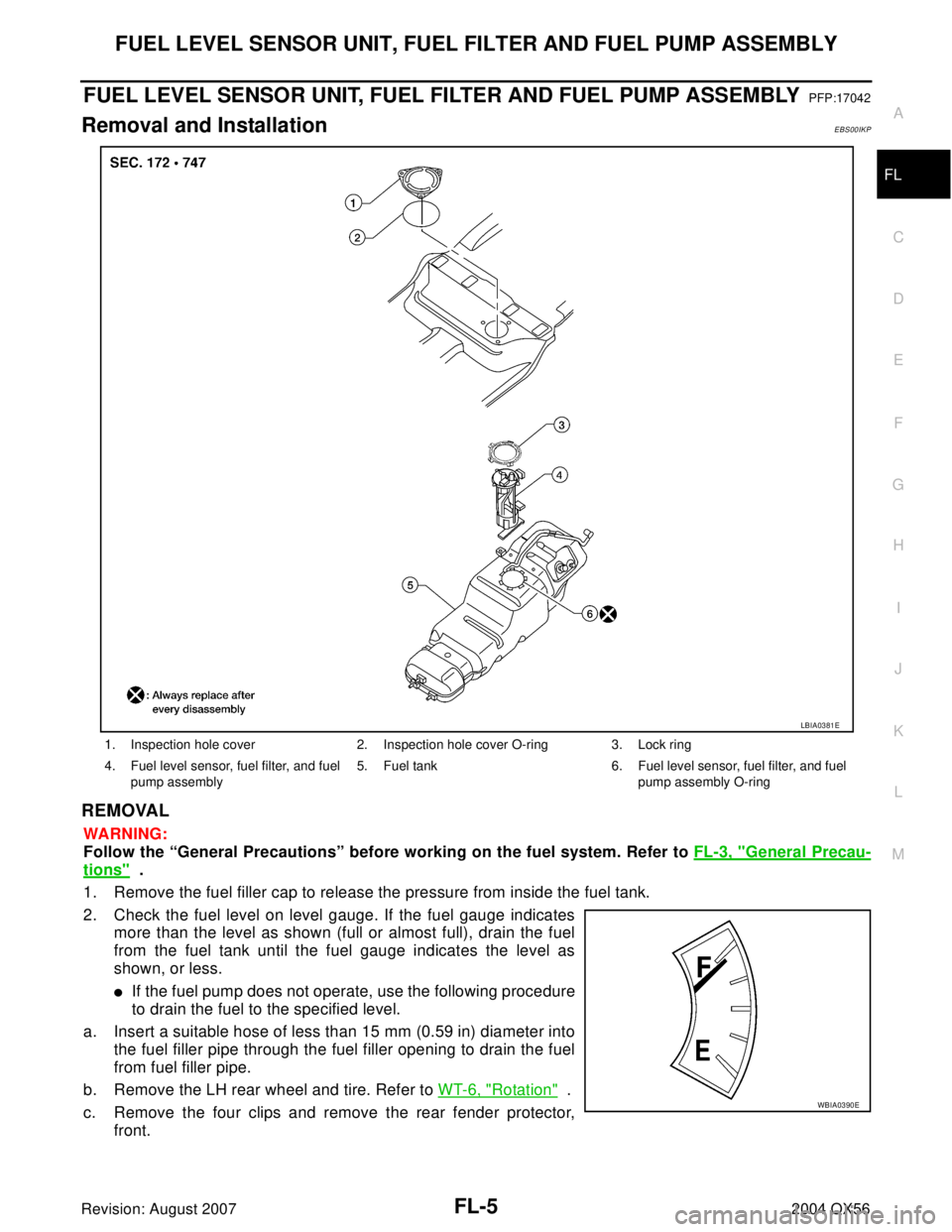
2. Check the fuel level on level gauge. If the fuel gauge indicates
more than the level as shown (full or almost full), drain the fuel
from the fuel tank until the fuel gauge indicates the level as
shown, or less.
�If the fuel pump does not operate, use the following procedure
to drain the fuel to the specified level.
a. Insert a suitable hose of less than 15 mm (0.59 in) diameter into
the fuel filler pipe through the fuel filler opening to drain the fuel
from fuel filler pipe.
b. Remove the LH rear wheel and tire. Refer to WT-6, "
Rotation" .
c. Remove the four clips and remove the rear fender protector,
front.
1. Inspection hole cover 2. Inspection hole cover O-ring 3. Lock ring
4. Fuel level sensor, fuel filter, and fuel
pump assembly5. Fuel tank 6. Fuel level sensor, fuel filter, and fuel
pump assembly O-ring
LBIA0381E
WBIA0390E