Page 2625 of 3371

MA-8
PERIODIC MAINTENANCE
Revision: August 20072004 QX56
(1) If towing a trailer, or using a car-top carrier, or driving on rough or muddy roads, change (not just inspect) oil at every 30,000 miles
(48,000 km) or 24 months.
(2) Refer to “Tire rotation” under the “General maintenance” heading earlier in this section.
Schedule 2ELS00102
EMISSION CONTROL SYSTEM MAINTENANCE
Abbreviations: R = Replace. I = Inspect. Correct or replace if necessary. [ ]: At the mileage intervals only
(1) After 60,000 miles (96,000 km) or 48 months, inspect every 15,000 miles (24,000 km) or 12 months. Replace drive belts if damaged.
(2) Maintenance-free item. For service procedures, go to FL section.
(3) After 60,000 miles (96,000 km) or 48 months, replace every 30,000 miles (48,000 km) or 24 months.
(4) If valve noise increases, inspect valve clearance.
* Maintenance items and intervals with “*” are recommended by NISSAN for reliable vehicle operation. The owner need not perform
such maintenance in order to maintain the emission warranty or manufacturer recall liability. Other maintenance items and intervals are
required. MAINTENANCE OPERATIONMAINTENANCE INTERVAL
Reference
Section
- Page
or
- Content
Title Perform at number of miles, kilometers or
months, whichever comes first.Miles x
1,000
(km x
1,000)
Months33.75
(54)
2737.5
(60)
3041.25
(66)
3345
(72)
3648.75
(78)
3952.5
(84)
4256.25
(90)
4560
(96)
48
Brake lines and cables I IMA-27
Brake pads and rotors I I I IMA-28
Automatic transmission fluid NOTE (1) I IMA-21
Transfer fluid and front final drive oil NOTE (1) I IMA-24,
MA-24
Rear final drive oil NOTE (1) I IMA-24,
MA-24
Steering gear, linkage, axle, and suspension
partsII IIMA-28,
MA-29
Tire Rotation NOTE (2)MA-27
Drive shaft boots and propeller shaft (4WD) I I I IMA-24
Exhaust system I I I IMA-21
In-cabin microfilter R RAT C - 1 4 2
MAINTENANCE OPERATIONMAINTENANCE INTERVAL
Reference
Section - Page
or - Content
Title Perform at number of miles,
kilometers or months, whichever
comes first.Miles x 1,000
(km x 1,000)
Months7.5
(12)
615
(24)
1222.5
(36)
1830
(48)
2437.5
(60)
3045
(72)
3652.5
(84)
4260
(96)
48
Drive belts NOTE (1) I*MA-12
Air cleaner filter [R] [R]MA-15
EVAP vapor lines I* I*MA-19
Fuel lines I* I*MA-15
Fuel filter NOTE (2)—
Engine coolant NOTE (3) R*MA-12
Engine oil R R R R R R R RMA-16
Engine oil filter R R R R R R R RMA-16
Spark plugs (PLATINUM-
TIPPED type)Replace every 105,000 miles (169,000 km).MA-17
Intake and exhaust valve clear-
ance*NOTE (4)EM-52
Page 2641 of 3371

MA-24
CHASSIS AND BODY MAINTENANCE
Revision: August 20072004 QX56
Checking Transfer FluidELS0010I
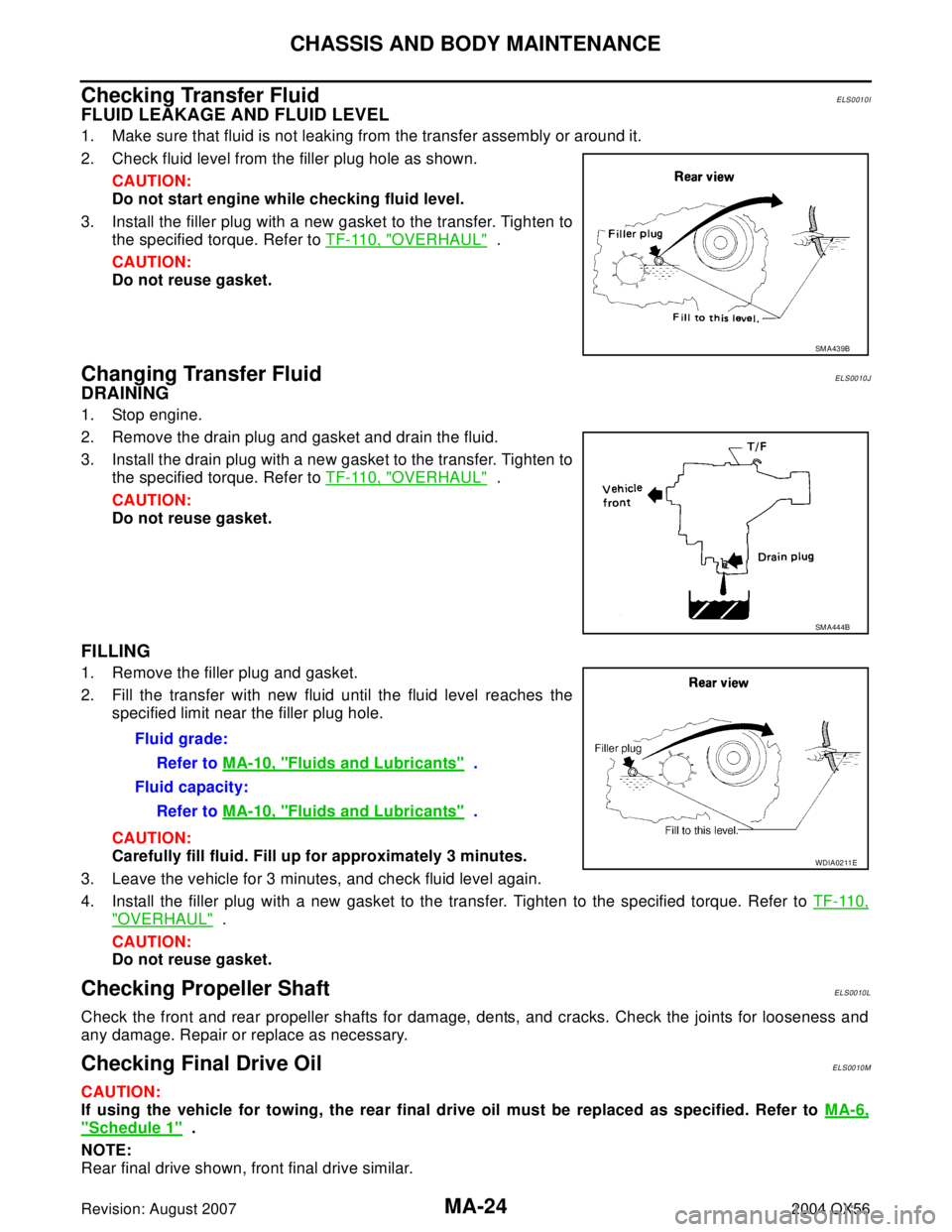
FLUID LEAKAGE AND FLUID LEVEL
1. Make sure that fluid is not leaking from the transfer assembly or around it.
2. Check fluid level from the filler plug hole as shown.
CAUTION:
Do not start engine while checking fluid level.
3. Install the filler plug with a new gasket to the transfer. Tighten to
the specified torque. Refer to TF-110, "
OVERHAUL" .
CAUTION:
Do not reuse gasket.
Changing Transfer FluidELS0010J
DRAINING
1. Stop engine.
2. Remove the drain plug and gasket and drain the fluid.
3. Install the drain plug with a new gasket to the transfer. Tighten to
the specified torque. Refer to TF-110, "
OVERHAUL" .
CAUTION:
Do not reuse gasket.
FILLING
1. Remove the filler plug and gasket.
2. Fill the transfer with new fluid until the fluid level reaches the
specified limit near the filler plug hole.
CAUTION:
Carefully fill fluid. Fill up for approximately 3 minutes.
3. Leave the vehicle for 3 minutes, and check fluid level again.
4. Install the filler plug with a new gasket to the transfer. Tighten to the specified torque. Refer to TF-110,
"OVERHAUL" .
CAUTION:
Do not reuse gasket.
Checking Propeller ShaftELS0010L
Check the front and rear propeller shafts for damage, dents, and cracks. Check the joints for looseness and
any damage. Repair or replace as necessary.
Checking Final Drive OilELS0010M
CAUTION:
If using the vehicle for towing, the rear final drive oil must be replaced as specified. Refer to MA-6,
"Schedule 1" .
NOTE:
Rear final drive shown, front final drive similar.
SM A43 9B
SM A44 4B
Fluid grade:
Refer to MA-10, "
Fluids and Lubricants" .
Fluid capacity:
Refer to MA-10, "
Fluids and Lubricants" .
WDIA0211E
Page 2642 of 3371

CHASSIS AND BODY MAINTENANCE
MA-25
C
D
E
F
G
H
I
J
K
MA
B
MA
Revision: August 20072004 QX56
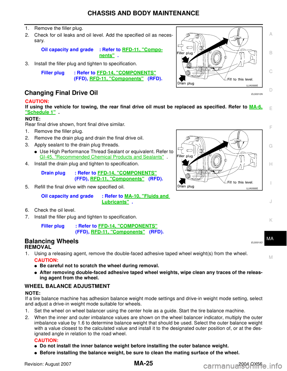
1. Remove the filler plug.
2. Check for oil leaks and oil level. Add the specified oil as neces-
sary.
3. Install the filler plug and tighten to specification.
Changing Final Drive OilELS0010N
CAUTION:
If using the vehicle for towing, the rear final drive oil must be replaced as specified. Refer to MA-6,
"Schedule 1" .
NOTE:
Rear final drive shown, front final drive similar.
1. Remove the filler plug.
2. Remove the drain plug and drain the final drive oil.
3. Apply sealant to the drain plug threads.
�Use High Performance Thread Sealant or equivalent. Refer to
GI-45, "
Recommended Chemical Products and Sealants" .
4. Install the drain plug and tighten to specification.
5. Refill the final drive with new specified oil.
6. Check the oil level.
7. Install the filler plug and tighten to specification.
Balancing WheelsELS0010O
REMOVAL
1. Using a releasing agent, remove the double-faced adhesive taped wheel weight(s) from the wheel.
CAUTION:
�Be careful not to scratch the wheel during removal.
�After removing double-faced adhesive taped wheel weights, wipe clean any traces of the releas-
ing agent from the wheel.
WHEEL BALANCE ADJUSTMENT
NOTE:
If a tire balance machine has adhesion balance weight mode settings and drive-in weight mode setting, select
and adjust a drive-in weight mode suitable for wheels.
1. Set the wheel on wheel balancer using the center hole as a guide. Start the tire balance machine.
2. When the inner and outer imbalance values are shown on the wheel balancer indicator, multiply the outer
imbalance value by 1.6 to determine balance weight that should be used. Select the outer balance weight
with a value closest to the calculated value and install it to the designated outer position of, or at the des-
ignated angle in relation to the road wheel.
CAUTION:
�Do not install the inner balance weight before installing the outer balance weight.
�Before installing the balance weight, be sure to clean the mating surface of the wheel.Oil capacity and grade : Refer to RFD-11, "
Compo-
nents" .
Filler plug : Refer to FFD-14, "
COMPONENTS"
(FFD), RFD-11, "
Components" (RFD).
LLIA0068E
Drain plug : Refer to FFD-14, "COMPONENTS"
(FFD), RFD-11, "
Components" (RFD).
Oil capacity and grade : Refer to MA-10, "
Fluids and
Lubricants" .
Filler plug : Refer to FFD-14, "
COMPONENTS"
(FFD), RFD-11, "
Components" (RFD).
LLIA0068E
Page 3285 of 3371

WT-6
WHEEL AND TIRE ASSEMBLY
Revision: August 20072004 QX56
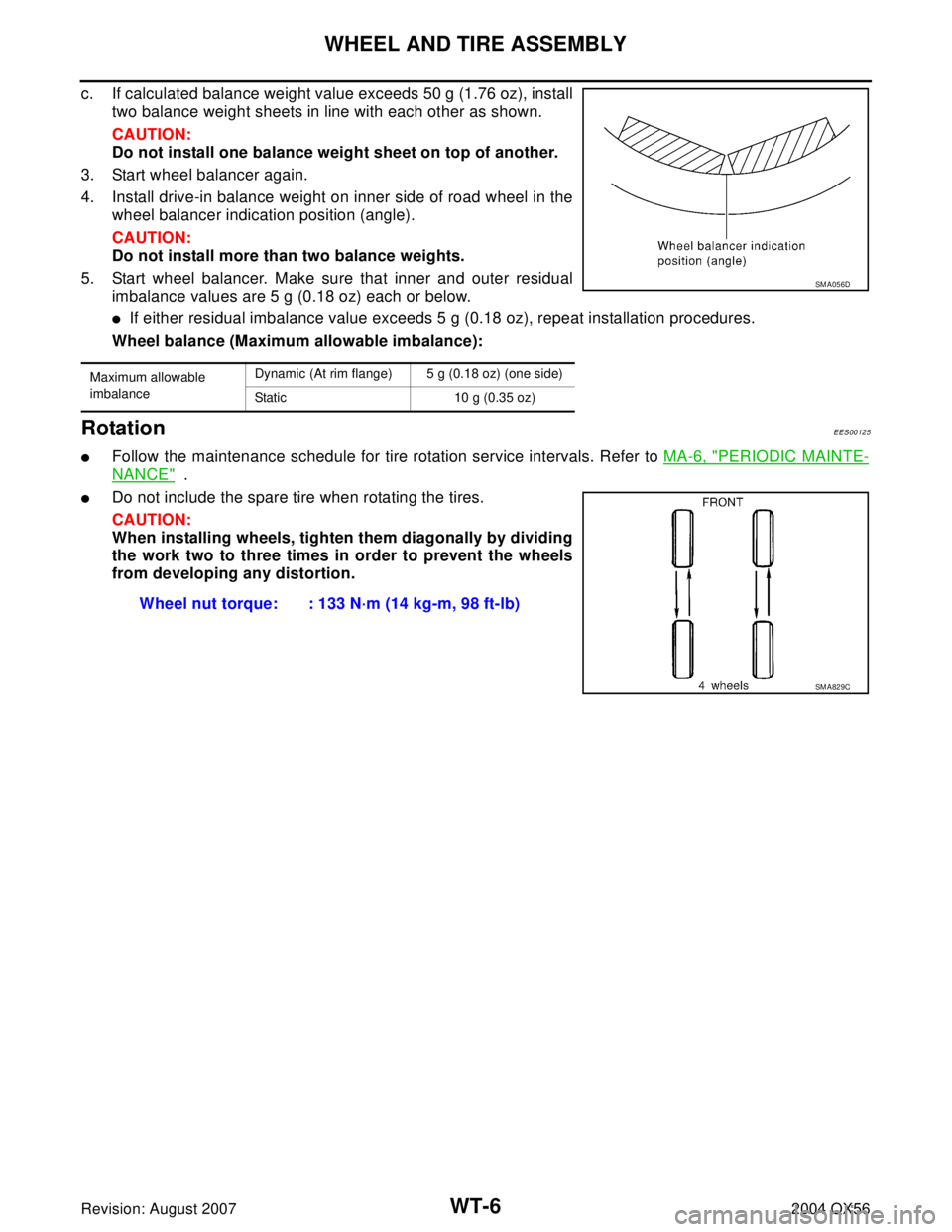
c. If calculated balance weight value exceeds 50 g (1.76 oz), install
two balance weight sheets in line with each other as shown.
CAUTION:
Do not install one balance weight sheet on top of another.
3. Start wheel balancer again.
4. Install drive-in balance weight on inner side of road wheel in the
wheel balancer indication position (angle).
CAUTION:
Do not install more than two balance weights.
5. Start wheel balancer. Make sure that inner and outer residual
imbalance values are 5 g (0.18 oz) each or below.
�If either residual imbalance value exceeds 5 g (0.18 oz), repeat installation procedures.
Wheel balance (Maximum allowable imbalance):
RotationEES00125
�Follow the maintenance schedule for tire rotation service intervals. Refer to MA-6, "PERIODIC MAINTE-
NANCE" .
�Do not include the spare tire when rotating the tires.
CAUTION:
When installing wheels, tighten them diagonally by dividing
the work two to three times in order to prevent the wheels
from developing any distortion.
Maximum allowable
imbalanceDynamic (At rim flange) 5 g (0.18 oz) (one side)
Static 10 g (0.35 oz)
SM A05 6D
Wheel nut torque: : 133 N·m (14 kg-m, 98 ft-lb)
SM A82 9C