Page 1950 of 3371
CYLINDER HEAD
EM-67
C
D
E
F
G
H
I
J
K
L
MA
EM
Revision: August 20072004 QX56
2. Remove the valve guide using suitable tool.
CAUTION:
Cylinder head contains heat. When working, wear protec-
tive equipment to avoid getting burned.
3. Ream cylinder head valve guide hole using suitable tool.
4. Heat cylinder head to 110 to 130°C (230 to 266°F) by soaking in
heated oil.
5. Press valve guide from camshaft side to dimensions as shown.
CAUTION:
Cylinder head contains heat. When working, wear protec-
tive equipment to avoid getting burned.
6. Ream cylinder head valve guide hole using suitable tool.
SEM 93 1C
Valve guide hole diameter:
Standard
Intake and exhaust : 9.975 - 9.996 mm (0.3927 -
0.3935 in)
Oversize (service)
Intake and exhaust : 10.175 - 10.196 mm
(0.4006 - 0.4014 in)
SEM 93 2C
SEM 00 8A
KBIA2530E
Valve guide hole diameter:
Intake and exhaust : 6.000 - 6.018 mm
(0.2362 - 0.2369 in)
SEM 93 2C
Page 1951 of 3371
EM-68Revision: August 2007
CYLINDER HEAD
2004 QX56
VALVE SEAT CONTACT
�After confirming that the dimensions of valve guides and valves
are within specifications, perform this procedure.
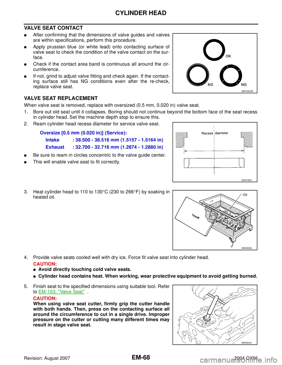
�Apply prussian blue (or white lead) onto contacting surface of
valve seat to check the condition of the valve contact on the sur-
face.
�Check if the contact area band is continuous all around the cir-
cumference.
�If not, grind to adjust valve fitting and check again. If the contact-
ing surface still has NG conditions even after the re-check,
replace valve seat.
VALVE SEAT REPLACEMENT
When valve seat is removed, replace with oversized (0.5 mm, 0.020 in) valve seat.
1. Bore out old seat until it collapses. Boring should not continue beyond the bottom face of the seat recess
in cylinder head. Set the machine depth stop to ensure this.
2. Ream cylinder head recess diameter for service valve seat.
�Be sure to ream in circles concentric to the valve guide center.
�This will enable valve seat to fit correctly.
3. Heat cylinder head to 110 to 130°C (230 to 266°F) by soaking in
heated oil.
4. Provide valve seats cooled well with dry ice. Force fit valve seat into cylinder head.
CAUTION:
�Avoid directly touching cold valve seats.
�Cylinder head contains heat. When working, wear protective equipment to avoid getting burned.
5. Finish seat to the specified dimensions using suitable tool. Refer
to EM-103, "
Valve Seat" .
CAUTION:
When using valve seat cutter, firmly grip the cutter handle
with both hands. Then, press on the contacting surface all
around the circumference to cut in a single drive. Improper
pressure on the cutter or cutting many different times may
result in stage valve seat.
SBIA0322E
Oversize [0.5 mm (0.020 in)] (Service):
Intake : 38.500 - 38.516 mm (1.5157 - 1.5164 in)
Exhaust : 32.700 - 32.716 mm (1.2874 - 1.2880 in)
SEM 79 5A
SEM 00 8A
SEM 93 4C
Page 1952 of 3371
CYLINDER HEAD
EM-69
C
D
E
F
G
H
I
J
K
L
MA
EM
Revision: August 20072004 QX56
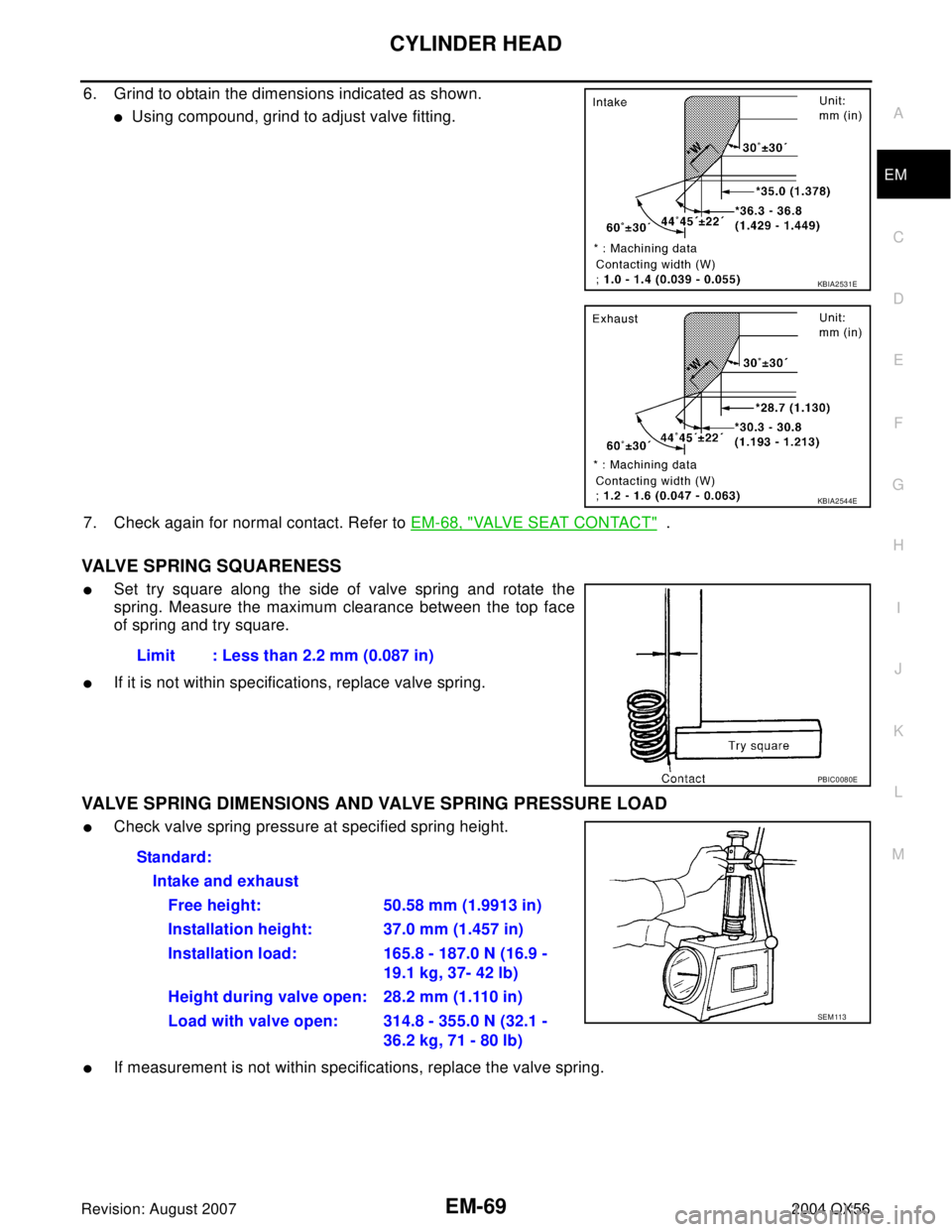
6. Grind to obtain the dimensions indicated as shown.
�Using compound, grind to adjust valve fitting.
7. Check again for normal contact. Refer to EM-68, "
VALVE SEAT CONTACT" .
VALVE SPRING SQUARENESS
�Set try square along the side of valve spring and rotate the
spring. Measure the maximum clearance between the top face
of spring and try square.
�If it is not within specifications, replace valve spring.
VALVE SPRING DIMENSIONS AND VALVE SPRING PRESSURE LOAD
�Check valve spring pressure at specified spring height.
�If measurement is not within specifications, replace the valve spring.
KBIA2531E
KBIA2544E
Limit : Less than 2.2 mm (0.087 in)
PBIC0080E
Standard:
Intake and exhaust
Free height: 50.58 mm (1.9913 in)
Installation height: 37.0 mm (1.457 in)
Installation load: 165.8 - 187.0 N (16.9 -
19.1 kg, 37- 42 lb)
Height during valve open: 28.2 mm (1.110 in)
Load with valve open: 314.8 - 355.0 N (32.1 -
36.2 kg, 71 - 80 lb)
SEM 113
Page 1967 of 3371
EM-84Revision: August 2007
CYLINDER BLOCK
2004 QX56
HOW TO SELECT CONNECTING ROD BEARING
When New Connecting Rod and Crankshaft are Used
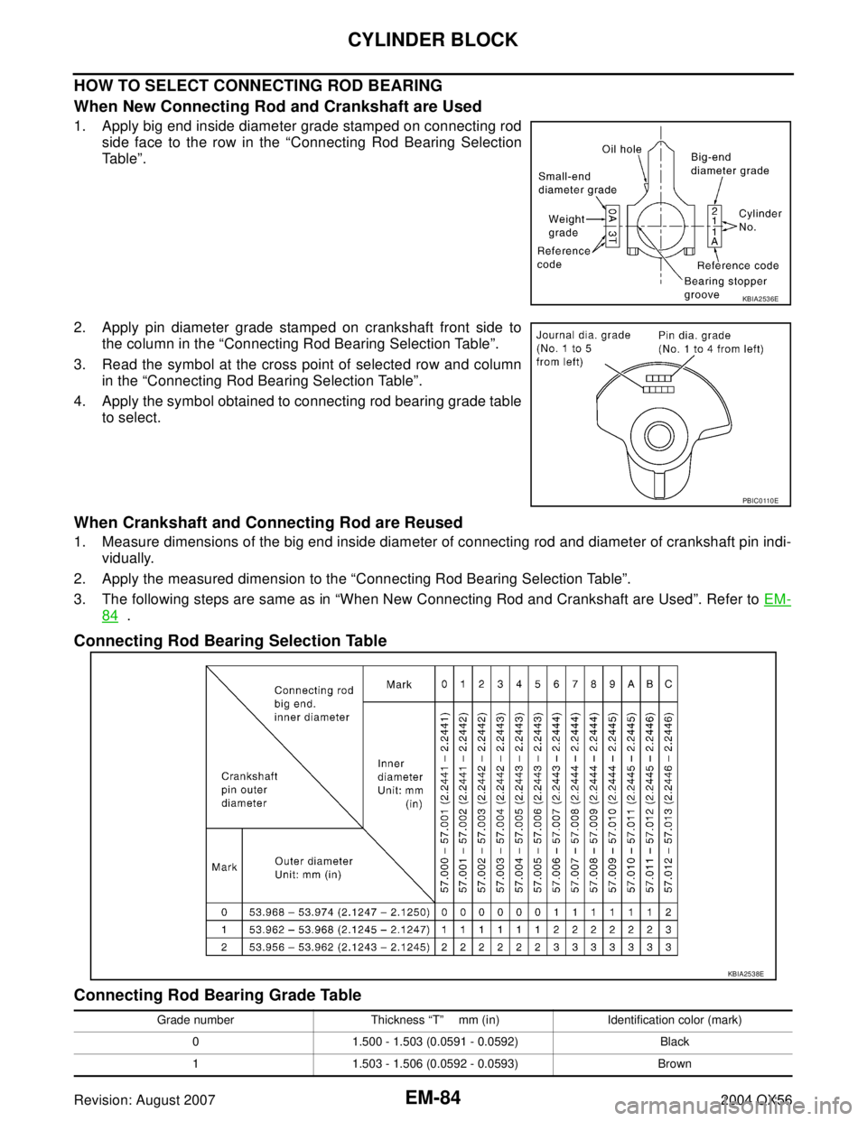
1. Apply big end inside diameter grade stamped on connecting rod
side face to the row in the “Connecting Rod Bearing Selection
Table”.
2. Apply pin diameter grade stamped on crankshaft front side to
the column in the “Connecting Rod Bearing Selection Table”.
3. Read the symbol at the cross point of selected row and column
in the “Connecting Rod Bearing Selection Table”.
4. Apply the symbol obtained to connecting rod bearing grade table
to select.
When Crankshaft and Connecting Rod are Reused
1. Measure dimensions of the big end inside diameter of connecting rod and diameter of crankshaft pin indi-
vidually.
2. Apply the measured dimension to the “Connecting Rod Bearing Selection Table”.
3. The following steps are same as in “When New Connecting Rod and Crankshaft are Used”. Refer to EM-
84 .
Connecting Rod Bearing Selection Table
Connecting Rod Bearing Grade Table
KBIA2536E
PBIC0 110 E
KBIA2538E
Grade number Thickness “T” mm (in) Identification color (mark)
0 1.500 - 1.503 (0.0591 - 0.0592) Black
1 1.503 - 1.506 (0.0592 - 0.0593) Brown
Page 1978 of 3371
CYLINDER BLOCK
EM-95
C
D
E
F
G
H
I
J
K
L
MA
EM
Revision: August 20072004 QX56
CRANKSHAFT PIN DIAMETER
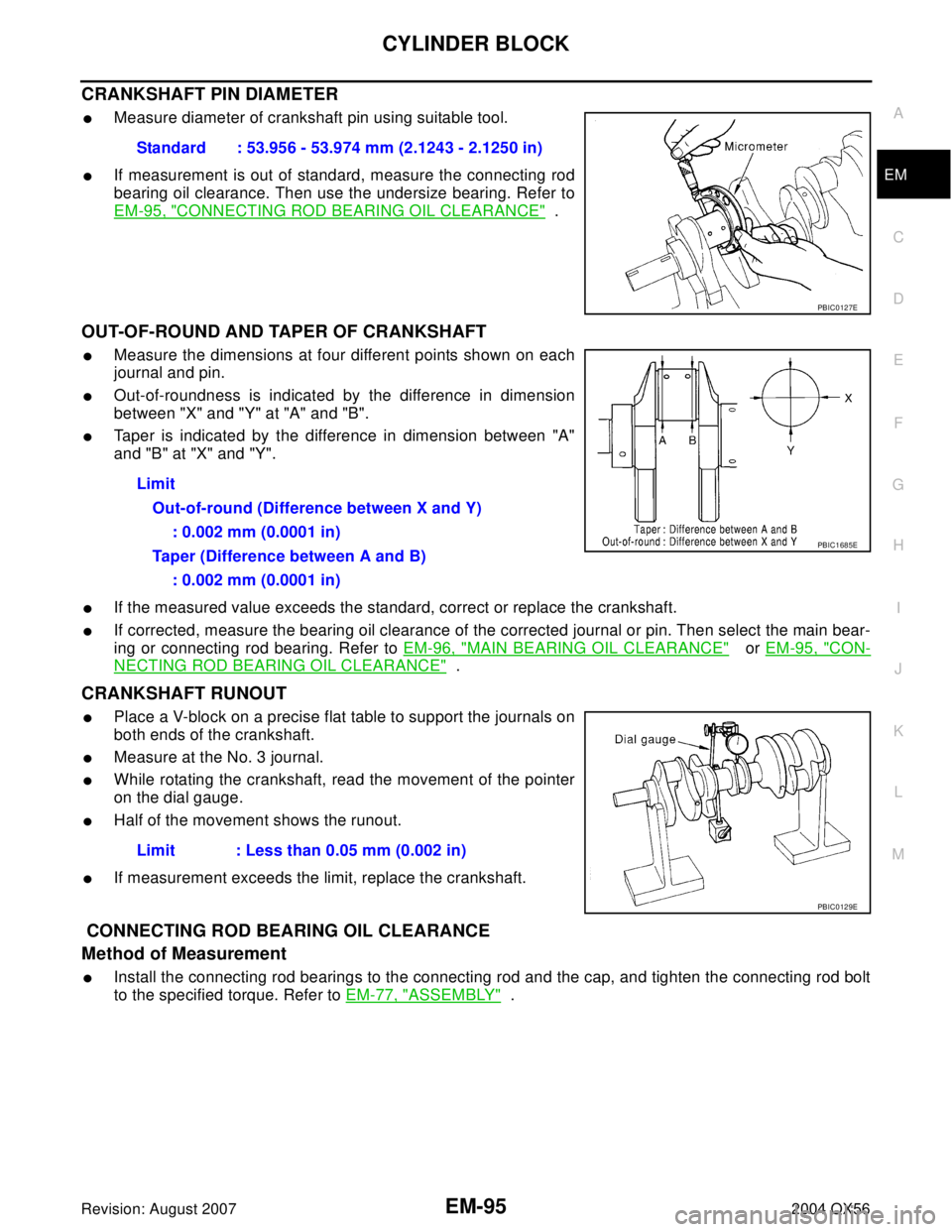
�Measure diameter of crankshaft pin using suitable tool.
�If measurement is out of standard, measure the connecting rod
bearing oil clearance. Then use the undersize bearing. Refer to
EM-95, "
CONNECTING ROD BEARING OIL CLEARANCE" .
OUT-OF-ROUND AND TAPER OF CRANKSHAFT
�Measure the dimensions at four different points shown on each
journal and pin.
�Out-of-roundness is indicated by the difference in dimension
between "X" and "Y" at "A" and "B".
�Taper is indicated by the difference in dimension between "A"
and "B" at "X" and "Y".
�If the measured value exceeds the standard, correct or replace the crankshaft.
�If corrected, measure the bearing oil clearance of the corrected journal or pin. Then select the main bear-
ing or connecting rod bearing. Refer to EM-96, "
MAIN BEARING OIL CLEARANCE" or EM-95, "CON-
NECTING ROD BEARING OIL CLEARANCE" .
CRANKSHAFT RUNOUT
�Place a V-block on a precise flat table to support the journals on
both ends of the crankshaft.
�Measure at the No. 3 journal.
�While rotating the crankshaft, read the movement of the pointer
on the dial gauge.
�Half of the movement shows the runout.
�If measurement exceeds the limit, replace the crankshaft.
CONNECTING ROD BEARING OIL CLEARANCE
Method of Measurement
�Install the connecting rod bearings to the connecting rod and the cap, and tighten the connecting rod bolt
to the specified torque. Refer to EM-77, "
ASSEMBLY" . Standard : 53.956 - 53.974 mm (2.1243 - 2.1250 in)
PBIC0127E
Limit
Out-of-round (Difference between X and Y)
: 0.002 mm (0.0001 in)
Taper (Difference between A and B)
: 0.002 mm (0.0001 in)
PBIC1685E
Limit : Less than 0.05 mm (0.002 in)
PBIC0129E
Page 1985 of 3371
EM-102Revision: August 2007
SERVICE DATA AND SPECIFICATIONS (SDS)
2004 QX56
CYLINDER HEAD
Unit: mm (in)
Valve Dimensions
Unit: mm (in) Items Standard Limit
Head surface distortion 0.03 (0.0012) 0.1 (0.004)
Nominal cylinder head height “H” 126.3 (4.97)
KBIA2554E
Valve head diameter “D”Intake 37.0 - 37.3 (1.457 - 1.469)
Exhaust 31.2 - 31.5 (1.228 - 1.240)
Valve length “L”Intake 96.21- 96.71 (3.7878 - 3.8075)
Exhaust 93.74 - 94.24 (3.6905 - 3.7102)
Valve stem diameter “d”Intake 5.965 - 5.980 (0.2348 - 0.2354)
Exhaust 5.955 - 5.970 (0.2344 - 0.2350)
Valve seat angle “α”Intake
45°15′ - 45°45′
Exhaust
Valve margin “T”Intake 1.1 (0.043)
Exhaust 1.3 (0.051)
SEM188
Page 2014 of 3371
PRECAUTIONS
FFD-3
C
E
F
G
H
I
J
K
L
MA
B
FFD
Revision: August 20072004 QX56
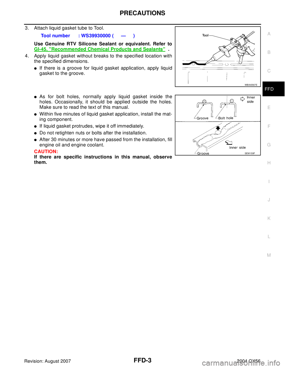
3. Attach liquid gasket tube to Tool.
Use Genuine RTV Silicone Sealant or equivalent. Refer to
GI-45, "
Recommended Chemical Products and Sealants" .
4. Apply liquid gasket without breaks to the specified location with
the specified dimensions.
�If there is a groove for liquid gasket application, apply liquid
gasket to the groove.
�As for bolt holes, normally apply liquid gasket inside the
holes. Occasionally, it should be applied outside the holes.
Make sure to read the text of this manual.
�Within five minutes of liquid gasket application, install the mat-
ing component.
�If liquid gasket protrudes, wipe it off immediately.
�Do not retighten nuts or bolts after the installation.
�After 30 minutes or more have passed from the installation, fill
engine oil and engine coolant.
CAUTION:
If there are specific instructions in this manual, observe
them.Tool number : WS39930000 ( — )
WBIA0567E
SEM 15 9F
Page 2083 of 3371
GI-2Revision: August 20072004 QX56 VEHICLE IDENTIFICATION NUMBER
ARRANGEMENT ................................................. 47
ENGINE SERIAL NUMBER ................................ 48
TRANSFER SERIAL NUMBER ........................... 48
AUTOMATIC TRANSMISSION NUMBER ........... 48Dimensions .............................................................49
Wheels & Tires ........................................................49
TERMINOLOGY ........................................................50
SAE J1930 Terminology List ...................................50