Page 3179 of 3371

TF-54
TROUBLE DIAGNOSIS — BASIC INSPECTION
Revision: August 20072004 QX56
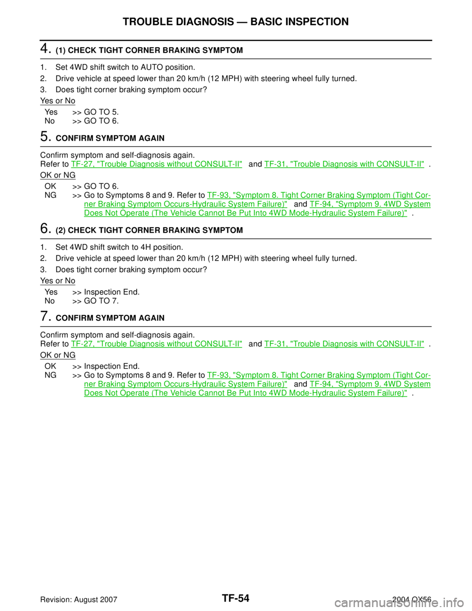
4. (1) CHECK TIGHT CORNER BRAKING SYMPTOM
1. Set 4WD shift switch to AUTO position.
2. Drive vehicle at speed lower than 20 km/h (12 MPH) with steering wheel fully turned.
3. Does tight corner braking symptom occur?
Ye s o r N o
Yes >> GO TO 5.
No >> GO TO 6.
5. CONFIRM SYMPTOM AGAIN
Confirm symptom and self-diagnosis again.
Refer to TF-27, "
Trouble Diagnosis without CONSULT-II" and TF-31, "Trouble Diagnosis with CONSULT-II" .
OK or NG
OK >> GO TO 6.
NG >> Go to Symptoms 8 and 9. Refer to TF-93, "
Symptom 8. Tight Corner Braking Symptom (Tight Cor-
ner Braking Symptom Occurs-Hydraulic System Failure)" and TF-94, "Symptom 9. 4WD System
Does Not Operate (The Vehicle Cannot Be Put Into 4WD Mode-Hydraulic System Failure)" .
6. (2) CHECK TIGHT CORNER BRAKING SYMPTOM
1. Set 4WD shift switch to 4H position.
2. Drive vehicle at speed lower than 20 km/h (12 MPH) with steering wheel fully turned.
3. Does tight corner braking symptom occur?
Ye s o r N o
Yes >> Inspection End.
No >> GO TO 7.
7. CONFIRM SYMPTOM AGAIN
Confirm symptom and self-diagnosis again.
Refer to TF-27, "
Trouble Diagnosis without CONSULT-II" and TF-31, "Trouble Diagnosis with CONSULT-II" .
OK or NG
OK >> Inspection End.
NG >> Go to Symptoms 8 and 9. Refer to TF-93, "
Symptom 8. Tight Corner Braking Symptom (Tight Cor-
ner Braking Symptom Occurs-Hydraulic System Failure)" and TF-94, "Symptom 9. 4WD System
Does Not Operate (The Vehicle Cannot Be Put Into 4WD Mode-Hydraulic System Failure)" .
Page 3180 of 3371

TROUBLE DIAGNOSIS — GENERAL DESCRIPTION
TF-55
C
E
F
G
H
I
J
K
L
MA
B
TF
Revision: August 20072004 QX56
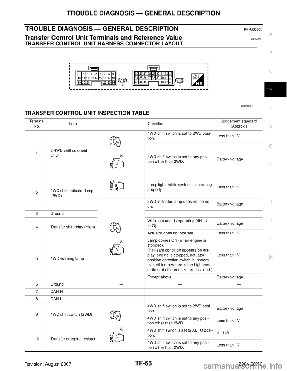
TROUBLE DIAGNOSIS — GENERAL DESCRIPTIONPFP:00000
Transfer Control Unit Terminals and Reference ValueEDS00181
TRANSFER CONTROL UNIT HARNESS CONNECTOR LAYOUT
TRANSFER CONTROL UNIT INSPECTION TABLE
LDIA0066E
Te r m i n a l
No.Item ConditionJudgement standard
(Approx.)
12-4WD shift solenoid
valve &4WD shift switch is set to 2WD posi-
tion.Less than 1V
4WD shift switch is set to any posi-
tion other than 2WD.Battery voltage
24WD shift indicator lamp
(2WD)Lamp lights while system is operating
properly.Less than 1V
&2WD indicator lamp does not come
on.Battery voltage
3Ground — —
4 Transfer shift relay (High)While actuator is operating (4H →
4LO)Battery voltage
Actuator does not operate. Less than 1V
5 4WD warning lampLamp comes ON (when engine is
stopped).
(Fail-safe condition appears on dis-
play, engine is stopped, actuator
position detection switch is inopera-
tive, oil temperature is too high and/
or tires of different size are installed.)Less than 1V
Except above Battery voltage
6Ground — — —
7CAN-H — — —
8CAN-L — — —
9 4WD shift switch (2WD)
&4WD shift switch is set to 2WD posi-
tion.Battery voltage
4WD shift switch is set to any posi-
tion other than 2WD.Less than 1V
10 Transfer dropping resistor4WD shift switch is set to AUTO posi-
tion.4 - 14V
4WD shift switch is set to any posi-
tion other than 2WD.Less than 1V
Page 3184 of 3371
DTC U1000, U1001 CAN COMMUNICATION LINE
TF-59
C
E
F
G
H
I
J
K
L
MA
B
TF
Revision: August 20072004 QX56
DTC U1000, U1001 CAN COMMUNICATION LINEPFP:23710
CAN Communication System InspectionEDS00182
INSPECTION PROCEDURE
1. PERFORM SELF-DIAGNOSIS
Perform transfer control unit self-diagnosis.
Is
“CAN COMM CIRCUIT” displayed in the self-diagnosis display items?
Yes >> Print out the self-diagnosis results and go to 2.
No >> Inspection End.
2. CONNECTOR INSPECTION
1. Disconnect the transfer control unit connectors E142 and E143.
2. Check the terminals for deformation, disconnection, looseness or damage.
OK or NG
OK >> GO TO 3.
NG >> Repair or replace as necessary.
3. CAN COMMUNICATION SYSTEM CHECK
Check the data monitor item “CAN Diagnosis Support Monitor”.
>> After printing out the monitor items, go to CAN system. Refer to LAN-3, "
Precautions When Using
CONSULT-II" .
Page 3186 of 3371
4WD SOLENOID VALVE
TF-61
C
E
F
G
H
I
J
K
L
MA
B
TF
Revision: August 20072004 QX56
4. PERFORM SELF-DIAGNOSIS
After driving for a while, perform self-diagnosis.
Refer to TF-27, "
Trouble Diagnosis without CONSULT-II" or TF-31, "Trouble Diagnosis with CONSULT-II" .
OK or NG
OK >> Inspection End.
NG >> 1. Perform transfer control unit input/output signal inspection. Refer to TF-55, "
TRANSFER CON-
TROL UNIT INSPECTION TABLE" .
2. If NG, recheck transfer control unit pin terminals for damage or loose connection with harness
connector.
Page 3187 of 3371
TF-62
2-4WD SHIFT SOLENOID VALVE AND 4WD SHIFT SWITCH
Revision: August 20072004 QX56
2-4WD SHIFT SOLENOID VALVE AND 4WD SHIFT SWITCHPFP:00000
Diagnostic ProcedureEDS00184
1. CHECK 2-4WD SHIFT SOLENOID VALVE AND 4WD SHIFT SWITCH
Refer to TF-95, "
2-4WD SHIFT SOLENOID VALVE AND TRANS-
FER FLUID TEMPERATURE SENSOR" and TF-95, "4WD SHIFT
SWITCH" .
OK or NG
OK >> GO TO 2.
NG >> Repair or replace 2-4WD shift solenoid valve or 4WD
shift switch.
2. CHECK INPUT SIGNAL
With CONSULT-II
1. Select “ECU INPUT SIGNALS” in Data Monitor.
2. Read out ON/OFF status of “2WD SW” and “LOCK SWITCH”.
OK or NG
OK >> 1. Perform transfer control unit input/output signal
inspection. Refer to TF-55, "
TRANSFER CONTROL
UNIT INSPECTION TABLE" .
2. If NG, recheck transfer control unit pin terminals for
damage or loose connection with harness connector.
NG >> GO TO 3.
SMT778D
SMT974D
Page 3188 of 3371

2-4WD SHIFT SOLENOID VALVE AND 4WD SHIFT SWITCH
TF-63
C
E
F
G
H
I
J
K
L
MA
B
TF
Revision: August 20072004 QX56
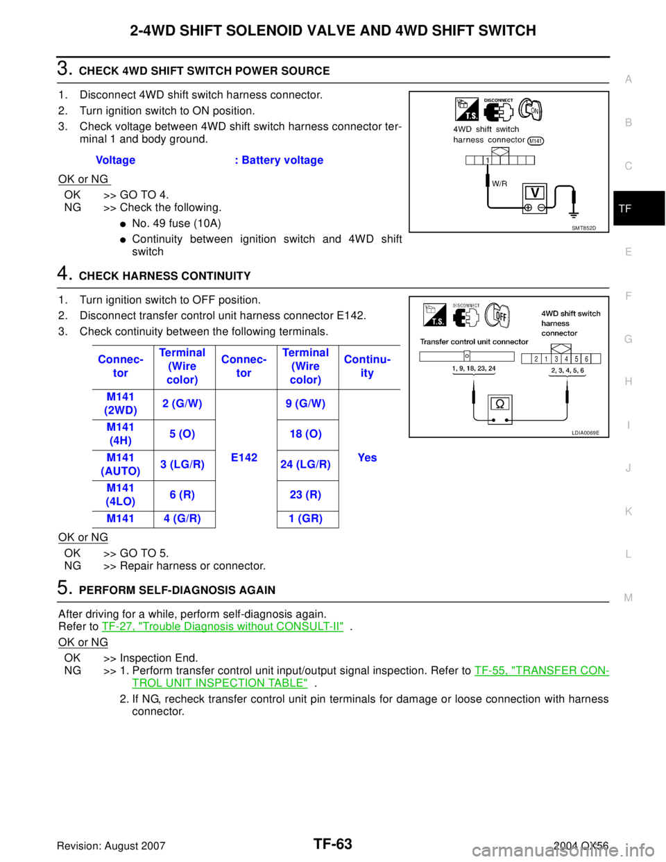
3. CHECK 4WD SHIFT SWITCH POWER SOURCE
1. Disconnect 4WD shift switch harness connector.
2. Turn ignition switch to ON position.
3. Check voltage between 4WD shift switch harness connector ter-
minal 1 and body ground.
OK or NG
OK >> GO TO 4.
NG >> Check the following.
�No. 49 fuse (10A)
�Continuity between ignition switch and 4WD shift
switch
4. CHECK HARNESS CONTINUITY
1. Turn ignition switch to OFF position.
2. Disconnect transfer control unit harness connector E142.
3. Check continuity between the following terminals.
OK or NG
OK >> GO TO 5.
NG >> Repair harness or connector.
5. PERFORM SELF-DIAGNOSIS AGAIN
After driving for a while, perform self-diagnosis again.
Refer to TF-27, "
Trouble Diagnosis without CONSULT-II" .
OK or NG
OK >> Inspection End.
NG >> 1. Perform transfer control unit input/output signal inspection. Refer to TF-55, "
TRANSFER CON-
TROL UNIT INSPECTION TABLE" .
2. If NG, recheck transfer control unit pin terminals for damage or loose connection with harness
connector. Voltage : Battery voltage
SMT852D
Connec-
torTe r m i n a l
(Wire
color)Connec-
torTe r m i na l
(Wire
color)Continu-
ity
M141
(2WD)2 (G/W)
E1429 (G/W)
Yes M141
(4H)5 (O) 18 (O)
M141
(AUTO)3 (LG/R) 24 (LG/R)
M141
(4LO)6 (R) 23 (R)
M141 4 (G/R) 1 (GR)
LDIA0069E
Page 3189 of 3371

TF-64
TRANSFER MOTOR AND TRANSFER MOTOR RELAY
Revision: August 20072004 QX56
TRANSFER MOTOR AND TRANSFER MOTOR RELAYPFP:00000
Diagnostic ProcedureEDS00185
1. CHECK TRANSFER MOTOR AND TRANSFER MOTOR RELAY
Refer to TF-96, "
TRANSFER MOTOR" and TF-97, "TRANSFER
MOTOR RELAY" .
OK or NG
OK >> GO TO 2.
NG >> Replace transfer motor or transfer motor relay.
2. CHECK INPUT SIGNAL
With CONSULT-II
1. Select “MAIN SIGNALS” in Data Monitor.
2. Read out ON/OFF status of “MOTOR RELAY”.
3. When the value is different from standard value although ON/
OFF switching occurs, check the following items.
�PNP switch and throttle position sensor circuits
Refer to AT-109, "
DTC P0705 PARK/NEUTRAL POSITION
SWITCH" , AT-129, "DTC P1705 THROTTLE POSITION SEN-
SOR" .
OK or NG
OK >> GO TO 3.
NG >> 1. Perform transfer control unit input/output signal
inspection. Refer to TF-55, "
TRANSFER CONTROL UNIT INSPECTION TABLE" .
2. If NG, recheck transfer control unit pin terminals for damage or loose connection with harness
connector.
3. CHECK TRANSFER MOTOR RELAY POWER SOURCE
1. Disconnect transfer motor relay harness connectors E153 and
E154.
2. Turn ignition switch to ON position.
3. Check voltage between transfer motor relay harness connector
E153 terminal 5 (G/R), E154 terminal 2 (Y/R), and ground.
OK or NG
OK >> GO TO 4.
NG >> Check the following.
�No. 58 fuse (20A)
�No. 49 fuse (10A)
�Harness continuity between ignition switch and No. 58 fuse (20A) and No. 49 fuse (10A).
�Harness continuity between fuse and transfer motor relay.
LDIA0102E
SMT975D
Voltage : Battery voltage
LDIA0070E
Page 3190 of 3371

TRANSFER MOTOR AND TRANSFER MOTOR RELAY
TF-65
C
E
F
G
H
I
J
K
L
MA
B
TF
Revision: August 20072004 QX56
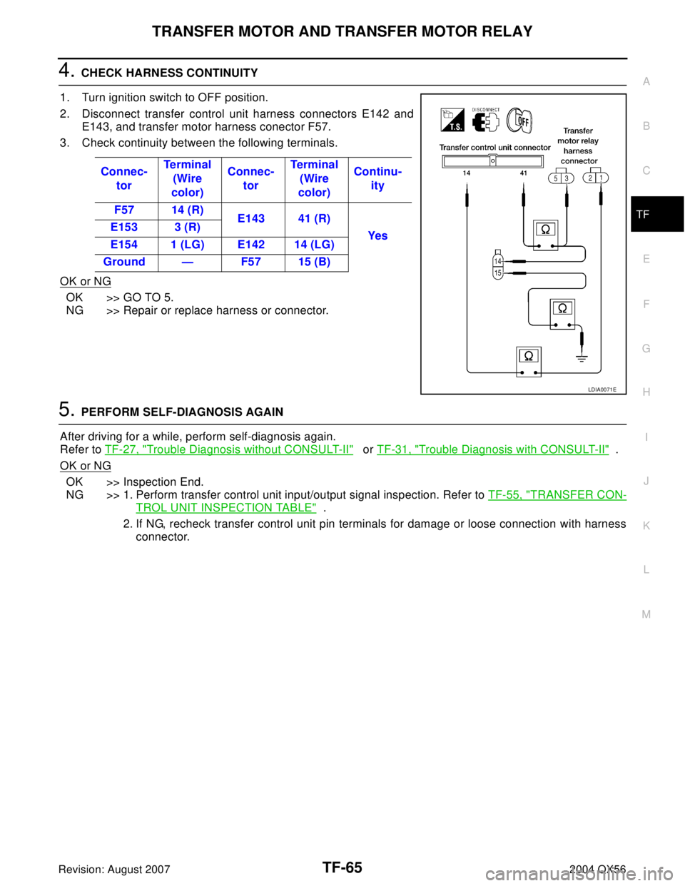
4. CHECK HARNESS CONTINUITY
1. Turn ignition switch to OFF position.
2. Disconnect transfer control unit harness connectors E142 and
E143, and transfer motor harness conector F57.
3. Check continuity between the following terminals.
OK or NG
OK >> GO TO 5.
NG >> Repair or replace harness or connector.
5. PERFORM SELF-DIAGNOSIS AGAIN
After driving for a while, perform self-diagnosis again.
Refer to TF-27, "
Trouble Diagnosis without CONSULT-II" or TF-31, "Trouble Diagnosis with CONSULT-II" .
OK or NG
OK >> Inspection End.
NG >> 1. Perform transfer control unit input/output signal inspection. Refer to TF-55, "
TRANSFER CON-
TROL UNIT INSPECTION TABLE" .
2. If NG, recheck transfer control unit pin terminals for damage or loose connection with harness
connector. Connec-
torTe r m i n a l
(Wire
color)Connec-
torTe r m i na l
(Wire
color)Continu-
ity
F57 14 (R)
E143 41 (R)
Yes E153 3 (R)
E154 1 (LG) E142 14 (LG)
Ground — F57 15 (B)
LDIA0071E