Page 3190 of 3371
TRANSFER MOTOR AND TRANSFER MOTOR RELAY
TF-65
C
E
F
G
H
I
J
K
L
MA
B
TF
Revision: August 20072004 QX56
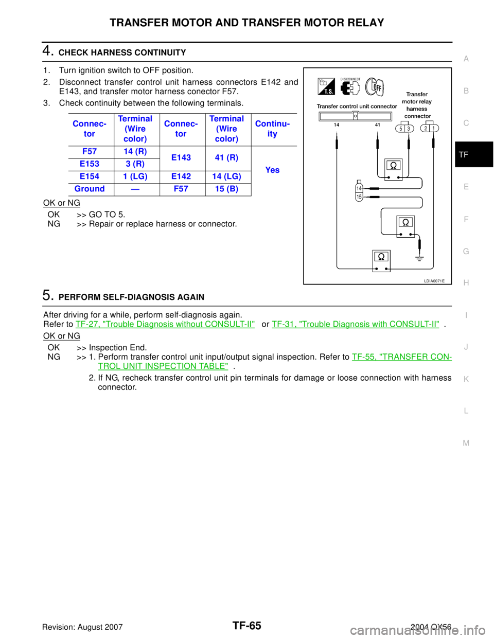
4. CHECK HARNESS CONTINUITY
1. Turn ignition switch to OFF position.
2. Disconnect transfer control unit harness connectors E142 and
E143, and transfer motor harness conector F57.
3. Check continuity between the following terminals.
OK or NG
OK >> GO TO 5.
NG >> Repair or replace harness or connector.
5. PERFORM SELF-DIAGNOSIS AGAIN
After driving for a while, perform self-diagnosis again.
Refer to TF-27, "
Trouble Diagnosis without CONSULT-II" or TF-31, "Trouble Diagnosis with CONSULT-II" .
OK or NG
OK >> Inspection End.
NG >> 1. Perform transfer control unit input/output signal inspection. Refer to TF-55, "
TRANSFER CON-
TROL UNIT INSPECTION TABLE" .
2. If NG, recheck transfer control unit pin terminals for damage or loose connection with harness
connector. Connec-
torTe r m i n a l
(Wire
color)Connec-
torTe r m i na l
(Wire
color)Continu-
ity
F57 14 (R)
E143 41 (R)
Yes E153 3 (R)
E154 1 (LG) E142 14 (LG)
Ground — F57 15 (B)
LDIA0071E
Page 3193 of 3371
TF-68
TRANSFER FLUID TEMPERATURE SENSOR
Revision: August 20072004 QX56
4. CHECK INPUT SIGNAL
Without CONSULT-II
1. Turn ignition switch to ON position.
2. Check voltage between transfer control unit harness connector
E143 terminals 28 (B/G) and 31(G).
OK or NG
OK >> GO TO 5.
NG >> Check the following.
�Continuity between transfer control unit and transfer
terminal cord assembly harness connector
5. PERFORM SELF-DIAGNOSIS AGAIN
After driving for a while, perform self-diagnosis again.
Refer to TF-27, "
Trouble Diagnosis without CONSULT-II" .
OK or NG
OK >> Inspection End.
NG >> 1. Perform transfer control unit input/output signal inspection. Refer to TF-55, "
TRANSFER CON-
TROL UNIT INSPECTION TABLE" .
2. If NG, recheck transfer control unit pin terminals for damage or loose connection with harness
connector.Vo l ta g e
20°C (68°F) : Approx. 1.1V
80°C (176°F) : Approx. 0.3V
LDIA0072E
Page 3195 of 3371
TF-70
ATP SWITCH, WAIT DETECTION SWITCH AND NEUTRAL-4LO SWITCH
Revision: August 20072004 QX56
4. CHECK HARNESS GROUND CONTINUITY
Without CONSULT-II
1. Turn ignition switch to OFF position.
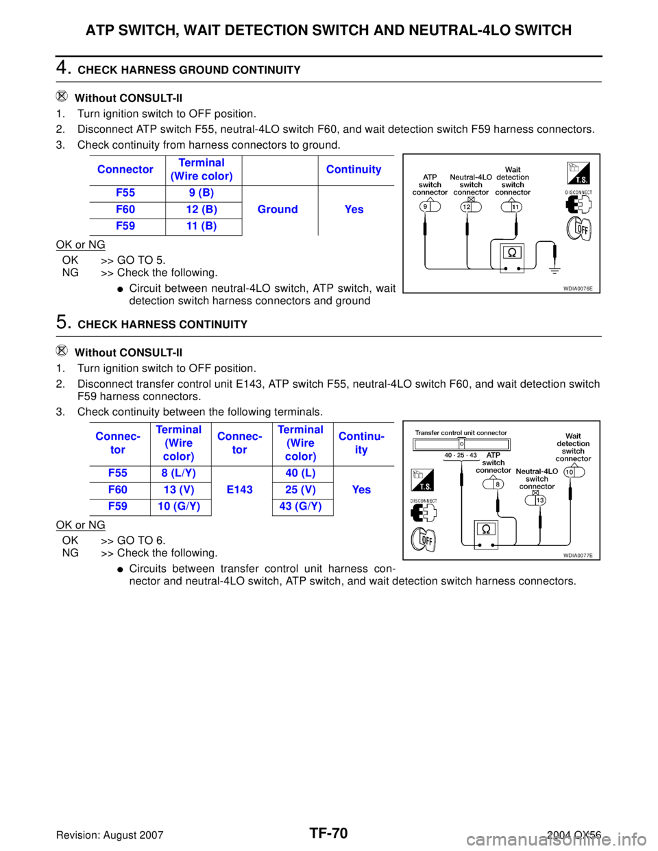
2. Disconnect ATP switch F55, neutral-4LO switch F60, and wait detection switch F59 harness connectors.
3. Check continuity from harness connectors to ground.
OK or NG
OK >> GO TO 5.
NG >> Check the following.
�Circuit between neutral-4LO switch, ATP switch, wait
detection switch harness connectors and ground
5. CHECK HARNESS CONTINUITY
Without CONSULT-II
1. Turn ignition switch to OFF position.
2. Disconnect transfer control unit E143, ATP switch F55, neutral-4LO switch F60, and wait detection switch
F59 harness connectors.
3. Check continuity between the following terminals.
OK or NG
OK >> GO TO 6.
NG >> Check the following.
�Circuits between transfer control unit harness con-
nector and neutral-4LO switch, ATP switch, and wait detection switch harness connectors. ConnectorTe r m i na l
(Wire color)Continuity
F55 9 (B)
Ground Yes F60 12 (B)
F59 11 (B)
WDIA0076E
Connec-
torTe r m i n a l
(Wire
color)Connec-
torTe r m i n a l
(Wire
color)Continu-
ity
F55 8 (L/Y)
E14340 (L)
Ye s F60 13 (V) 25 (V)
F59 10 (G/Y) 43 (G/Y)
WDIA0077E
Page 3196 of 3371
ATP SWITCH, WAIT DETECTION SWITCH AND NEUTRAL-4LO SWITCH
TF-71
C
E
F
G
H
I
J
K
L
MA
B
TF
Revision: August 20072004 QX56
6. CHECK SWITCH POWER SOURCE
Without CONSULT-II
1. Turn ignition switch to ON position.
2. Disconnect ATP switch F55, neutral-4LO switch F60, and wait detection switch F59 harness connectors.
3. Check voltage between the following terminals.
OK or NG
OK >> Inspection End.
NG >> GO TO 7.
7. PERFORM SELF-DIAGNOSIS AGAIN
After driving for a while, perform self-diagnosis again.
Refer to TF-27, "
Trouble Diagnosis without CONSULT-II" .
OK or NG
OK >> Inspection End.
NG >> 1. Perform transfer control unit input/output signal inspection. Refer to TF-55, "
TRANSFER CON-
TROL UNIT INSPECTION TABLE" .
2. If NG, recheck transfer control unit pin terminals for damage or loose connection with harness
connector. ConnectorTe r m i n a l
(Wire color)Battery
voltage
E14340 (L)
Ground Yes 25 (V)
43 (G/Y)
WDIA0059E
Page 3198 of 3371
CLUTCH PRESSURE SWITCH
TF-73
C
E
F
G
H
I
J
K
L
MA
B
TF
Revision: August 20072004 QX56
5. CHECK INPUT SIGNAL
With CONSULT-II
1. Turn ignition switch to ON position.
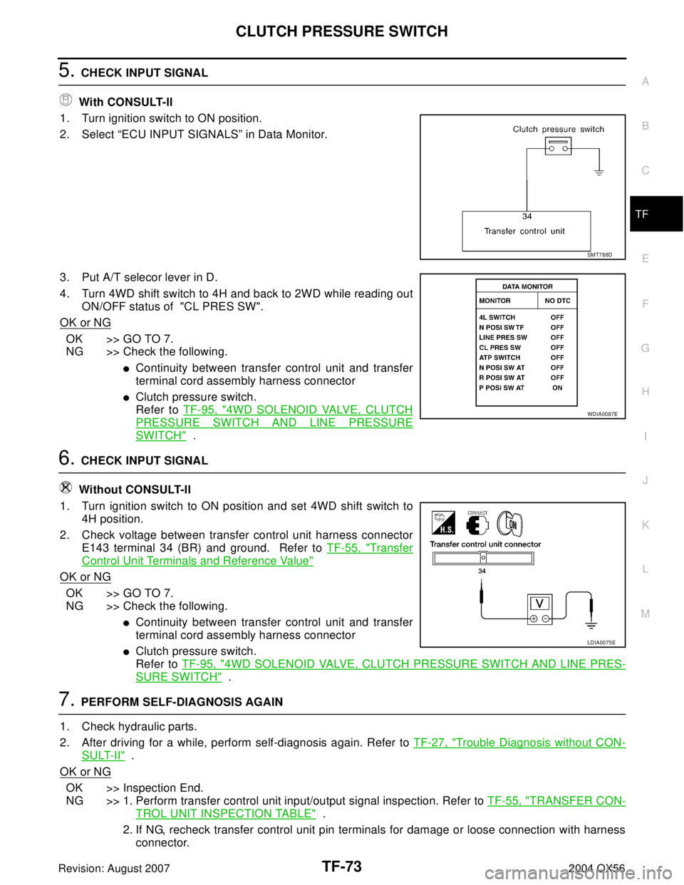
2. Select “ECU INPUT SIGNALS” in Data Monitor.
3. Put A/T selecor lever in D.
4. Turn 4WD shift switch to 4H and back to 2WD while reading out
ON/OFF status of "CL PRES SW".
OK or NG
OK >> GO TO 7.
NG >> Check the following.
�Continuity between transfer control unit and transfer
terminal cord assembly harness connector
�Clutch pressure switch.
Refer to TF-95, "
4WD SOLENOID VALVE, CLUTCH
PRESSURE SWITCH AND LINE PRESSURE
SWITCH" .
6. CHECK INPUT SIGNAL
Without CONSULT-II
1. Turn ignition switch to ON position and set 4WD shift switch to
4H position.
2. Check voltage between transfer control unit harness connector
E143 terminal 34 (BR) and ground. Refer to TF-55, "
Transfer
Control Unit Terminals and Reference Value"
OK or NG
OK >> GO TO 7.
NG >> Check the following.
�Continuity between transfer control unit and transfer
terminal cord assembly harness connector
�Clutch pressure switch.
Refer to TF-95, "
4WD SOLENOID VALVE, CLUTCH PRESSURE SWITCH AND LINE PRES-
SURE SWITCH" .
7. PERFORM SELF-DIAGNOSIS AGAIN
1. Check hydraulic parts.
2. After driving for a while, perform self-diagnosis again. Refer to TF-27, "
Trouble Diagnosis without CON-
SULT-II" .
OK or NG
OK >> Inspection End.
NG >> 1. Perform transfer control unit input/output signal inspection. Refer to TF-55, "
TRANSFER CON-
TROL UNIT INSPECTION TABLE" .
2. If NG, recheck transfer control unit pin terminals for damage or loose connection with harness
connector.
SMT788D
WDIA0087E
LDIA0075E
Page 3200 of 3371
LINE PRESSURE SWITCH
TF-75
C
E
F
G
H
I
J
K
L
MA
B
TF
Revision: August 20072004 QX56
5. CHECK INPUT SIGNAL
Without CONSULT-II
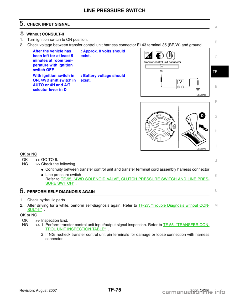
1. Turn ignition switch to ON position.
2. Check voltage between transfer control unit harness connector E143 terminal 35 (BR/W) and ground.
OK or NG
OK >> GO TO 6.
NG >> Check the following.
�Continuity between transfer control unit and transfer terminal cord assembly harness connector
�Line pressure switch
Refer to TF-95, "
4WD SOLENOID VALVE, CLUTCH PRESSURE SWITCH AND LINE PRES-
SURE SWITCH" .
6. PERFORM SELF-DIAGNOSIS AGAIN
1. Check hydraulic parts.
2. After driving for a while, perform self-diagnosis again. Refer to TF-27, "
Trouble Diagnosis without CON-
SULT-II" .
OK or NG
OK >> Inspection End.
NG >> 1. Perform transfer control unit input/output signal inspection. Refer to TF-55, "
TRANSFER CON-
TROL UNIT INSPECTION TABLE" .
2. If NG, recheck transfer control unit pin terminals for damage or loose connection with harness
connector. After the vehicle has
been left for at least 5
minutes at room tem-
perature with ignition
switch OFF: Approx. 0 volts should
exist.
With ignition switch in
ON, 4WD shift switch in
AUTO or 4H and A/T
selector lever in D: Battery voltage should
exist.
LDIA0076E
LDIA0077E
Page 3201 of 3371
TF-76
DATA ERASE/DISPLAY
Revision: August 20072004 QX56
DATA ERASE/DISPLAYPFP:00000
Diagnostic ProcedureEDS0018A
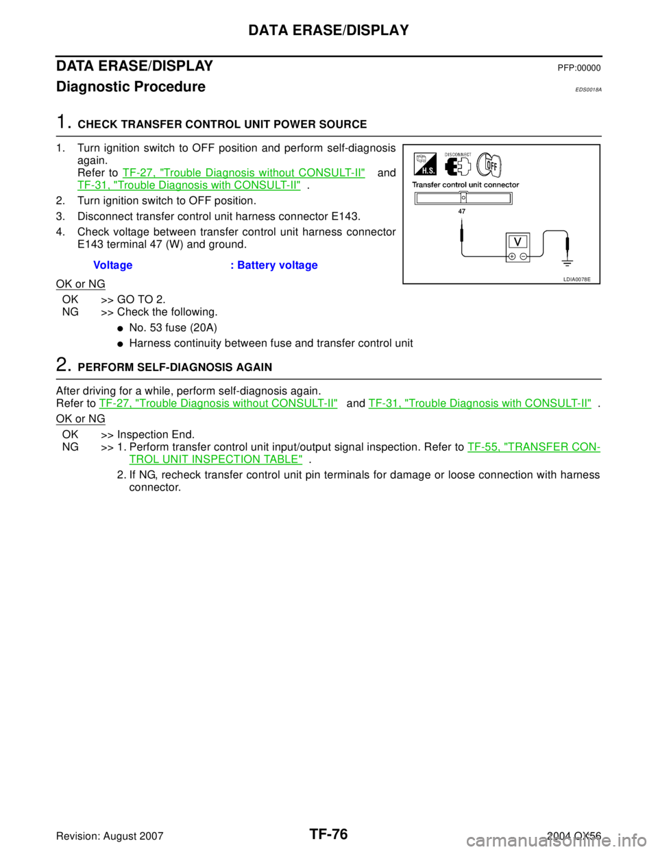
1. CHECK TRANSFER CONTROL UNIT POWER SOURCE
1. Turn ignition switch to OFF position and perform self-diagnosis
again.
Refer to TF-27, "
Trouble Diagnosis without CONSULT-II" and
TF-31, "
Trouble Diagnosis with CONSULT-II" .
2. Turn ignition switch to OFF position.
3. Disconnect transfer control unit harness connector E143.
4. Check voltage between transfer control unit harness connector
E143 terminal 47 (W) and ground.
OK or NG
OK >> GO TO 2.
NG >> Check the following.
�No. 53 fuse (20A)
�Harness continuity between fuse and transfer control unit
2. PERFORM SELF-DIAGNOSIS AGAIN
After driving for a while, perform self-diagnosis again.
Refer to TF-27, "
Trouble Diagnosis without CONSULT-II" and TF-31, "Trouble Diagnosis with CONSULT-II" .
OK or NG
OK >> Inspection End.
NG >> 1. Perform transfer control unit input/output signal inspection. Refer to TF-55, "
TRANSFER CON-
TROL UNIT INSPECTION TABLE" .
2. If NG, recheck transfer control unit pin terminals for damage or loose connection with harness
connector. Voltage : Battery voltage
LDIA0078E
Page 3202 of 3371
SHIFT ACTUATOR
TF-77
C
E
F
G
H
I
J
K
L
MA
B
TF
Revision: August 20072004 QX56
SHIFT ACTUATORPFP:00000
Diagnostic ProcedureEDS0018B
1. SHIFT ACTUATOR
Refer to TF-97, "
ACTUATOR AND ACTUATOR POSITION SWITCH" .
OK or NG
OK >> GO TO 3.
NG >> GO TO 2.
2. CHECK POWER SOURCE
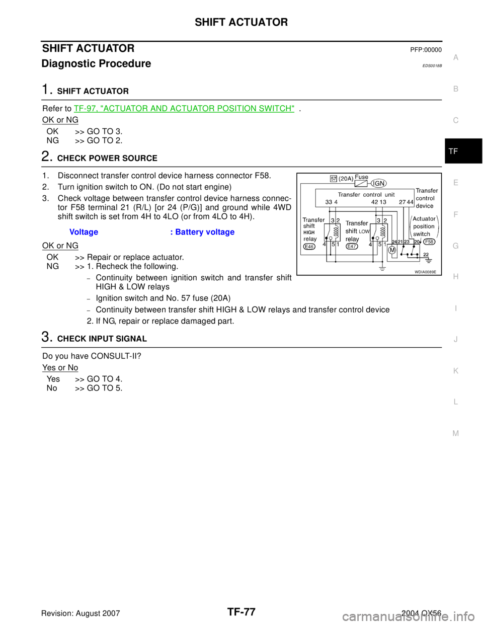
1. Disconnect transfer control device harness connector F58.
2. Turn ignition switch to ON. (Do not start engine)
3. Check voltage between transfer control device harness connec-
tor F58 terminal 21 (R/L) [or 24 (P/G)] and ground while 4WD
shift switch is set from 4H to 4LO (or from 4LO to 4H).
OK or NG
OK >> Repair or replace actuator.
NG >> 1. Recheck the following.
–Continuity between ignition switch and transfer shift
HIGH & LOW relays
–Ignition switch and No. 57 fuse (20A)
–Continuity between transfer shift HIGH & LOW relays and transfer control device
2. If NG, repair or replace damaged part.
3. CHECK INPUT SIGNAL
Do you have CONSULT-II?
Ye s o r N o
Yes >> GO TO 4.
No >> GO TO 5.Voltage : Battery voltage
WDIA0089E