Page 1901 of 3371
EM-18Revision: August 2007
INTAKE MANIFOLD
2004 QX56
5. Install the quick connector cap on the quick connector joint (on
engine side only).
6. Install the fuel hose and tube to hose clamps.
7. Refill the engine coolant. Refer to MA-13, "
REFILLING ENGINE
COOLANT" .
INSPECTION AFTER INSTALLATION
�After installing fuel tubes, make sure there is no fuel leakage at connections in the following steps.
–Apply fuel pressure to fuel lines with turning ignition switch ON (with engine stopped). Then check for
fuel leaks at connections.
–Start the engine and rev it up and check for fuel leaks at connections.
�Perform procedures for “Throttle Valve Closed Position Learning” after finishing repairs. Refer to EC-44,
"Throttle Valve Closed Position Learning" .
�If electric throttle control actuator is replaced, perform procedures for “Idle Air Volume Learning” after fin-
ishing repairs. Refer to EC-44, "
Idle Air Volume Learning" .
SBIA0354E
Page 1902 of 3371

EXHAUST MANIFOLD AND THREE WAY CATALYST
EM-19
C
D
E
F
G
H
I
J
K
L
MA
EM
Revision: August 20072004 QX56
EXHAUST MANIFOLD AND THREE WAY CATALYSTPFP:14004
Removal and InstallationEBS00ILG
REMOVAL
WA RN ING:
Perform the work when the exhaust and cooling system have cooled sufficiently.
1. Remove air duct and resonator assembly. Refer to EM-14, "
REMOVAL" .
2. Drain engine coolant from the radiator. Refer to MA-12, "
DRAINING ENGINE COOLANT" .
3. Remove engine undercover using power tool.
4. Remove the radiator and radiator hoses. Refer to CO-10, "
RADIATOR" .
5. Remove the drive belts. Refer to EM-12, "
Removal" .
6. Remove the air fuel ratio A/F sensors (right bank, left bank), using the following steps.
a. Remove engine room cover using power tool. Refer to EM-11, "
REMOVAL" .
b. Remove harness connector of each air fuel ratio A/F sensors, and harness from bracket and middle
clamp.
1. Air fuel ratio (A/F) sensor 1 (bank 2) 2. Exhaust manifold cover (bank 2) 3. Exhaust manifold (bank 2)
4. Gaskets 5. Exhaust manifold (left bank 1) 6. Exhaust manifold cover (bank 1)
7. Air fuel ratio (A/F) sensor 1 (bank 1)
WBIA0466E
Page 1903 of 3371

EM-20Revision: August 2007
EXHAUST MANIFOLD AND THREE WAY CATALYST
2004 QX56
c. Remove the air fuel ratio A/F sensors from both left and right
exhaust manifolds using Tool.
CAUTION:
�Be careful not to damage the air fuel ratio A/F sensors
�Discard any air fuel ratio A/F sensor which has been
dropped from a height of more than 0.5m (19.7 in) onto a
hard surface such as a concrete floor. Replace it with a
new one.
7. Remove the front cross bar.
8. Remove the exhaust manifold (left bank) using the following
steps.
a. Remove the exhaust front tube using power tool. Refer to EX-3,
"Removal and Installation" .
b. Remove the exhaust manifold cover.
c. Loosen the nuts in reverse order shown using power tool.
d. Remove the exhaust studs from positions 2, 4, 6, 8 and remove
the left exhaust manifold.
9. Remove the exhaust manifold (right bank) using the following
steps.
a. Remove the exhaust front tube using power tool. Refer to EX-3,
"Removal and Installation" .
b. Remove the oil level gauge guide. Refer to EM-22, "
OIL PAN
AND OIL STRAINER" .
c. Remove the exhaust manifold cover.
d. Loosen the nuts in reverse order shown using power tool.
e. Remove the exhaust studs from positions 2, 4, 6, 8 and remove the right exhaust manifold.
INSPECTION AFTER REMOVAL
Surface Distortion
�Use a reliable straightedge and feeler gauge to check the flat-
ness of each exhaust manifold flange surface.
�If flatness exceeds the limit, replace the exhaust manifold.
INSTALLATION
Installation is in the reverse order of removal.
�Install a new exhaust manifold gasket with the top of the triangu-
lar up mark on it facing up and its coated face (gray side) toward
the exhaust manifold side.Tool number : — (J-44626)
WBIA0630E
KBIA2464E
Flatness limit : 0.3 mm (0.012 in)
KBIA2504E
KBIA2553E
Page 1904 of 3371
EXHAUST MANIFOLD AND THREE WAY CATALYST
EM-21
C
D
E
F
G
H
I
J
K
L
MA
EM
Revision: August 20072004 QX56
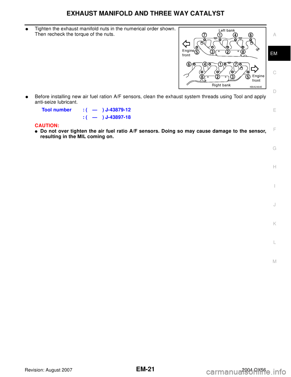
�Tighten the exhaust manifold nuts in the numerical order shown.
Then recheck the torque of the nuts.
�Before installing new air fuel ration A/F sensors, clean the exhaust system threads using Tool and apply
anti-seize lubricant.
CAUTION:
�Do not over tighten the air fuel ratio A/F sensors. Doing so may cause damage to the sensor,
resulting in the MIL coming on.
KBIA2464E
Tool number : ( — ) J-43879-12
: ( — ) J-43897-18
Page 1911 of 3371
EM-28Revision: August 2007
SPARK PLUG (PLATINUM-TIPPED TYPE)
2004 QX56
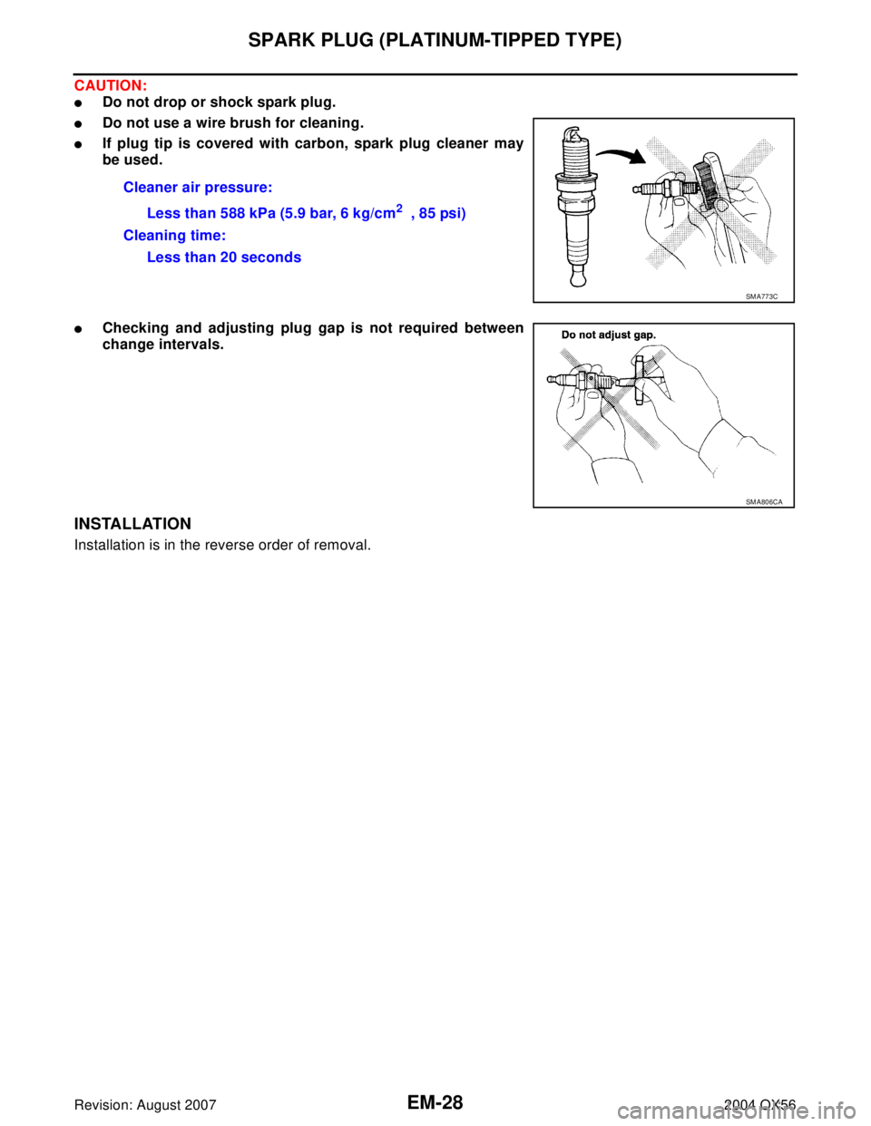
CAUTION:
�Do not drop or shock spark plug.
�Do not use a wire brush for cleaning.
�If plug tip is covered with carbon, spark plug cleaner may
be used.
�Checking and adjusting plug gap is not required between
change intervals.
INSTALLATION
Installation is in the reverse order of removal.Cleaner air pressure:
Less than 588 kPa (5.9 bar, 6 kg/cm
2 , 85 psi)
Cleaning time:
Less than 20 seconds
SM A77 3C
SM A80 6CA
Page 1916 of 3371
ROCKER COVER
EM-33
C
D
E
F
G
H
I
J
K
L
MA
EM
Revision: August 20072004 QX56
ROCKER COVERPFP:13264
Removal and InstallationEBS00ILL
REMOVAL
1. Remove the engine room cover using power tool. Refer to EM-11, "REMOVAL" .
2. Remove the air duct and resonator assembly. Refer to EM-14, "
REMOVAL" (for left bank only) .
3. Move the harness on the upper rocker cover and its peripheral aside.
4. Remove the electric throttle control actuator, loosening bolts diagonally (for left bank only).
5. Remove the ignition coil. Refer to EM-26, "
REMOVAL" .
6. Remove the PCV hose from the PCV control valve.
7. Loosen the bolts in reverse order shown using power tool.
CAUTION:
Do not hold the rocker cover by the oil filler neck (right
bank).
1. Rocker cover (left bank) 2. PCV control valve 3. O-ring
4. Rocker cover gasket (left bank) 5. Rocker cover (right bank) 6. PCV control valve
7. O-ring 8. Oil filler cap 9. Rocker cover gasket (right bank)
KBIA2508E
KBIA2509E
Page 1917 of 3371

EM-34Revision: August 2007
ROCKER COVER
2004 QX56
INSTALLATION
1. Apply liquid gasket to the joint part of the cylinder head and
camshaft bracket following the steps below.
NOTE:
Illustration shows an example of left bank side (zoomed in
shows No.1 camshaft bracket).
a. Refer to illustration “a” to apply liquid gasket to the joint part of
No.1 camshaft bracket and cylinder head.
b. Refer to illustration “b” to apply liquid gasket 90° to illustration
“a”.
Use Genuine RTV Silicone Sealant or equivalent. Refer to
GI-45, "
Recommended Chemical Products and Sealants" .
2. Install the rocker cover.
�Make sure the new rocker cover gasket is installed in the groove of the rocker cover.
�Tighten bolts in two steps separately in the numerical order
shown.
CAUTION:
Do not hold the rocker cover by the oil filler neck (right
bank).
3. Install the PCV hose using the following procedure.
�Remove any foreign materials from inside the hose with com-
pressed air.
�Insert the hose within 25 - 30 mm (0.98 - 1.18 in) [Target: 25 mm (0.98 in)].
4. Installation of the remaining components is in the reverse order of removal.
KBIA2510E
1st step : 2.0 N·m (0.2 kg-m, 18 in-lb)
2nd step : 8.3 N·m (0.85 kg-m, 73 in-lb)
KBIA2509E
Page 1935 of 3371

EM-52Revision: August 2007
CAMSHAFT
2004 QX56
�Install intake and exhaust side camshaft sprocket by selec-
tively using the groove of dowel pin according to the bank.
(Common part used for both banks.)
b. Lock the hexagonal part of camshaft in the same way as for
removal, and tighten bolts.
c. Check again that the timing mating mark on timing chain and on
each sprocket are aligned.
6. Install chain tensioner with the following procedure:
NOTE:
Left bank is shown.
a. Install chain tensioner.
�Compress plunger and hold it with a stopper pin when install-
ing.
�Loosen the slack guide side timing chain by rotating camshaft
hexagonal part if mounting space is small.
b. Remove stopper pin and release plunger, and then apply ten-
sion to timing chain.
c. Install chain tensioner cover onto front cover. (RH bank)
�Apply liquid gasket as shown.
Use Genuine RTV Silicone Sealant or equivalent. Refer to
GI-45, "
Recommended Chemical Products and Seal-
ants" .
7. Check and adjust valve clearances. Refer to EM-52, "
Va l v e
Clearance" .
8. Installation of the remaining components is in the reverse order
of removal.
Va lv e C le a ra n c eEBS00ILO
INSPECTION
NOTE:
Perform inspection as follows after removal, installation or replacement of camshaft or valve-related parts, or if
there are unusual engine conditions due to changes in valve clearance over time (starting, idling, and/or
noise).
1. Warm up engine. Then stop engine.
2. Remove engine cover, battery cover and air duct. Refer to EM-11, "
Removal and Installation" , SC-9,
"REMOVAL" and EM-14, "Removal and Installation" .
3. Remove right bank and left bank rocker covers using power tool. Refer to EM-33, "
Removal and Installa-
tion" .
KBIA2480E
Chain tensioner bolts : 6.9 N·m (0.70 kg-m, 61 in-lb)
Tensioner cover bolts : 9.0 N·m (0.92 kg-m, 80 in-lb)KBIA2479E
KBIA2547E
.
6. Install the fuel hose and tube to hose clamps.
7. Refill")