Page 308 of 4449

TROUBLE DIAGNOSIS FOR SYMPTOMS
AT-231
D
E
F
G
H
I
J
K
L
MA
B
AT
Revision: 2004 November 2004 FX35/FX45
Vehicle Does Not Decelerate By Engine BrakeACS007GY
SYMPTOM:
No engine brake is applied when the gear is shifted from the 2nd to 1st gear.
DIAGNOSTIC PROCEDURE
1. CHECK SELF-DIAGNOSTIC RESULTS
Perform self-diagnosis. Refer to AT- 9 4 , "
SELF-DIAGNOSTIC RESULT MODE" .
Do the self-diagnostic results indicate PNP switch, ATF pressure switch 5?
YES >> Check the malfunctioning system. Refer to AT- 11 2 , "DTC P0705 PARK/NEUTRAL POSITION
SWITCH" , AT- 1 8 2 , "DTC P1845 ATF PRESSURE SWITCH 5" .
NO >> GO TO 2.
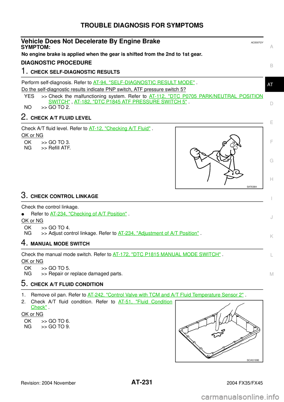
2. CHECK A/T FLUID LEVEL
Check A/T fluid level. Refer to AT- 1 2 , "
Checking A/T Fluid" .
OK or NG
OK >> GO TO 3.
NG >> Refill ATF.
3. CHECK CONTROL LINKAGE
Check the control linkage.
�Refer to AT- 2 3 4 , "Checking of A/T Position" .
OK or NG
OK >> GO TO 4.
NG >> Adjust control linkage. Refer to AT- 2 3 4 , "
Adjustment of A/T Position" .
4. MANUAL MODE SWITCH
Check the manual mode switch. Refer to AT- 1 7 2 , "
DTC P1815 MANUAL MODE SWITCH" .
OK or NG
OK >> GO TO 5.
NG >> Repair or replace damaged parts.
5. CHECK A/T FLUID CONDITION
1. Remove oil pan. Refer to AT- 2 4 2 , "
Control Valve with TCM and A/T Fluid Temperature Sensor 2" .
2. Check A/T fluid condition. Refer to AT- 5 1 , "
Fluid Condition
Check" .
OK or NG
OK >> GO TO 6.
NG >> GO TO 9.
SAT638A
SCIA5199E
Page 374 of 4449

DISASSEMBLY
AT-297
D
E
F
G
H
I
J
K
L
MA
B
AT
Revision: 2004 November 2004 FX35/FX45
45. Remove needle bearing from transmission case.
46. Remove revolution sensor from transmission case.
CAUTION:
�Do not subject it to impact by dropping or hitting it.
�Do not disassemble.
�Do not allow metal filings, etc., to get on the sensor's
front edge magnetic area.
�Do not place in an area affected by magnetism.
47. Remove reverse brake snap ring (fixing plate) using 2 flat-
bladed screwdrivers.
NOTE:
Press out snap ring from the transmission case oil pan side gap
using a flat-bladed screwdriver, and remove it using another
screwdriver.
48. Remove reverse brake retaining plate from transmission case.
�Check facing for burns, cracks or damage. If necessary,
replace the plate.
49. Remove N-spring from transmission case.
50. Remove reverse brake drive plates, driven plates and dish plate
from transmission case.
�Check facing for burns, cracks or damage. If necessary,
replace the plate.
SCIA5031E
SCIA2320E
SCIA5032E
SCIA5214E
SCIA2322E
Page 407 of 4449
AT-330
ASSEMBLY
Revision: 2004 November 2004 FX35/FX45
22. Measure clearance between retaining plate and snap ring. If not
within specified clearance, select proper retaining plate.
23. Install needle bearing to transmission case.
CAUTION:
Apply petroleum jelly to needle bearing.
24. Install revolution sensor to transmission case.
CAUTION:
�Do not subject it to impact by dropping or hitting it.
�Do not disassemble.
�Do not allow metal filings, etc., to get on the sensor's
front edge magnetic area.
�Do not place in an area affected by magnetism.
25. As shown in the right figure illustration, use the drift to drive rear
oil seal into the rear extension (2WD models) or adapter case
(AWD models) until it is flush.
CAUTION:
�Apply ATF to rear oil seal.
�Do not reuse rear oil seal.Specified clearance “A”:
Standard: 0.7 - 1.1mm (0.028 - 0.043 in)
Retaining plate:
Refer to AT- 3 5 0 , "
Reverse Brake" .
SCIA3129E
SCIA5031E
: 5.8 N·m (0.59 kg-m, 51 in-lb)
SCIA2320E
SCIA5477E
Page 419 of 4449
AT-342
ASSEMBLY
Revision: 2004 November 2004 FX35/FX45
5. Tighten oil pump mounting bolts to specified torque.
CAUTION:
Apply ATF to oil pump bushing.
6. Install O-ring to input clutch assembly.
CAUTION:
�Do not reuse O-ring.
�Apply ATF to O-ring.
7. Install converter housing to transmission case.
CAUTION:
Do not reuse self-sealing bolt.
8. Make sure that brake band does not close turbine revolution
sensor hole.
9. Install control valve with TCM.
a. Install A/T fluid temperature sensor 2 to bracket.: 48 N·m (4.9 kg-m, 35 ft-lb)
SCIA2300E
SCIA5011E
Converter housing mounting bolt:
: 52 N·m (5.3 kg-m, 38 ft-lb)
Self-sealing bolt:
: 61 N·m (6.2 kg-m, 45 ft-lb)
SCIA3427E
SCIA5034E
SCIA5264E
Page 427 of 4449

AT-350
SERVICE DATA AND SPECIFICATIONS (SDS)
Revision: 2004 November 2004 FX35/FX45
�At closed throttle, the accelerator opening is less than 1/8 condition.
Stall SpeedACS002S6
Line PressureACS002S7
A/T Fluid Temperature SensorACS007HG
Turbine Revolution SensorACS007HH
Vehicle Speed Sensor A/T (Revolution Sensor)ACS007HI
Reverse BrakeACS007HJ
*: Always check with the Parts Department for the latest parts information.Engine modelVQ35DE
Stall speed2,650 - 2,950 rpm
Engine modelVK45DE
Stall speed2,300 - 2,600 rpm
Engine speedLine pressure kPa (kg/cm
2 , psi)
R position D, M positions
At idle speed 392 - 441 (4.0 - 4.5, 57 - 64) 373 - 422 (3.8 - 4.3, 54 - 61)
At stall speed 1,700 - 1,890 (17.3 - 19.3, 247 - 274) 1,310 - 1,500 (13.3 - 15.3, 190 - 218)
Name Condition CONSULT-II “DATA MONITOR” (Approx.) (V) Resistance (Approx.) (kΩ)
A/T fluid temperature sensor 10°C (32°F) 2.2 15
20°C (68°F) 1.8 6.5
80°C (176°F) 0.6 0.9
A/T fluid temperature sensor 20°C (32°F) 2.2 10
20°C (68°F) 1.7 4
80°C (176°F) 0.45 0.5
Name Condition Data (Approx.)
Turbine revolution
sensor 1When running at 50 km/h (31 MPH) in 4th speed with the closed throttle position switch
“OFF”.
1.3 (kHz)
Turbine revolution
sensor 2When moving at 20 km/h (12 MPH) in 1st speed with the closed throttle position switch
“OFF”.
Name Condition Data (Approx.)
Revolution sensor When moving at 20 km/h (12 MPH). 185 (Hz)
Thickness of retaining platesThickness mm (in) Part number*
4.2 (0.165)
4.4 (0.173)
4.6 (0.181)
4.8 (0.189)
5.0 (0.197)
5.2 (0.205) 31667 90X14
31667 90X15
31667 90X16
31667 90X17
31667 90X18
31667 90X19
Page 917 of 4449

BL-110
INTELLIGENT KEY SYSTEM
Revision: 2004 November 2004 FX35/FX45
26 P/L Stop lamp switch —Brake pedal depressed (ON) 5
Brake pedal not depressed (OFF) 0
27 L/W Ignition knob switch —Press ignition knob. 12
Return ignition knob to LOCK position. 0
28 W/B Door unlock sensor — Door is locking → unlock 5 → 0
29 GYDoor request switch
(back door)—Back door request switch operation:
Press (ON)0
Other than the above (OFF) 5
31 Y/B Steering lock unit ground — — 0
32 R/BSteering lock unit com-
municationLOCKPress ignition knob with Intelligent Key
inside vehicle.
Other than the above 5
35 LGInside key antenna (+)
signal
(Dashboard)
LOCKAny door open → Close (Door switch:
ON → OFF)
Ignition knob switch: ON (press ignition
knob.)
36 PUInside key antenna (-)
signal
(Dashboard)
37 G Outside antenna RH (+)
LOCKPassenger door request switch opera-
tion (Switch: ON)
38PU/
WOutside antenna RH (-)
39 R/Y Detention switch LOCKA/T selector lever in “P” position. 0
A/T selector lever in other position. Battery voltage
40BR/
WDoor lock relay LOCKDoor request switch (passenger side)
pressedBattery voltage → 0 → Battery
voltage Te r -
minal
No.Wire
colorItemMeasuring condition
Standard (V)
Approx. Ignition knob
positionOperation or conditions
SIIA1911J
SIIA1910J
SIIA1910J
Page 923 of 4449
![INFINITI FX35 2004 Service Manual BL-116
INTELLIGENT KEY SYSTEM
Revision: 2004 November 2004 FX35/FX45
ACTIVE TEST
ACC SW [ON/OFF]Displays status (Ignition switch ACC position: ON/Ignition switch OFF position:
OFF) as judged from ign INFINITI FX35 2004 Service Manual BL-116
INTELLIGENT KEY SYSTEM
Revision: 2004 November 2004 FX35/FX45
ACTIVE TEST
ACC SW [ON/OFF]Displays status (Ignition switch ACC position: ON/Ignition switch OFF position:
OFF) as judged from ign](/manual-img/42/57021/w960_57021-922.png)
BL-116
INTELLIGENT KEY SYSTEM
Revision: 2004 November 2004 FX35/FX45
ACTIVE TEST
ACC SW [ON/OFF]Displays status (Ignition switch ACC position: ON/Ignition switch OFF position:
OFF) as judged from ignition switch signal.
DOOR STAT SW [ON/OFF] Displays status from door unlock sensor ON/OFF condition.
STOP LAMP SW [ON/OFF]Displays status (Brake pedal depress: ON/brake pedal not depress: OFF) as
judged from stop lamp switch signal.
P RANGE SW [ON/OFF] Displays status from park/neutral position switch ON/OFF condition.
BD OPEN SW [ON/OFF]Displays status (Back door open: ON/Back door closed: OFF) as judged from back
door opener switch signal.
CAN COMM [ON/OFF] Display CAN communication system.
CAN CIRC 1 [ON/OFF] Display CAN communication system.
CAN CIRC 2 [ON/OFF] Display CAN communication system.
CAN CIRC 3 [ON/OFF] Display CAN communication system.
CAN CIRC 4 [ON/OFF] Display CAN communication system.Monitor item [OPERATION] Description
Monitor item Description
DOOR LOCK/UNLOCKThis test is able to check all door lock actuators lock/unlock operation. These
actuators lock when “ON” on CONSULT-II screen is touched.
OUTSIDE BUZZERThis test is able to check Intelligent Key warning buzzer operation. The buzzer will
be activated on when “ON” on CONSULT-II screen is touched.
INSIDE BUZZERThis test is able to check buzzer (bultin combination meter) operation. The buzzer
will be activated on when “ON” on CONSULT-II screen is touched.
INDICATORThis test is able to check warning lamp operation. The lamp will be turned on
when “ON” on CONSULT-II screen is touched.
Page 1106 of 4449

BRAKE MASTER CYLINDER
BR-13
C
D
E
G
H
I
J
K
L
MA
B
BR
Revision: 2004 November 2004 FX35/FX45
BRAKE MASTER CYLINDERPFP:46010
On-board InspectionAFS001N2
LEAK INSPECTION
�Check for leaking in master cylinder attachment portion, reservoir tank, and brake tube connections.
Removal and InstallationAFS001N3
CAUTION:
Be careful not to splash brake fluid on painted areas; it way cause paint damage. If brake fluid is
splashed on painted areas, wash it away with water immediately.
REMOVAL
1. Drain brake fluid. Refer to BR-9, "Drain and Refill" .
2. Disconnect harness connectors for fluid level sensor and pressure sensor.
3. Using a flare nut wrench, disconnect brake tube from master cylinder assembly.
4. Remove master cylinder assembly fixing nut, remove master cylinder assembly from the vehicle. Refer to
BR-16, "
Removal and Installation" .
INSTALLATION
�Install in the reverse order of removal.
–Refill brake fluid and bleed air. Refer to BR-10, "Bleeding Brake System" .
CAUTION:
�Refill with new brake fluid “DOT3”.
�Do not reuse drained brake fluid.
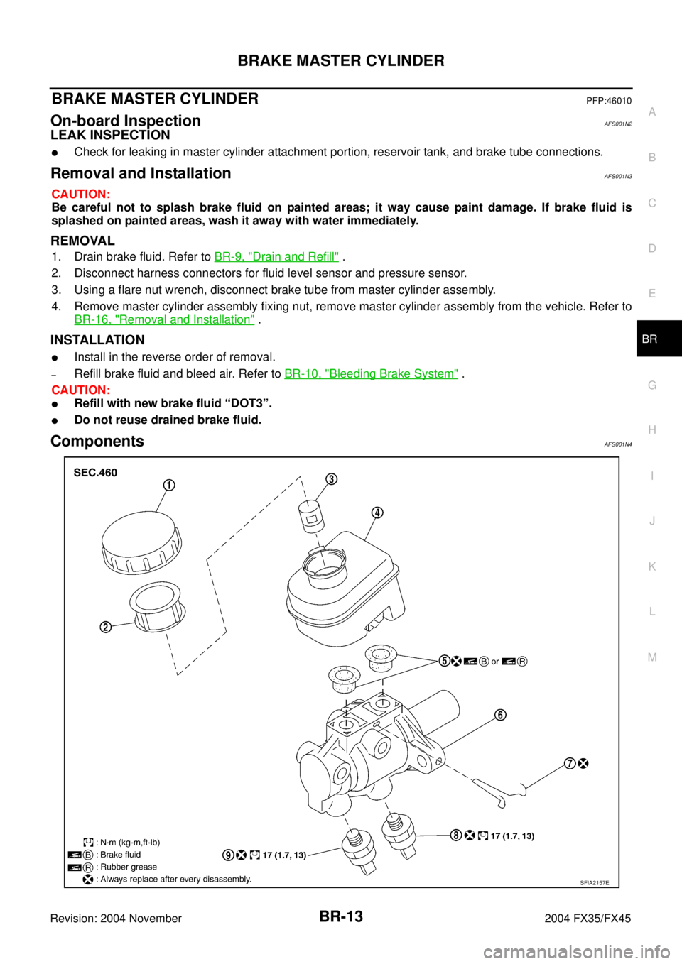
ComponentsAFS001N4
SFIA2157E