2004 INFINITI FX35 brake sensor
[x] Cancel search: brake sensorPage 158 of 4449

TROUBLE DIAGNOSIS
AT-81
D
E
F
G
H
I
J
K
L
MA
B
AT
Revision: 2004 November 2004 FX35/FX45
40
Slips/Will
Not
EngageWhile accelerating in
4th, engine races or
slippage occurs.ON vehicle1. Fluid level and stateAT- 5 1
2. Line pressure testAT- 5 2
3. Accelerator pedal position sensorAT-136
4. CAN communication lineAT-105
5. ATF pressure switch 3 and input clutch solenoid valveAT-180,
AT-152
6. Control valve with TCMAT-242
OFF vehicle7. Torque converterAT-286
8. Oil pump assemblyAT-303
9. Input clutchAT-308
10. Gear systemAT-274
11. High and low reverse clutchAT-320
12. Direct clutchAT-323
41 While accelerating in
5th, engine races or
slippage occurs.ON vehicle1. Fluid level and stateAT- 5 1
2. Line pressure testAT- 5 2
3. Accelerator pedal position sensorAT-136
4. CAN communication lineAT-105
5. ATF pressure switch 1 and front brake solenoid valveAT-178,
AT-156
6. Control valve with TCMAT-242
OFF vehicle7. Torque converterAT-286
8. Oil pump assembly AT-303
9. Front brake (brake band)AT-286
10. Input clutchAT-308
11. Gear systemAT-274
12. High and low reverse clutchAT-320
42 Slips at lock-up.ON vehicle1. Fluid level and stateAT- 5 1
2. Line pressure testAT- 5 2
3. Engine speed signalAT-121
4. Turbine revolution sensorAT-143
5. Torque converter clutch solenoid valveAT-123
6. CAN communication lineAT-105
7. Control valve with TCMAT-242
OFF vehicle8. Torque converterAT-2869. Oil pump assemblyAT-303
No. Items Symptom Condition Diagnostic ItemReference
page
Page 159 of 4449

AT-82
TROUBLE DIAGNOSIS
Revision: 2004 November 2004 FX35/FX45
43
Slips/Will
Not
EngageNo creep at all.
Refer to AT-198,
"Vehicle Does Not
Creep Backward In
“R” Position" , AT-201,
"Vehicle Does Not
Creep Forward In “D”
Position"
ON vehicle1. Fluid level and stateAT- 5 1
2. Line pressure testAT- 5 2
3. Accelerator pedal position sensorAT- 1 3 6
4. ATF pressure switch 5 and direct clutch solenoid valveAT- 1 8 2,
AT- 1 6 0
5. PNP switchAT- 11 2
6. CAN communication lineAT- 1 0 5
7. Control linkage adjustmentAT- 2 3 4
8. Control valve with TCMAT- 2 4 2
OFF vehicle9. Torque converterAT- 2 8 6
10. Oil pump assemblyAT- 3 0 3
11. 1st one-way clutchAT- 3 1 4
12. Gear systemAT- 2 7 4
13. Reverse brakeAT- 2 8 6
14. Direct clutchAT- 3 2 3
15. Forward one-way clutch (Parts behind drum support is
impossible to perform inspection by disassembly. Refer to
AT-17, "
Cross-Sectional View (2WD Models)" or AT-18,
"Cross-Sectional View (AWD Models)" )AT- 2 8 6
16. Forward brake (Parts behind drum support is impossible
to perform inspection by disassembly. Refer to AT-17,
"Cross-Sectional View (2WD Models)" or AT- 1 8 , "Cross-
Sectional View (AWD Models)" )AT- 2 8 6
44Vehicle cannot run in
all positions.ON vehicle1. Fluid level and stateAT- 5 1
2. Line pressure testAT- 5 2
3. PNP switchAT- 11 2
4. Control linkage adjustmentAT- 2 3 4
5. Control valve with TCMAT- 2 4 2
OFF vehicle6. Oil pump assemblyAT- 3 0 37. Gear systemAT- 2 7 4
8. Output shaftAT- 2 8 6
No. Items Symptom Condition Diagnostic ItemReference
page
Page 161 of 4449
AT-84
TROUBLE DIAGNOSIS
Revision: 2004 November 2004 FX35/FX45
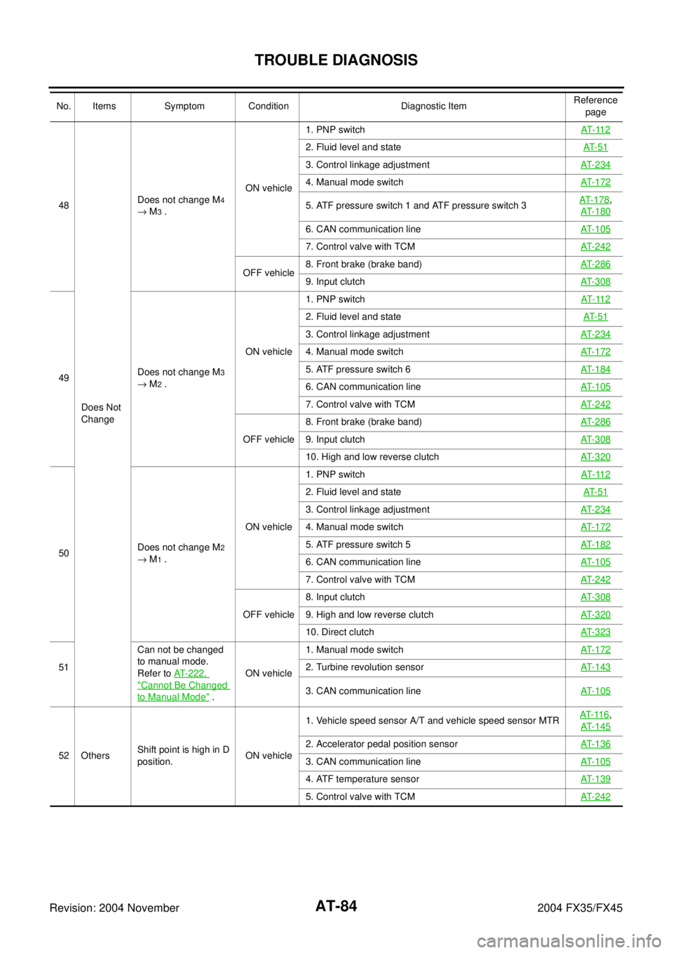
48
Does Not
ChangeDoes not change M4
→ M
3 .ON vehicle1. PNP switchAT- 11 2
2. Fluid level and stateAT- 5 1
3. Control linkage adjustmentAT- 2 3 4
4. Manual mode switchAT- 1 7 2
5. ATF pressure switch 1 and ATF pressure switch 3AT- 1 7 8,
AT- 1 8 0
6. CAN communication lineAT- 1 0 5
7. Control valve with TCMAT- 2 4 2
OFF vehicle8. Front brake (brake band)AT- 2 8 69. Input clutchAT- 3 0 8
49Does not change M3
→ M
2 .ON vehicle1. PNP switchAT- 11 2
2. Fluid level and stateAT- 5 1
3. Control linkage adjustmentAT- 2 3 4
4. Manual mode switchAT- 1 7 2
5. ATF pressure switch 6AT- 1 8 4
6. CAN communication lineAT- 1 0 5
7. Control valve with TCMAT- 2 4 2
OFF vehicle8. Front brake (brake band)AT- 2 8 69. Input clutchAT- 3 0 8
10. High and low reverse clutchAT- 3 2 0
50Does not change M2
→ M
1 .ON vehicle1. PNP switchAT- 11 2
2. Fluid level and stateAT- 5 1
3. Control linkage adjustmentAT- 2 3 4
4. Manual mode switchAT- 1 7 2
5. ATF pressure switch 5AT- 1 8 2
6. CAN communication lineAT- 1 0 5
7. Control valve with TCMAT- 2 4 2
OFF vehicle8. Input clutchAT- 3 0 89. High and low reverse clutchAT- 3 2 0
10. Direct clutchAT- 3 2 3
51Can not be changed
to manual mode.
Refer to AT-222,
"Cannot Be Changed
to Manual Mode" .ON vehicle1. Manual mode switchAT- 1 7 2
2. Turbine revolution sensorAT- 1 4 3
3. CAN communication lineAT- 1 0 5
52 OthersShift point is high in D
position.ON vehicle1. Vehicle speed sensor A/T and vehicle speed sensor MTRAT- 11 6
,
AT- 1 4 5
2. Accelerator pedal position sensorAT- 1 3 6
3. CAN communication lineAT- 1 0 5
4. ATF temperature sensorAT- 1 3 9
5. Control valve with TCMAT- 2 4 2
No. Items Symptom Condition Diagnostic ItemReference
page
Page 162 of 4449
TROUBLE DIAGNOSIS
AT-85
D
E
F
G
H
I
J
K
L
MA
B
AT
Revision: 2004 November 2004 FX35/FX45
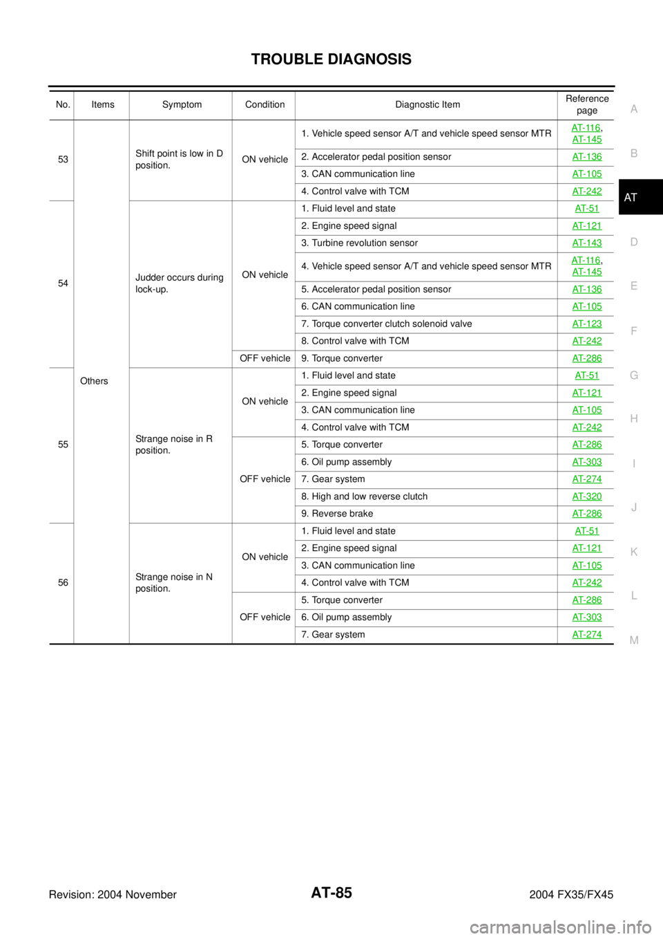
53
OthersShift point is low in D
position.ON vehicle1. Vehicle speed sensor A/T and vehicle speed sensor MTRAT- 11 6
,
AT-145
2. Accelerator pedal position sensorAT-136
3. CAN communication lineAT-105
4. Control valve with TCMAT-242
54Judder occurs during
lock-up.ON vehicle1. Fluid level and stateAT- 5 1
2. Engine speed signalAT-121
3. Turbine revolution sensorAT-143
4. Vehicle speed sensor A/T and vehicle speed sensor MTRAT- 11 6,
AT-145
5. Accelerator pedal position sensorAT-136
6. CAN communication lineAT-105
7. Torque converter clutch solenoid valveAT-123
8. Control valve with TCMAT-242
OFF vehicle 9. Torque converterAT-286
55Strange noise in R
position.ON vehicle1. Fluid level and stateAT- 5 1
2. Engine speed signalAT-121
3. CAN communication lineAT-105
4. Control valve with TCMAT-242
OFF vehicle5. Torque converterAT-286
6. Oil pump assemblyAT-303
7. Gear systemAT-274
8. High and low reverse clutchAT-320
9. Reverse brakeAT-286
56Strange noise in N
position.ON vehicle1. Fluid level and stateAT- 5 1
2. Engine speed signalAT-121
3. CAN communication lineAT-105
4. Control valve with TCMAT-242
OFF vehicle5. Torque converterAT-2866. Oil pump assemblyAT-303
7. Gear systemAT-274
No. Items Symptom Condition Diagnostic ItemReference
page
Page 164 of 4449
TROUBLE DIAGNOSIS
AT-87
D
E
F
G
H
I
J
K
L
MA
B
AT
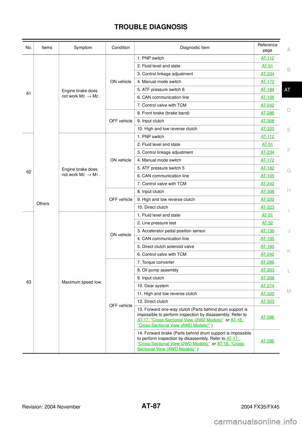
Revision: 2004 November 2004 FX35/FX4561
OthersEngine brake does
not work M3 → M2 .ON vehicle1. PNP switchAT- 11 2
2. Fluid level and stateAT- 5 1
3. Control linkage adjustmentAT-234
4. Manual mode switchAT-172
5. ATF pressure switch 6AT-184
6. CAN communication lineAT-105
7. Control valve with TCMAT-242
OFF vehicle8. Front brake (brake band)AT-2869. Input clutchAT-308
10. High and low reverse clutchAT-320
62Engine brake does
not work M2 → M1 .ON vehicle1. PNP switchAT- 11 2
2. Fluid level and stateAT- 5 1
3. Control linkage adjustmentAT-234
4. Manual mode switchAT-172
5. ATF pressure switch 5AT-182
6. CAN communication lineAT-105
7. Control valve with TCMAT-242
OFF vehicle8. Input clutchAT-3089. High and low reverse clutchAT-320
10. Direct clutchAT-323
63 Maximum speed low.ON vehicle1. Fluid level and stateAT- 5 1
2. Line pressure testAT- 5 2
3. Accelerator pedal position sensorAT-136
4. CAN communication lineAT-105
5. Direct clutch solenoid valveAT-160
6. Control valve with TCMAT-242
OFF vehicle7. Torque converter AT-286
8. Oil pump assemblyAT-303
9. Input clutchAT-308
10. Gear systemAT-274
11. High and low reverse clutchAT-320
12. Direct clutchAT-323
13. Forward one-way clutch (Parts behind drum support is
impossible to perform inspection by disassembly. Refer to
AT- 1 7 , "
Cross-Sectional View (2WD Models)" or AT- 1 8 ,
"Cross-Sectional View (AWD Models)" )AT-286
14. Forward brake (Parts behind drum support is impossible
to perform inspection by disassembly. Refer to AT-17,
"Cross-Sectional View (2WD Models)" or AT-18, "Cross-
Sectional View (AWD Models)" )AT-286
No. Items Symptom Condition Diagnostic ItemReference
page
Page 166 of 4449
TROUBLE DIAGNOSIS
AT-89
D
E
F
G
H
I
J
K
L
MA
B
AT
Revision: 2004 November 2004 FX35/FX45
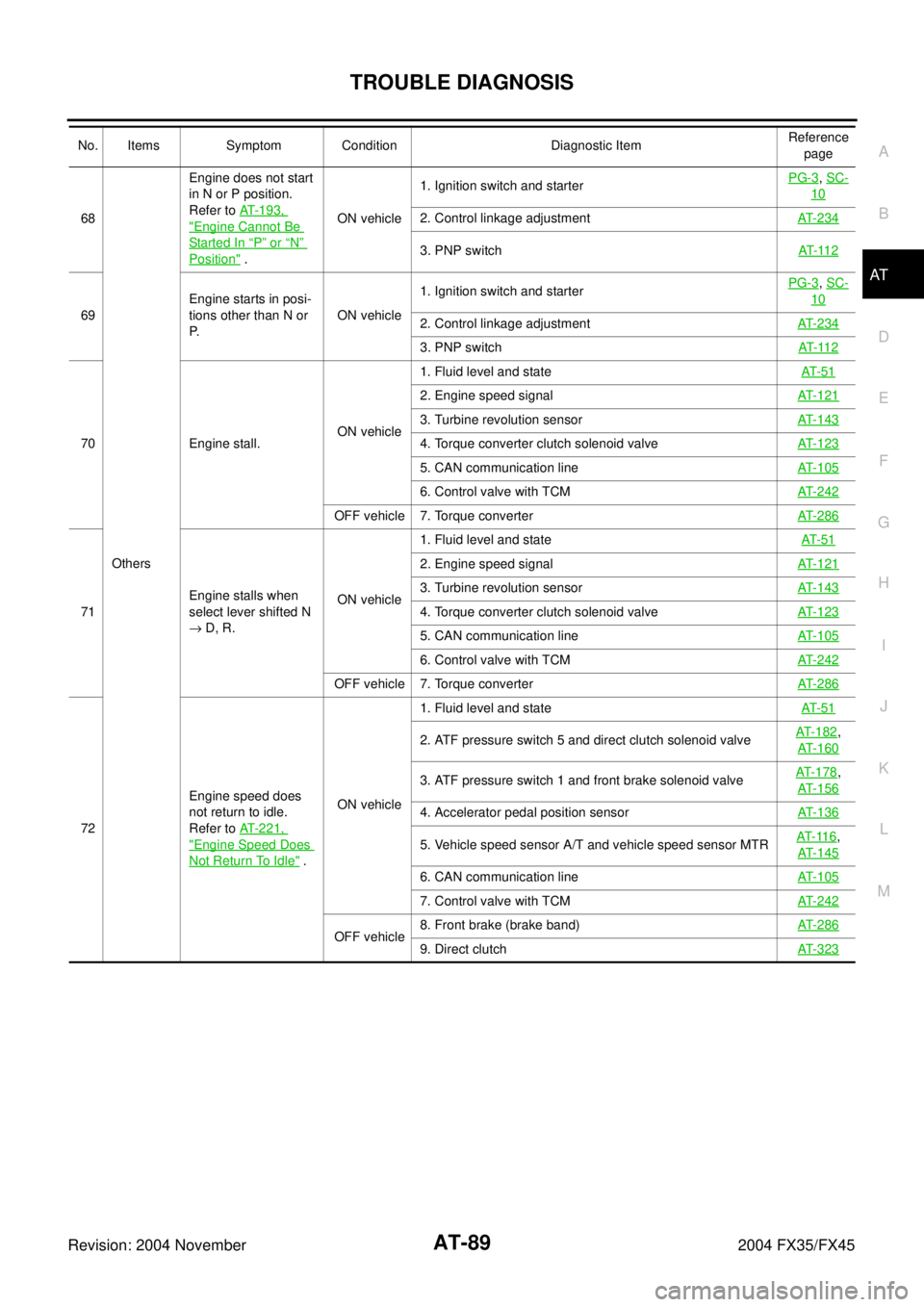
68
OthersEngine does not start
in N or P position.
Refer to AT-193, "Engine Cannot Be
Started In “P” or “N”
Position" .ON vehicle1. Ignition switch and starterPG-3
, SC-
10
2. Control linkage adjustmentAT-234
3. PNP switchAT- 11 2
69Engine starts in posi-
tions other than N or
P.ON vehicle1. Ignition switch and starterPG-3
, SC-
10
2. Control linkage adjustmentAT-234
3. PNP switchAT- 11 2
70 Engine stall.ON vehicle1. Fluid level and stateAT- 5 1
2. Engine speed signalAT-121
3. Turbine revolution sensorAT-143
4. Torque converter clutch solenoid valveAT-123
5. CAN communication lineAT-105
6. Control valve with TCMAT-242
OFF vehicle 7. Torque converterAT-286
71Engine stalls when
select lever shifted N
→ D, R.ON vehicle1. Fluid level and stateAT- 5 1
2. Engine speed signalAT-121
3. Turbine revolution sensorAT-143
4. Torque converter clutch solenoid valveAT-123
5. CAN communication lineAT-105
6. Control valve with TCMAT-242
OFF vehicle 7. Torque converterAT-286
72Engine speed does
not return to idle.
Refer to AT-221,
"Engine Speed Does
Not Return To Idle" .ON vehicle1. Fluid level and stateAT- 5 1
2. ATF pressure switch 5 and direct clutch solenoid valveAT-182,
AT-160
3. ATF pressure switch 1 and front brake solenoid valveAT-178
,
AT-156
4. Accelerator pedal position sensorAT-136
5. Vehicle speed sensor A/T and vehicle speed sensor MTRAT- 11 6,
AT-145
6. CAN communication lineAT-105
7. Control valve with TCMAT-242
OFF vehicle8. Front brake (brake band)AT-2869. Direct clutchAT-323
No. Items Symptom Condition Diagnostic ItemReference
page
Page 168 of 4449
TROUBLE DIAGNOSIS
AT-91
D
E
F
G
H
I
J
K
L
MA
B
AT
Revision: 2004 November 2004 FX35/FX45
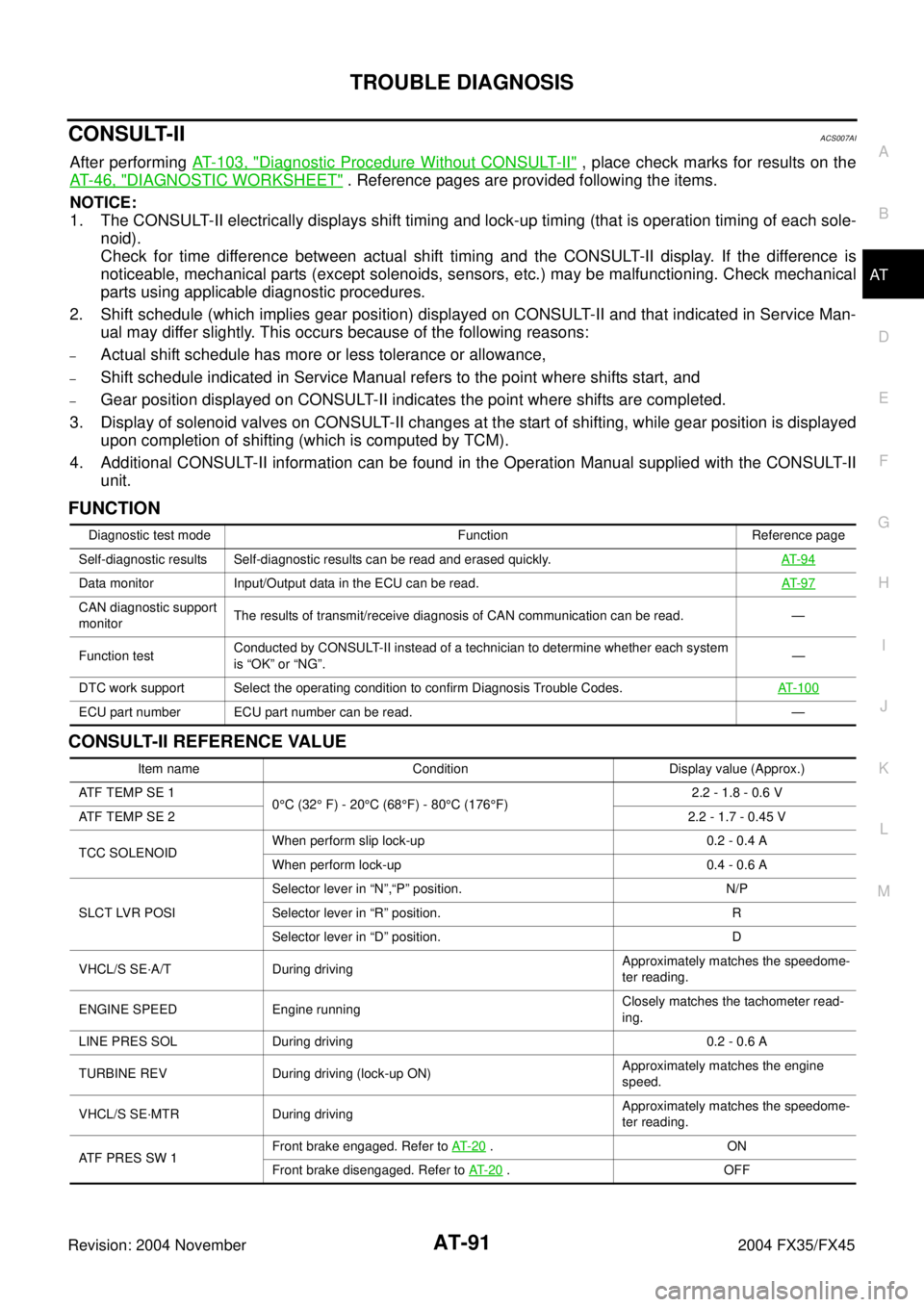
CONSULT-IIACS007AI
After performing AT- 1 0 3 , "Diagnostic Procedure Without CONSULT-II" , place check marks for results on the
AT- 4 6 , "
DIAGNOSTIC WORKSHEET" . Reference pages are provided following the items.
NOTICE:
1. The CONSULT-II electrically displays shift timing and lock-up timing (that is operation timing of each sole-
noid).
Check for time difference between actual shift timing and the CONSULT-II display. If the difference is
noticeable, mechanical parts (except solenoids, sensors, etc.) may be malfunctioning. Check mechanical
parts using applicable diagnostic procedures.
2. Shift schedule (which implies gear position) displayed on CONSULT-II and that indicated in Service Man-
ual may differ slightly. This occurs because of the following reasons:
–Actual shift schedule has more or less tolerance or allowance,
–Shift schedule indicated in Service Manual refers to the point where shifts start, and
–Gear position displayed on CONSULT-II indicates the point where shifts are completed.
3. Display of solenoid valves on CONSULT-II changes at the start of shifting, while gear position is displayed
upon completion of shifting (which is computed by TCM).
4. Additional CONSULT-II information can be found in the Operation Manual supplied with the CONSULT-II
unit.
FUNCTION
CONSULT-II REFERENCE VALUE
Diagnostic test mode Function Reference page
Self-diagnostic results Self-diagnostic results can be read and erased quickly.AT- 9 4
Data monitor Input/Output data in the ECU can be read.AT- 9 7
CAN diagnostic support
monitorThe results of transmit/receive diagnosis of CAN communication can be read. —
Function testConducted by CONSULT-II instead of a technician to determine whether each system
is “OK” or “NG”.—
DTC work support Select the operating condition to confirm Diagnosis Trouble Codes.AT-100
ECU part number ECU part number can be read. —
Item name Condition Display value (Approx.)
ATF TEMP SE 1
0°C (32° F) - 20°C (68°F) - 80°C (176°F)2.2 - 1.8 - 0.6 V
ATF TEMP SE 22.2 - 1.7 - 0.45 V
TCC SOLENOIDWhen perform slip lock-up 0.2 - 0.4 A
When perform lock-up 0.4 - 0.6 A
SLCT LVR POSISelector lever in “N”,“P” position. N/P
Selector lever in “R” position. R
Selector lever in “D” position. D
VHCL/S SE·A/T During drivingApproximately matches the speedome-
ter reading.
ENGINE SPEED Engine runningClosely matches the tachometer read-
ing.
LINE PRES SOL During driving 0.2 - 0.6 A
TURBINE REV During driving (lock-up ON)Approximately matches the engine
speed.
VHCL/S SE·MTR During drivingApproximately matches the speedome-
ter reading.
ATF PRES SW 1Front brake engaged. Refer to AT- 2 0
.ON
Front brake disengaged. Refer to AT- 2 0
.OFF
Page 174 of 4449

TROUBLE DIAGNOSIS
AT-97
D
E
F
G
H
I
J
K
L
MA
B
AT
Revision: 2004 November 2004 FX35/FX45
How to Erase Self-diagnostic Results
1. Perform “CONSULT-II SETTING PROCEDURE” Refer to AT- 9 3 ,
"CONSULT-II SETTING PROCEDURE" .
2. Touch “SELF-DIAG RESULTS”.
3. Touch ”ERASE”. (The self-diagnostic results will be erased.)
DATA MONITOR MODE
Operation Procedure
1. Perform “CONSULT-II SETTING PROCEDURE” Refer to AT- 9 3 ,
"CONSULT-II SETTING PROCEDURE" .
2. Touch “DATA MONITOR”.
NOTE:
When malfunction is detected, CONSULT-II performs
“REAL-TIME DIAGNOSIS”. Also, any malfunction detected
while in this mode will be displayed at real time.
Display Items List
X: Standard, —: Not applicable
SCIA5304E
PCIA0061E
SCIA5304E
Monitored item (Unit)Monitor Item Selection
Remarks ECU
INPUT
SIGNALSMAIN SIG-
NALSSELEC-
TION
FROM
MENU
VHCL/S SE·A/T (km/h) X X X Revolution sensor
VHCL/S SE·MTR (km/h) X — X
ACCELE POSI (0.0/8) X — X Accelerator pedal position signal
THROTTLE POSI (0.0/8) X X XDegree of opening for accelerator recognized by
the TCM
For fail-safe operation, the specific value used
for control is displayed.
CLSD THL POS (ON-OFF display) X — X
Signal input with CAN communications
W/O THL POS (ON-OFF display) X — X
BRAKE SW (ON-OFF display) X — X Stop lamp switch