2004 INFINITI FX35 rear door
[x] Cancel search: rear doorPage 1006 of 4449
VEHICLE SECURITY (THEFT WARNING) SYSTEM
BL-199
C
D
E
F
G
H
J
K
L
MA
B
BL
Revision: 2004 November 2004 FX35/FX45
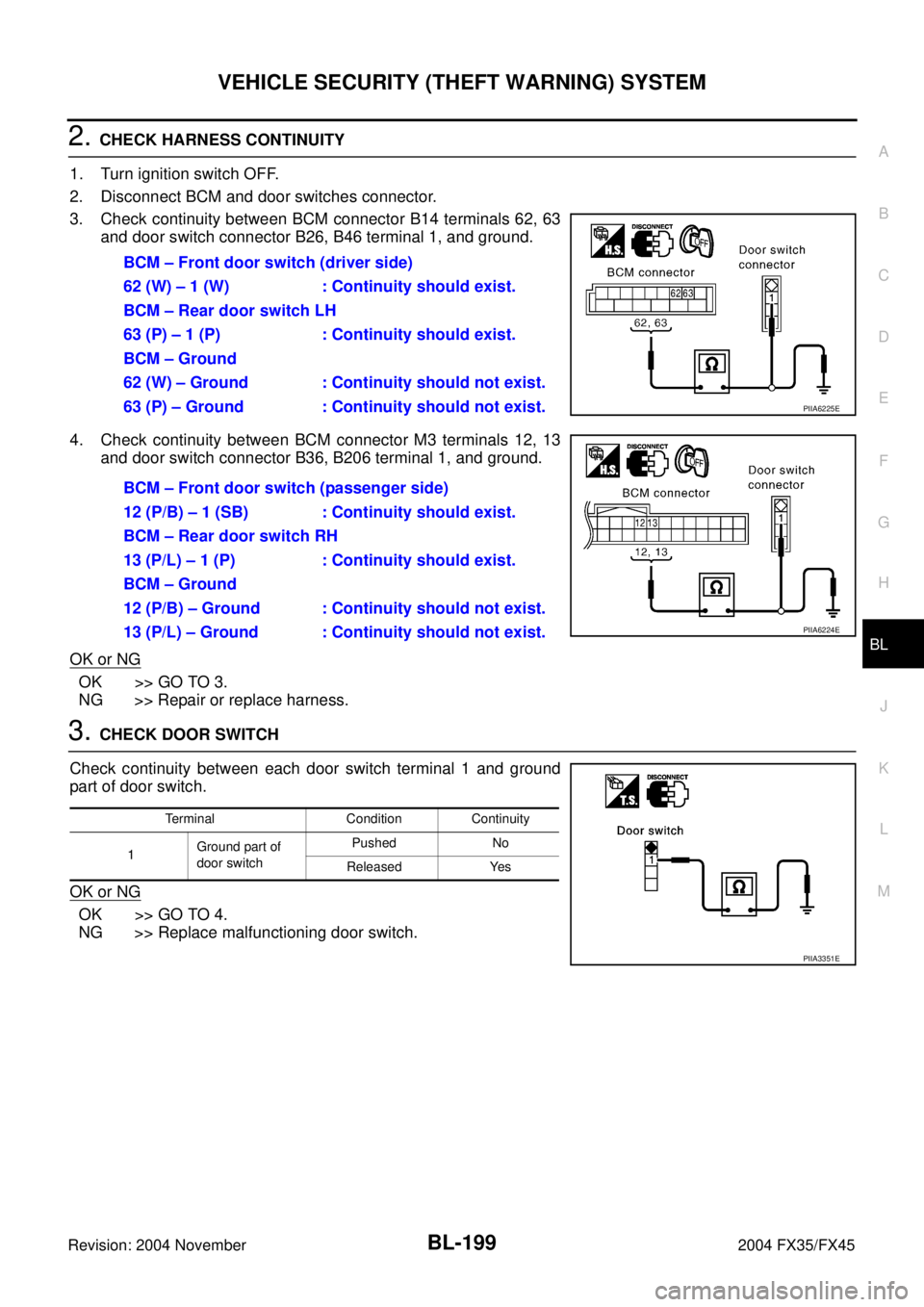
2. CHECK HARNESS CONTINUITY
1. Turn ignition switch OFF.
2. Disconnect BCM and door switches connector.
3. Check continuity between BCM connector B14 terminals 62, 63
and door switch connector B26, B46 terminal 1, and ground.
4. Check continuity between BCM connector M3 terminals 12, 13
and door switch connector B36, B206 terminal 1, and ground.
OK or NG
OK >> GO TO 3.
NG >> Repair or replace harness.
3. CHECK DOOR SWITCH
Check continuity between each door switch terminal 1 and ground
part of door switch.
OK or NG
OK >> GO TO 4.
NG >> Replace malfunctioning door switch.BCM – Front door switch (driver side)
62 (W) – 1 (W) : Continuity should exist.
BCM – Rear door switch LH
63 (P) – 1 (P) : Continuity should exist.
BCM – Ground
62 (W) – Ground : Continuity should not exist.
63 (P) – Ground : Continuity should not exist.
PIIA6225E
BCM – Front door switch (passenger side)
12 (P/B) – 1 (SB) : Continuity should exist.
BCM – Rear door switch RH
13 (P/L) – 1 (P) : Continuity should exist.
BCM – Ground
12 (P/B) – Ground : Continuity should not exist.
13 (P/L) – Ground : Continuity should not exist.
PIIA6224E
Terminal Condition Continuity
1Ground part of
door switchPushed No
Released Yes
PIIA3351E
Page 1038 of 4449
BODY REPAIR
BL-231
C
D
E
F
G
H
J
K
L
MA
B
BL
Revision: 2004 November2004 FX35/FX45
BODY REPAIRPFP:60100
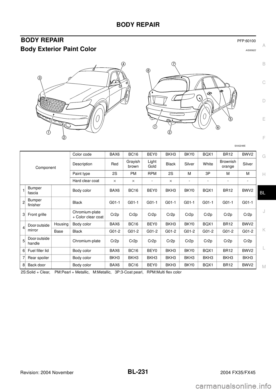
Body Exterior Paint ColorAIS00622
2S:Solid + Clear, PM:Pearl + Metallic, M:Metallic, 3P:3-Coat pearl, RPM:Multi flex color
SIIA2248E
ComponentColor code BAX6 BC16 BEY0 BKH3 BKY0 BQX1 BR12 BWV2
Description RedGrayish
brownLight
GoldBlack Silver WhiteBrownish
orangeSilver
Paint type 2S PM RPM 2S M 3P M M
Hard clear coat´´-´-- - -
1Bumper
fasciaBody color BAX6 BC16 BEY0 BKH3 BKY0 BQX1 BR12 BWV2
2Bumper
finisherBlack G01-1 G01-1 G01-1 G01-1 G01-1 G01-1 G01-1 G01-1
3 Front grilleChromium-plate
+ Color clear coatCr2p Cr2p Cr2p Cr2p Cr2p Cr2p Cr2p Cr2p
4Door outside
mirrorHousing Body color BAX6 BC16 BEY0 BKH3 BKY0 BQX1 BR12 BWV2
Base Black G01-2 G01-2 G01-2 G01-2 G01-2 G01-2 G01-2 G01-2
5Door outside
handleChromium-plate Cr2p Cr2p Cr2p Cr2p Cr2p Cr2p Cr2p Cr2p
6 Fuel filler lid Body color BAX6 BC16 BEY0 BKH3 BKY0 BQX1 BR12 BWV2
7 Rear spoiler Body color BKH3 BKH3 BKH3 BKH3 BKH3 BKH3 BKH3 BKH3
8 Back door Body color BAX6 BC16 BEY0 BKH3 BKY0 BQX1 BR12 BWV2
Page 1042 of 4449
BODY REPAIR
BL-235
C
D
E
F
G
H
J
K
L
MA
B
BL
Revision: 2004 November2004 FX35/FX45
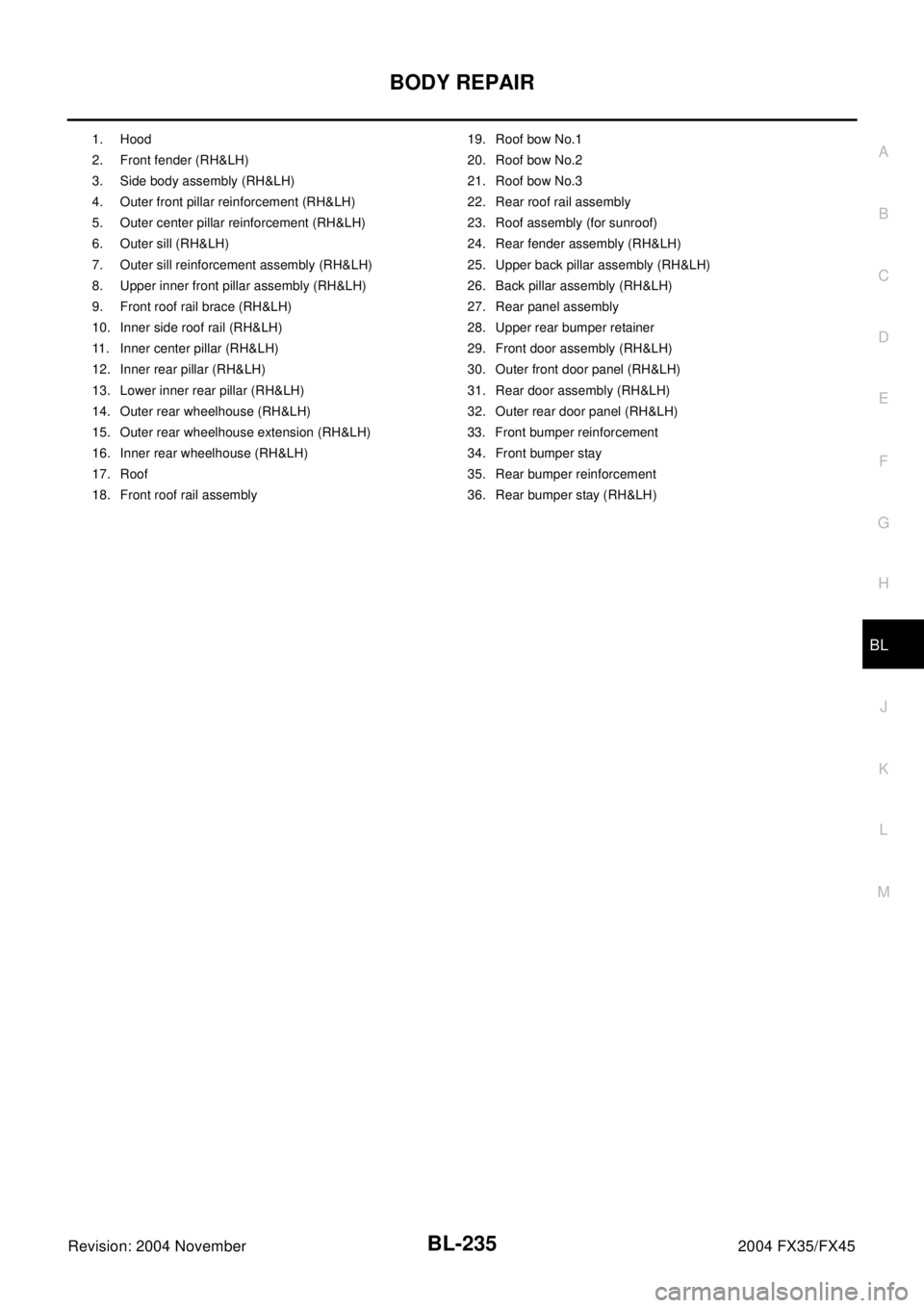
1. Hood 19. Roof bow No.1
2. Front fender (RH&LH) 20. Roof bow No.2
3. Side body assembly (RH&LH) 21. Roof bow No.3
4. Outer front pillar reinforcement (RH&LH) 22. Rear roof rail assembly
5. Outer center pillar reinforcement (RH&LH) 23. Roof assembly (for sunroof)
6. Outer sill (RH&LH) 24. Rear fender assembly (RH&LH)
7. Outer sill reinforcement assembly (RH&LH) 25. Upper back pillar assembly (RH&LH)
8. Upper inner front pillar assembly (RH&LH) 26. Back pillar assembly (RH&LH)
9. Front roof rail brace (RH&LH) 27. Rear panel assembly
10. Inner side roof rail (RH&LH) 28. Upper rear bumper retainer
11. Inner center pillar (RH&LH) 29. Front door assembly (RH&LH)
12. Inner rear pillar (RH&LH) 30. Outer front door panel (RH&LH)
13. Lower inner rear pillar (RH&LH) 31. Rear door assembly (RH&LH)
14. Outer rear wheelhouse (RH&LH) 32. Outer rear door panel (RH&LH)
15. Outer rear wheelhouse extension (RH&LH) 33. Front bumper reinforcement
16. Inner rear wheelhouse (RH&LH) 34. Front bumper stay
17. Roof 35. Rear bumper reinforcement
18. Front roof rail assembly 36. Rear bumper stay (RH&LH)
Page 1340 of 4449

REAR VIEW MONITOR
DI-97
C
D
E
F
G
H
I
J
L
MA
B
DI
Revision: 2004 November 2004 FX35/FX45
3. CHECK REAR VIEW CONTROL UNIT SYNCHRO SIGNAL
1. Connect rear view camera control unit connector and display connector.
2. Turn ignition switch ON.
3. Check voltage signal between rear view camera control unit har-
ness connector M48 terminal 14 (Y) and ground.
OK or NG
OK >> Replace rear view camera control unit.
NG >> Replace display.
Removal and Installation of Rear View Camera Control UnitAKS0068Q
REMOVAL
1. Remove instrument clock finisher and A/T console finisher.
Refer to IP-11, "
WORK STEP" .
2. Remove screws (2), and remove rear view camera control unit.
INSTALLATION
Install in the reverse order of removal.
Removal and Installation of Rear View CameraAKS0068R
REMOVAL
1. Remove back door finisher lower. Refer to EI-46, "Removal and
Installation" .
2. Cut off back door module along the line.
3. Remove connector.14 (Y) - Ground:
SKIA5103E
SKIA5896E
SKIA5797E
SKIA6168E
Page 2680 of 4449
EI-1
EXTERIOR & INTERIOR
I BODY
CONTENTS
C
D
E
F
G
H
J
K
L
M
SECTION EI
A
B
EI
Revision: 2004 November 2004 FX35/FX45
EXTERIOR & INTERIOR
PRECAUTIONS .......................................................... 3
Precautions for Supplemental Restraint System
(SRS) “AIR BAG” and “SEAT BELT PRE-TEN-
SIONER” .................................................................. 3
Precautions for Work ................................................ 3
PREPARATION ........................................................... 4
Special Service Tools ............................................... 4
Commercial Service Tools ........................................ 4
SQUEAK AND RATTLE TROUBLE DIAGNOSES ..... 5
Work Flow ................................................................ 5
CUSTOMER INTERVIEW ..................................... 5
DUPLICATE THE NOISE AND TEST DRIVE ....... 6
CHECK RELATED SERVICE BULLETINS ........... 6
LOCATE THE NOISE AND IDENTIFY THE
ROOT CAUSE ...................................................... 6
REPAIR THE CAUSE ........................................... 6
CONFIRM THE REPAIR ....................................... 7
Generic Squeak and Rattle Troubleshooting ........... 7
INSTRUMENT PANEL .......................................... 7
CENTER CONSOLE ............................................. 7
DOORS ................................................................. 7
TRUNK .................................................................. 8
SUNROOF/HEADLINING ..................................... 8
SEATS ................................................................... 8
UNDERHOOD ....................................................... 8
Diagnostic Worksheet .............................................. 9
CLIP AND FASTENER ..............................................11
Clip and Fastener .................................................... 11
FRONT BUMPER ..................................................... 14
Removal and Installation ........................................ 14
REMOVAL ........................................................... 16
INSTALLATION ................................................... 16
FRONT FILLET MOLDING ASSEMBLY ............. 17REAR BUMPER ........................................................ 18
Removal and Installation ........................................ 18
REMOVAL ........................................................... 20
INSTALLATION ................................................... 21
REAR BUMPER FASCIA .................................... 21
REAR BUMPER CLOSING ................................. 22
DRAFTER GUARD ............................................. 22
REAR FILLET MOLDING ASSEMBLY ................ 22
FRONT GRILLE ........................................................ 23
Removal and Installation ........................................ 23
REMOVAL ........................................................... 23
INSTALLATION ................................................... 23
COWL TOP ............................................................... 24
Removal and Installation ........................................ 24
REMOVAL ........................................................... 24
INSTALLATION ................................................... 24
FENDER PROTECTOR ............................................ 25
Removal and Installation ........................................ 25
REMOVAL ........................................................... 25
INSTALLATION ................................................... 25
DOOR OUTSIDE MOLDING ..................................... 26
Removal and Installation ........................................ 26
FRONT DOOR OUTSIDE MOLDING .................. 26
REAR DOOR OUTSIDE MOLDING .................... 26
DOOR OUTSIDE LOWER MOLDING ...................... 27
Removal and Installation ........................................ 27
FRONT AND REAR DOOR OUTSIDE LOWER
MOLDING ............................................................ 27
DOOR PARTING SEAL ............................................ 28
Removal and Installation ........................................ 28
REMOVAL ........................................................... 28
INSTALLATION ................................................... 28
CENTER MUD GUARD ............................................ 29
Removal and Installation ........................................ 29
REMOVAL ........................................................... 29
INSTALLATION ................................................... 29
WINDSHIELD MOLDING .......................................... 30
Removal and Installation ........................................ 30
REMOVAL ........................................................... 30
INSTALLATION ................................................... 30
Page 2681 of 4449
EI-2Revision: 2004 November 2004 FX35/FX45 BACK DOOR WINDOW MOLDING .......................... 31
Removal and Installation ........................................ 31
REMOVAL ........................................................... 31
INSTALLATION .................................................... 31
ROOF SIDE MOLDING ............................................. 33
Removal and Installation ........................................ 33
REMOVAL ........................................................... 33
INSTALLATION .................................................... 33
ROOF RAIL ............................................................... 34
Removal and Installation ........................................ 34
REMOVAL ........................................................... 34
INSTALLATION .................................................... 34
ROOF RAIL BRACKET ....................................... 34
DOOR FINISHER ...................................................... 35
Removal and Installation ........................................ 35
DOOR FINISHER (FRONT AND REAR) ............. 35
BODY SIDE TRIM ..................................................... 37
Removal and Installation ........................................ 37
CENTER PILLAR LOWER GARNISH ................. 37
CENTER PILLAR UPPER GARNISH .................. 38
DASH SIDE FINISHER ....................................... 38
FRONT PILLAR GARNISH ................................. 39
KICKING PLATE .................................................. 39
CENTER MUDGUARD FINISHER (FRONT/REAR) .................................................................. 39
FLOOR TRIM ............................................................. 40
Removal and Installation ......................................... 40
REMOVAL ............................................................ 40
INSTALLATION .................................................... 41
HEADLINING ............................................................. 42
Removal and Installation ......................................... 42
REMOVAL ............................................................ 43
INSTALLATION .................................................... 43
LUGGAGE FLOOR TRIM ......................................... 44
Removal and Installation ......................................... 44
REMOVAL ............................................................ 45
INSTALLATION .................................................... 45
BACK DOOR TRIM ................................................... 46
Removal and Installation ......................................... 46
REMOVAL ............................................................ 46
INSTALLATION .................................................... 46
BACK DOOR OUTSIDE FINISHER ..................... 46
Page 2705 of 4449
EI-26
DOOR OUTSIDE MOLDING
Revision: 2004 November 2004 FX35/FX45
DOOR OUTSIDE MOLDING PFP:82820
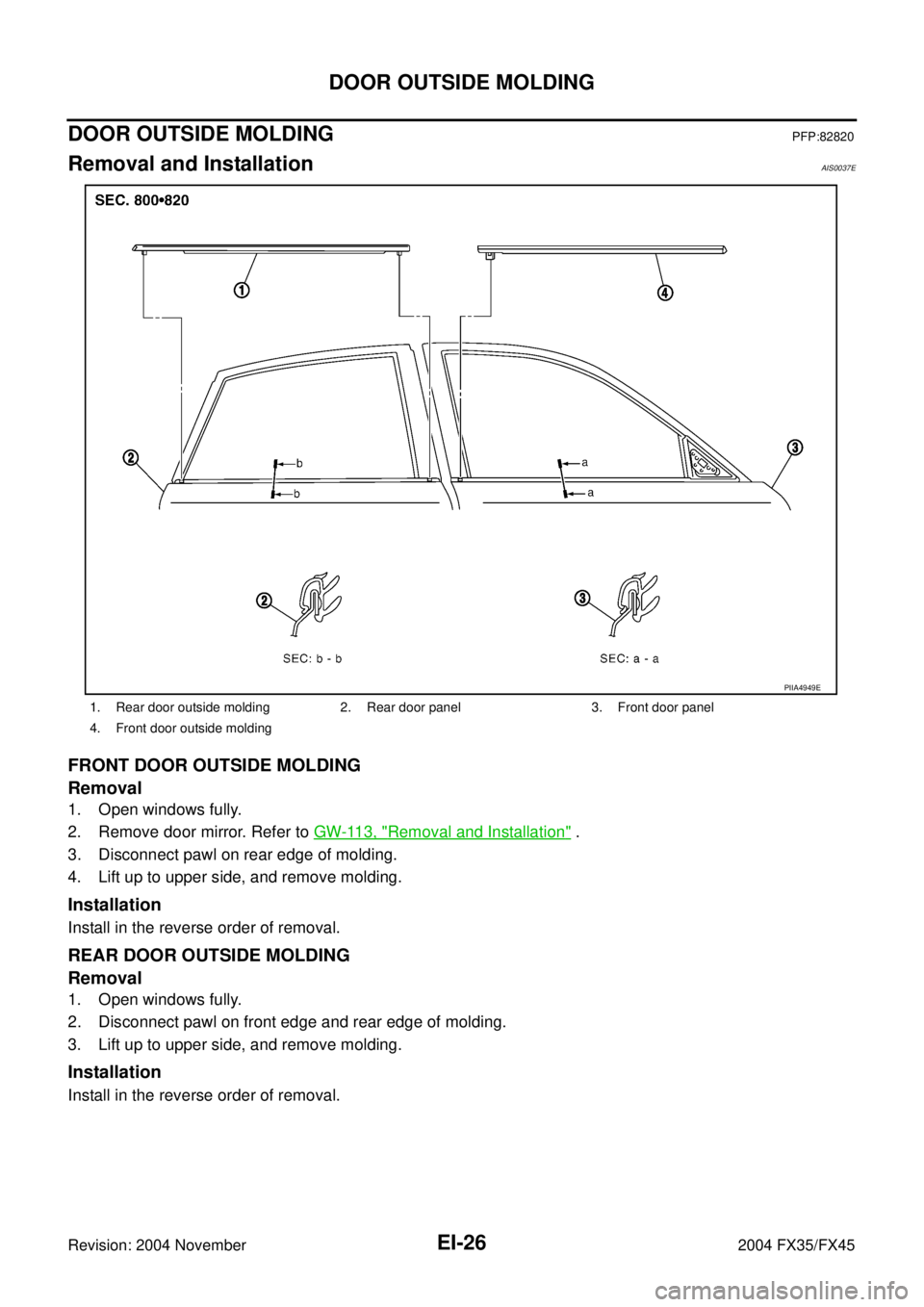
Removal and InstallationAIS0037E
FRONT DOOR OUTSIDE MOLDING
Removal
1. Open windows fully.
2. Remove door mirror. Refer to GW-113, "
Removal and Installation" .
3. Disconnect pawl on rear edge of molding.
4. Lift up to upper side, and remove molding.
Installation
Install in the reverse order of removal.
REAR DOOR OUTSIDE MOLDING
Removal
1. Open windows fully.
2. Disconnect pawl on front edge and rear edge of molding.
3. Lift up to upper side, and remove molding.
Installation
Install in the reverse order of removal.
1. Rear door outside molding 2. Rear door panel 3. Front door panel
4. Front door outside molding
PIIA4949E
Page 2706 of 4449
DOOR OUTSIDE LOWER MOLDING
EI-27
C
D
E
F
G
H
J
K
L
MA
B
EI
Revision: 2004 November 2004 FX35/FX45
DOOR OUTSIDE LOWER MOLDINGPFP:82877
Removal and InstallationAIS0037F
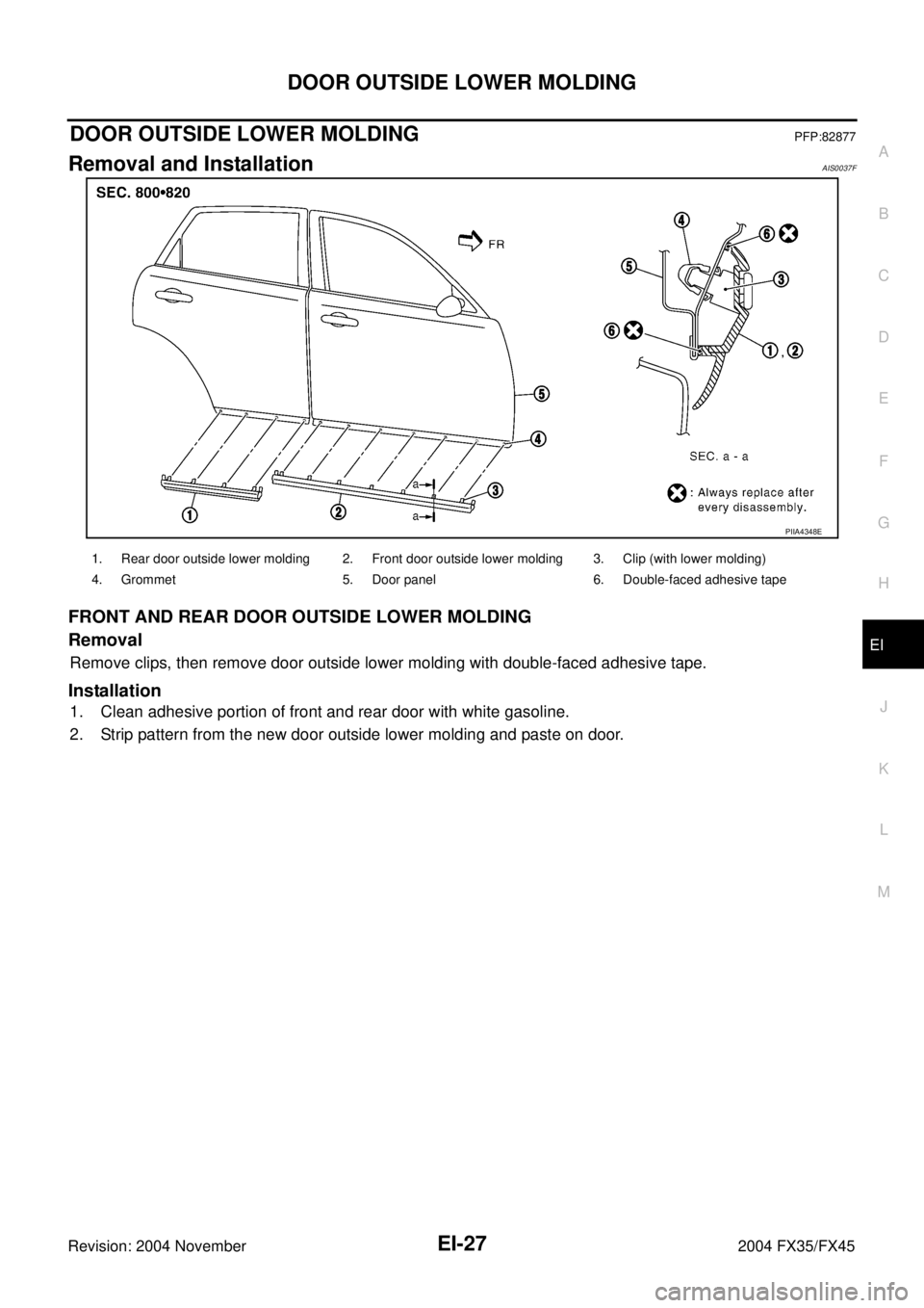
FRONT AND REAR DOOR OUTSIDE LOWER MOLDING
Removal
Remove clips, then remove door outside lower molding with double-faced adhesive tape.
Installation
1. Clean adhesive portion of front and rear door with white gasoline.
2. Strip pattern from the new door outside lower molding and paste on door.
PIIA4348E
1. Rear door outside lower molding 2. Front door outside lower molding 3. Clip (with lower molding)
4. Grommet 5. Door panel 6. Double-faced adhesive tape