Page 3579 of 4449
LT-24
HEADLAMP - XENON TYPE -
Revision: 2004 November 2004 FX35/FX45
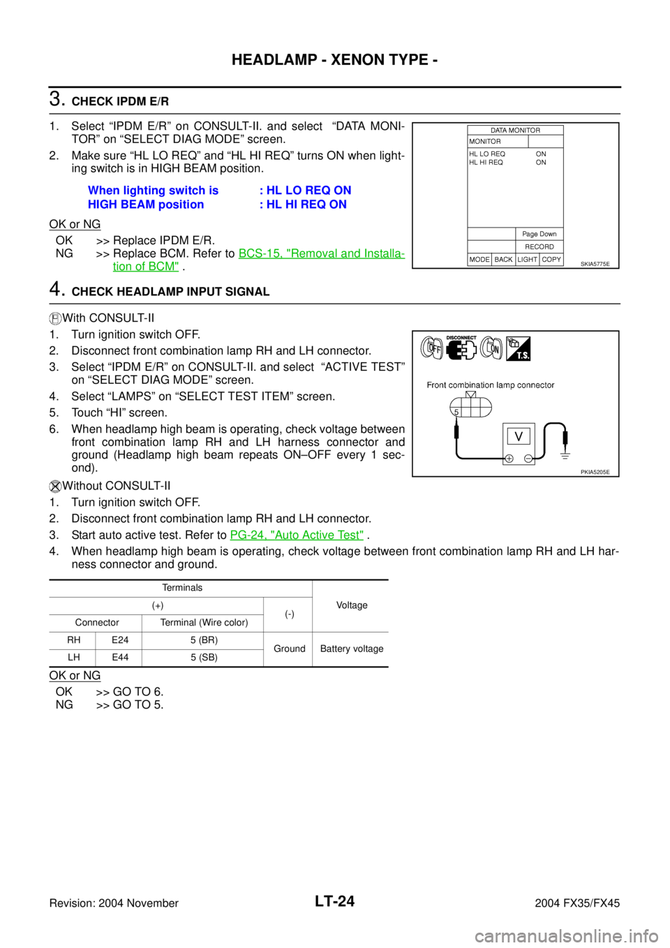
3. CHECK IPDM E/R
1. Select “IPDM E/R” on CONSULT-II. and select “DATA MONI-
TOR” on “SELECT DIAG MODE” screen.
2. Make sure “HL LO REQ” and “HL HI REQ” turns ON when light-
ing switch is in HIGH BEAM position.
OK or NG
OK >> Replace IPDM E/R.
NG >> Replace BCM. Refer to BCS-15, "
Removal and Installa-
tion of BCM" .
4. CHECK HEADLAMP INPUT SIGNAL
With CONSULT-II
1. Turn ignition switch OFF.
2. Disconnect front combination lamp RH and LH connector.
3. Select “IPDM E/R” on CONSULT-II. and select “ACTIVE TEST”
on “SELECT DIAG MODE” screen.
4. Select “LAMPS” on “SELECT TEST ITEM” screen.
5. Touch “HI” screen.
6. When headlamp high beam is operating, check voltage between
front combination lamp RH and LH harness connector and
ground (Headlamp high beam repeats ON–OFF every 1 sec-
ond).
Without CONSULT-II
1. Turn ignition switch OFF.
2. Disconnect front combination lamp RH and LH connector.
3. Start auto active test. Refer to PG-24, "
Auto Active Test" .
4. When headlamp high beam is operating, check voltage between front combination lamp RH and LH har-
ness connector and ground.
OK or NG
OK >> GO TO 6.
NG >> GO TO 5.When lighting switch is
HIGH BEAM position: HL LO REQ ON
: HL HI REQ ON
SKIA5775E
Terminals
Voltage (+)
(-)
Connector Terminal (Wire color)
RH E24 5 (BR)
Ground Battery voltage
LH E44 5 (SB)
PKIA5205E
Page 3580 of 4449
HEADLAMP - XENON TYPE -
LT-25
C
D
E
F
G
H
I
J
L
MA
B
LT
Revision: 2004 November 2004 FX35/FX45
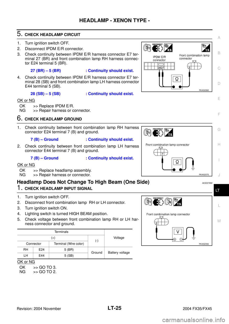
5. CHECK HEADLAMP CIRCUIT
1. Turn ignition switch OFF.
2. Disconnect IPDM E/R connector.
3. Check continuity between IPDM E/R harness connector E7 ter-
minal 27 (BR) and front combination lamp RH harness connec-
tor E24 terminal 5 (BR).
4. Check continuity between IPDM E/R harness connector E7 ter-
minal 28 (SB) and front combination lamp LH harness connector
E44 terminal 5 (SB).
OK or NG
OK >> Replace IPDM E/R.
NG >> Repair harness or connector.
6. CHECK HEADLAMP GROUND
1. Check continuity between front combination lamp RH harness
connector E24 terminal 7 (B) and ground.
2. Check continuity between front combination lamp LH harness
connector E44 terminal 7 (B) and ground.
OK or NG
OK >> Replace headlamp assembly.
NG >> Repair harness or connector.
Headlamp Does Not Change To High Beam (One Side)AKS007MM
1. CHECK HEADLAMP INPUT SIGNAL
1. Turn ignition switch OFF.
2. Disconnect front combination lamp RH or LH connector.
3. Turn ignition switch ON.
4. Lighting switch is turned HIGH BEAM position.
5. Check voltage between front combination lamp RH or LH har-
ness connector and ground.
OK or NG
OK >> GO TO 3.
NG >> GO TO 2.27 (BR) – 5 (BR) : Continuity should exist.
28 (SB) – 5 (SB) : Continuity should exist.
PKIA5206E
7 (B) – Ground : Continuity should exist.
7 (B) – Ground : Continuity should exist.
PKIA5207E
Terminals
Voltage (+)
(-)
Connector Terminal (Wire color)
RH E24 5 (BR)
Ground Battery voltage
LH E44 5 (SB)
PKIA5205E
Page 3583 of 4449
LT-28
HEADLAMP - XENON TYPE -
Revision: 2004 November 2004 FX35/FX45
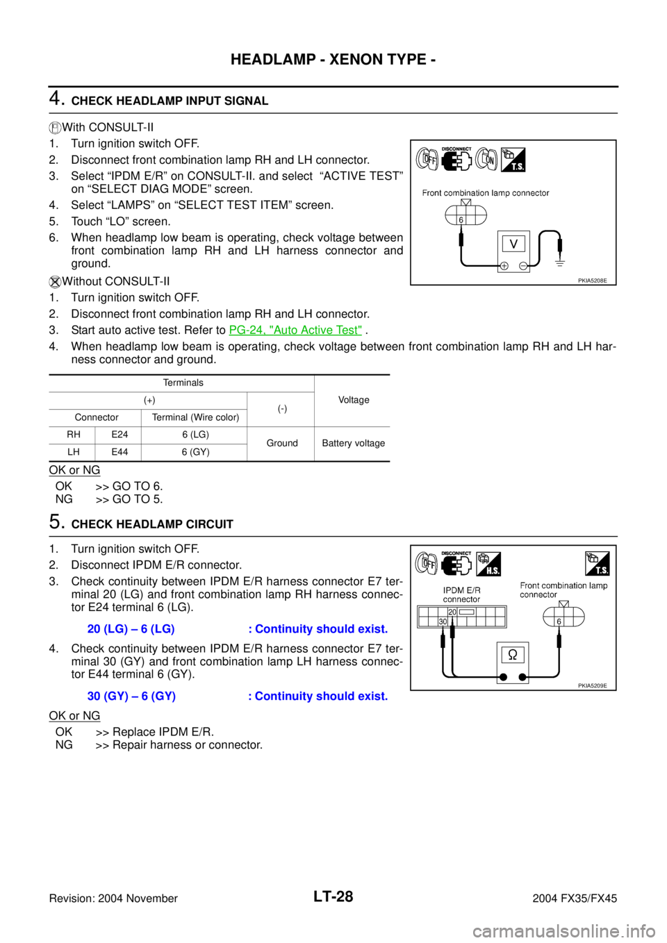
4. CHECK HEADLAMP INPUT SIGNAL
With CONSULT-II
1. Turn ignition switch OFF.
2. Disconnect front combination lamp RH and LH connector.
3. Select “IPDM E/R” on CONSULT-II. and select “ACTIVE TEST”
on “SELECT DIAG MODE” screen.
4. Select “LAMPS” on “SELECT TEST ITEM” screen.
5. Touch “LO” screen.
6. When headlamp low beam is operating, check voltage between
front combination lamp RH and LH harness connector and
ground.
Without CONSULT-II
1. Turn ignition switch OFF.
2. Disconnect front combination lamp RH and LH connector.
3. Start auto active test. Refer to PG-24, "
Auto Active Test" .
4. When headlamp low beam is operating, check voltage between front combination lamp RH and LH har-
ness connector and ground.
OK or NG
OK >> GO TO 6.
NG >> GO TO 5.
5. CHECK HEADLAMP CIRCUIT
1. Turn ignition switch OFF.
2. Disconnect IPDM E/R connector.
3. Check continuity between IPDM E/R harness connector E7 ter-
minal 20 (LG) and front combination lamp RH harness connec-
tor E24 terminal 6 (LG).
4. Check continuity between IPDM E/R harness connector E7 ter-
minal 30 (GY) and front combination lamp LH harness connec-
tor E44 terminal 6 (GY).
OK or NG
OK >> Replace IPDM E/R.
NG >> Repair harness or connector.
Te r m i n a l s
Vo l ta g e (+)
(-)
Connector Terminal (Wire color)
RH E24 6 (LG)
Ground Battery voltage
LH E44 6 (GY)
PKIA5208E
20 (LG) – 6 (LG) : Continuity should exist.
30 (GY) – 6 (GY) : Continuity should exist.
PKIA5209E
Page 3590 of 4449
HEADLAMP - XENON TYPE -
LT-35
C
D
E
F
G
H
I
J
L
MA
B
LT
Revision: 2004 November 2004 FX35/FX45
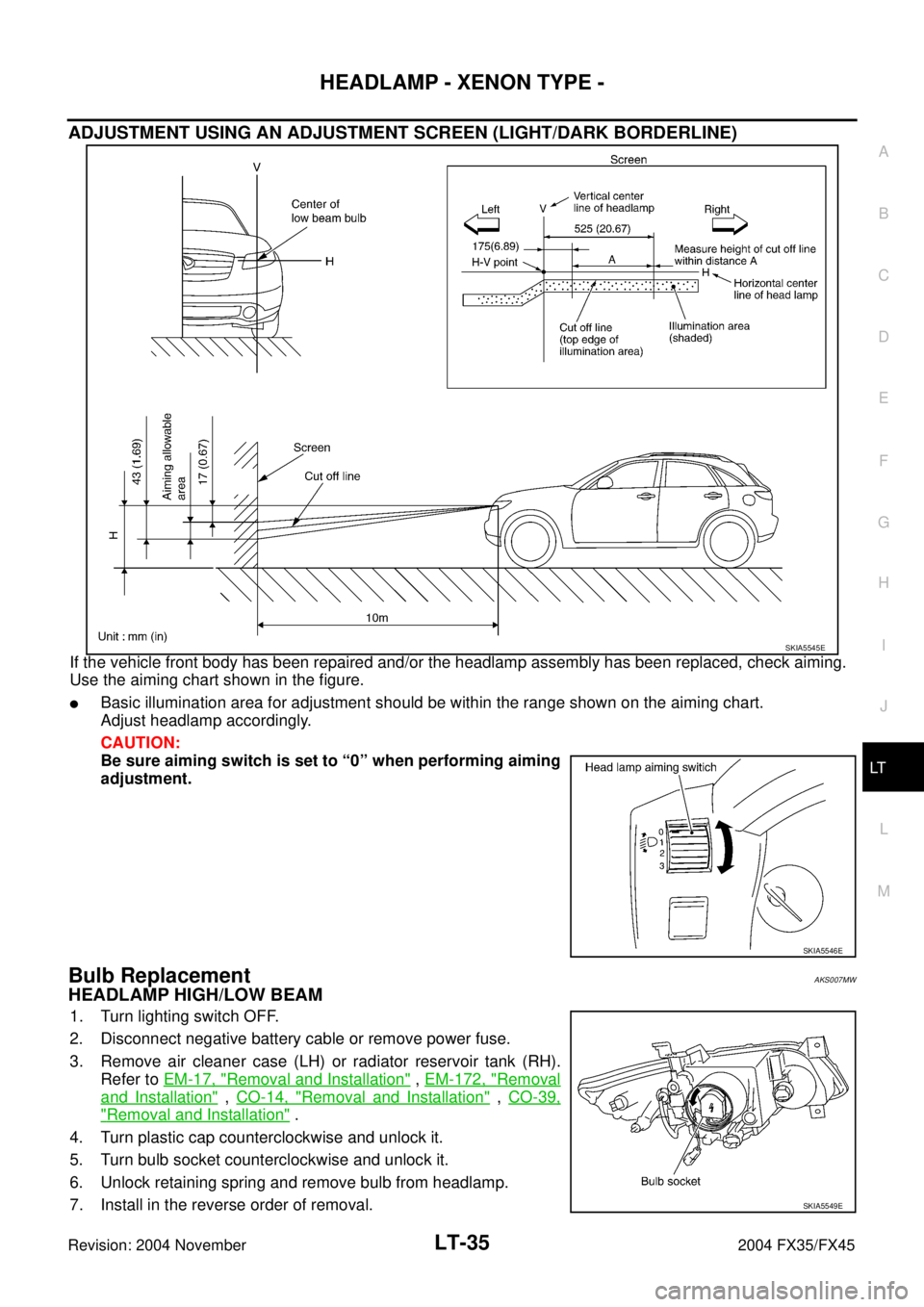
ADJUSTMENT USING AN ADJUSTMENT SCREEN (LIGHT/DARK BORDERLINE)
If the vehicle front body has been repaired and/or the headlamp assembly has been replaced, check aiming.
Use the aiming chart shown in the figure.
�Basic illumination area for adjustment should be within the range shown on the aiming chart.
Adjust headlamp accordingly.
CAUTION:
Be sure aiming switch is set to “0” when performing aiming
adjustment.
Bulb ReplacementAKS007MW
HEADLAMP HIGH/LOW BEAM
1. Turn lighting switch OFF.
2. Disconnect negative battery cable or remove power fuse.
3. Remove air cleaner case (LH) or radiator reservoir tank (RH).
Refer to EM-17, "
Removal and Installation" , EM-172, "Removal
and Installation" , CO-14, "Removal and Installation" , CO-39,
"Removal and Installation" .
4. Turn plastic cap counterclockwise and unlock it.
5. Turn bulb socket counterclockwise and unlock it.
6. Unlock retaining spring and remove bulb from headlamp.
7. Install in the reverse order of removal.
SKIA5545E
SKIA5546E
SKIA5549E
Page 3591 of 4449
LT-36
HEADLAMP - XENON TYPE -
Revision: 2004 November 2004 FX35/FX45
NOTE:
After installation, perform aiming adjustment. Refer to LT- 3 4 , "
Aiming Adjustment" .
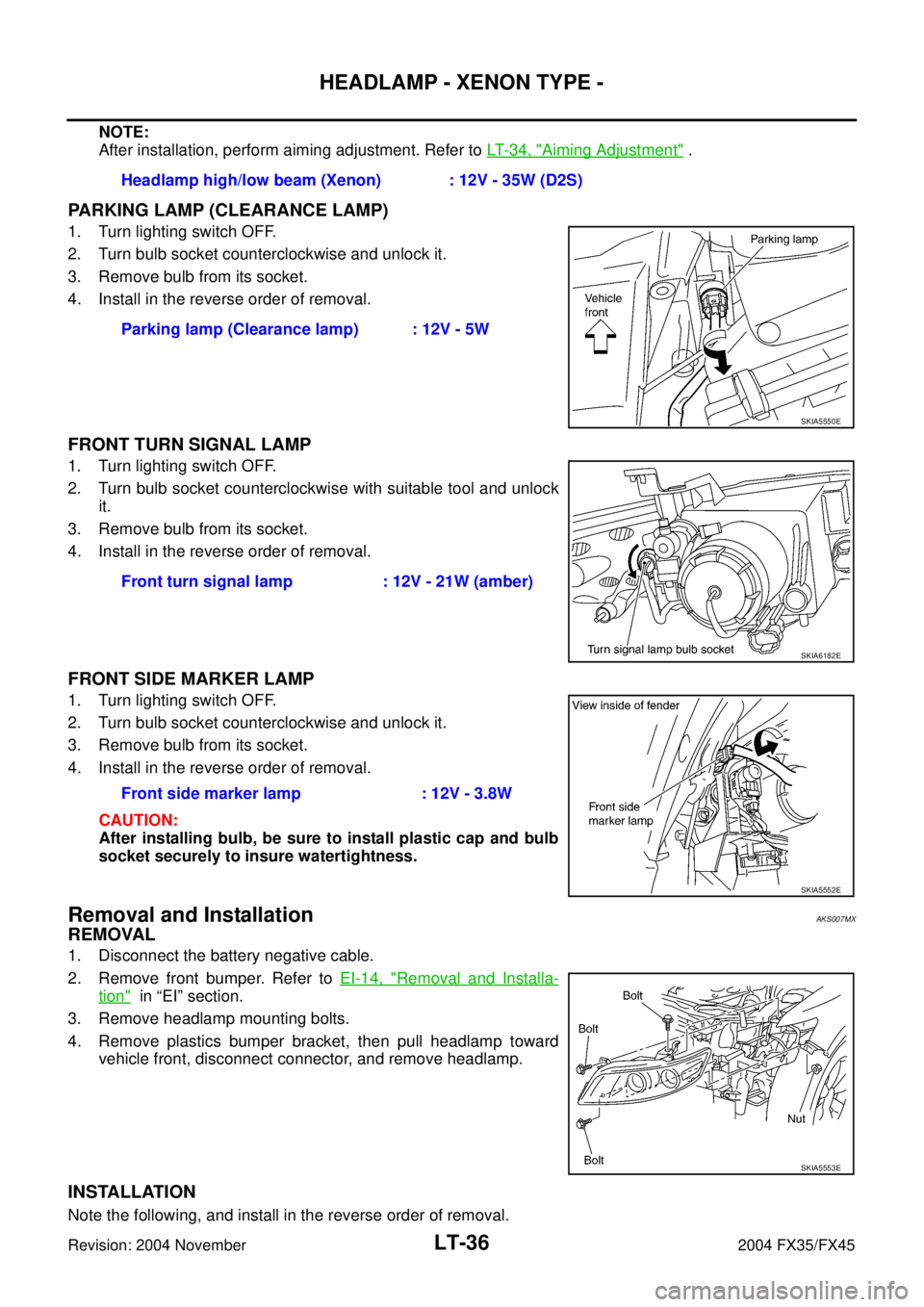
PARKING LAMP (CLEARANCE LAMP)
1. Turn lighting switch OFF.
2. Turn bulb socket counterclockwise and unlock it.
3. Remove bulb from its socket.
4. Install in the reverse order of removal.
FRONT TURN SIGNAL LAMP
1. Turn lighting switch OFF.
2. Turn bulb socket counterclockwise with suitable tool and unlock
it.
3. Remove bulb from its socket.
4. Install in the reverse order of removal.
FRONT SIDE MARKER LAMP
1. Turn lighting switch OFF.
2. Turn bulb socket counterclockwise and unlock it.
3. Remove bulb from its socket.
4. Install in the reverse order of removal.
CAUTION:
After installing bulb, be sure to install plastic cap and bulb
socket securely to insure watertightness.
Removal and InstallationAKS007MX
REMOVAL
1. Disconnect the battery negative cable.
2. Remove front bumper. Refer to EI-14, "
Removal and Installa-
tion" in “EI” section.
3. Remove headlamp mounting bolts.
4. Remove plastics bumper bracket, then pull headlamp toward
vehicle front, disconnect connector, and remove headlamp.
INSTALLATION
Note the following, and install in the reverse order of removal. Headlamp high/low beam (Xenon) : 12V - 35W (D2S)
Parking lamp (Clearance lamp) : 12V - 5W
SKIA5550E
Front turn signal lamp : 12V - 21W (amber)
SKIA6182E
Front side marker lamp : 12V - 3.8W
SKIA5552E
SKIA5553E
Page 3601 of 4449
LT-46
DAYTIME LIGHT SYSTEM
Revision: 2004 November 2004 FX35/FX45
How to Proceed With Trouble DiagnosisAKS007N6
1. Confirm the symptom or customer complaint.
2. Understand operation description and function description. Refer to LT- 3 8 , "
System Description" .
3. Perform the Preliminary Check. Refer to LT- 4 6 , "
Preliminary Check" .
4. Check symptom and repair or replace the cause of malfunction.
5. Does the headlamp operate normally? If YES: GO TO 6. If NO: GO TO 4.
6. INSPECTION END
Preliminary CheckAKS007N7
CHECK POWER SUPPLY AND GROUND CIRCUIT
1. CHECK FUSES
�Check fuses for blown-out.
Refer to LT- 4 1 , "Wiring Diagram — DTRL —" .
OK or NG
OK >> GO TO 2.
NG >> If fuse is blown, be sure to eliminate cause of malfunction before installing new fuse. Refer to PG-
3, "POWER SUPPLY ROUTING CIRCUIT" .
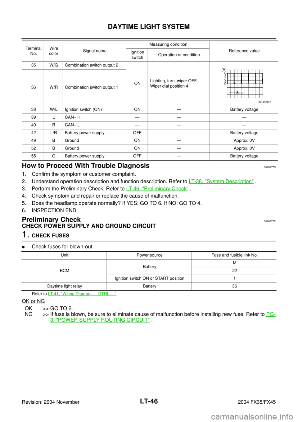
35 W/G Combination switch output 2
ONLighting, turn, wiper OFF
Wiper dial position 4
36 W/R Combination switch output 1
38 W/L Ignition switch (ON) ON — Battery voltage
39 L CAN− H—— —
40 R CAN− L—— —
42 L/R Battery power supply OFF — Battery voltage
49 B Ground ON — Approx. 0V
52 B Ground ON — Approx. 0V
55 G Battery power supply OFF — Battery voltage Terminal
No.Wire
colorSignal nameMeasuring condition
Reference value
Ignition
switchOperation or condition
SKIA5292E
Unit Power source Fuse and fusible link No.
BCMBatteryM
22
Ignition switch ON or START position 1
Daytime light relay Battery 36
Page 3602 of 4449
DAYTIME LIGHT SYSTEM
LT-47
C
D
E
F
G
H
I
J
L
MA
B
LT
Revision: 2004 November 2004 FX35/FX45
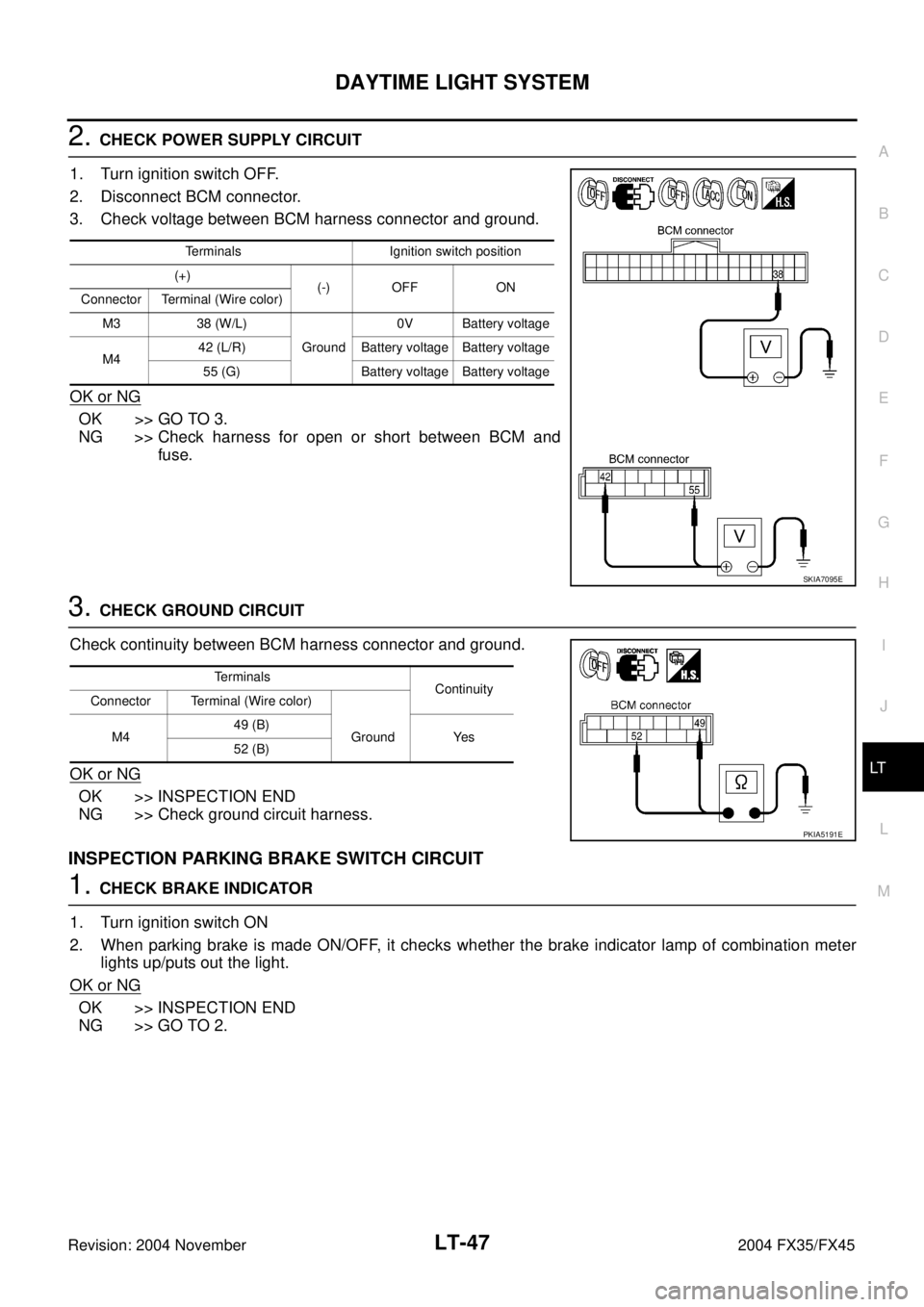
2. CHECK POWER SUPPLY CIRCUIT
1. Turn ignition switch OFF.
2. Disconnect BCM connector.
3. Check voltage between BCM harness connector and ground.
OK or NG
OK >> GO TO 3.
NG >> Check harness for open or short between BCM and
fuse.
3. CHECK GROUND CIRCUIT
Check continuity between BCM harness connector and ground.
OK or NG
OK >> INSPECTION END
NG >> Check ground circuit harness.
INSPECTION PARKING BRAKE SWITCH CIRCUIT
1. CHECK BRAKE INDICATOR
1. Turn ignition switch ON
2. When parking brake is made ON/OFF, it checks whether the brake indicator lamp of combination meter
lights up/puts out the light.
OK or NG
OK >> INSPECTION END
NG >> GO TO 2.
Terminals Ignition switch position
(+)
(-) OFF ON
Connector Terminal (Wire color)
M3 38 (W/L)
Ground0V Battery voltage
M442 (L/R) Battery voltage Battery voltage
55 (G) Battery voltage Battery voltage
SKIA7095E
Terminals
Continuity
Connector Terminal (Wire color)
M449 (B)
Ground Yes
52 (B)
PKIA5191E
Page 3603 of 4449
LT-48
DAYTIME LIGHT SYSTEM
Revision: 2004 November 2004 FX35/FX45
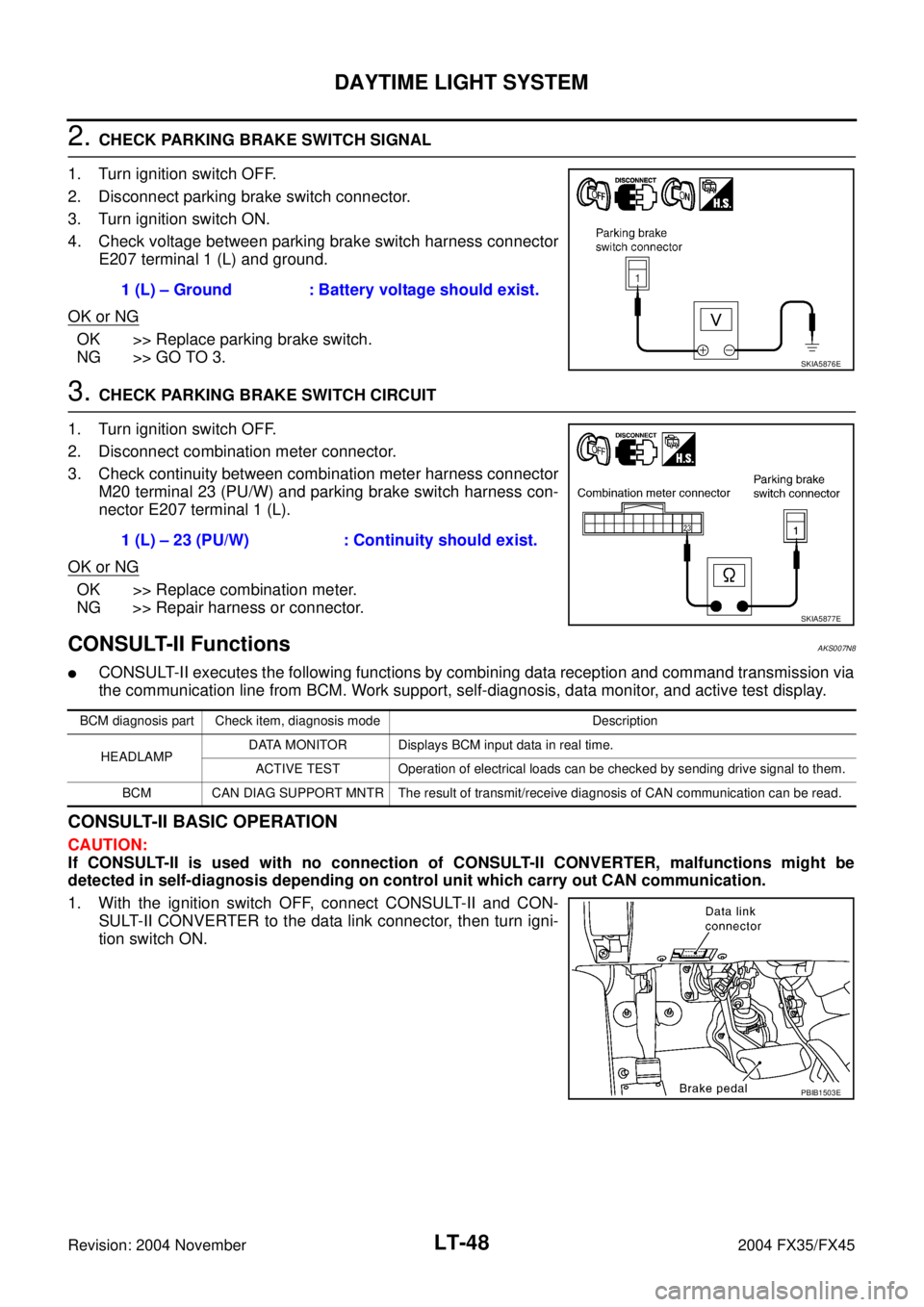
2. CHECK PARKING BRAKE SWITCH SIGNAL
1. Turn ignition switch OFF.
2. Disconnect parking brake switch connector.
3. Turn ignition switch ON.
4. Check voltage between parking brake switch harness connector
E207 terminal 1 (L) and ground.
OK or NG
OK >> Replace parking brake switch.
NG >> GO TO 3.
3. CHECK PARKING BRAKE SWITCH CIRCUIT
1. Turn ignition switch OFF.
2. Disconnect combination meter connector.
3. Check continuity between combination meter harness connector
M20 terminal 23 (PU/W) and parking brake switch harness con-
nector E207 terminal 1 (L).
OK or NG
OK >> Replace combination meter.
NG >> Repair harness or connector.
CONSULT-II Functions AKS007N8
�CONSULT-II executes the following functions by combining data reception and command transmission via
the communication line from BCM. Work support, self-diagnosis, data monitor, and active test display.
CONSULT-II BASIC OPERATION
CAUTION:
If CONSULT-II is used with no connection of CONSULT-II CONVERTER, malfunctions might be
detected in self-diagnosis depending on control unit which carry out CAN communication.
1. With the ignition switch OFF, connect CONSULT-II and CON-
SULT-II CONVERTER to the data link connector, then turn igni-
tion switch ON.1 (L) – Ground : Battery voltage should exist.
SKIA5876E
1 (L) – 23 (PU/W) : Continuity should exist.
SKIA5877E
BCM diagnosis part Check item, diagnosis mode Description
HEADLAMPDATA MONITOR Displays BCM input data in real time.
ACTIVE TEST Operation of electrical loads can be checked by sending drive signal to them.
BCM CAN DIAG SUPPORT MNTR The result of transmit/receive diagnosis of CAN communication can be read.
PBIB1503E