Page 3828 of 4449

PB-1
PARKING BRAKE SYSTEM
F BRAKES
CONTENTS
C
D
E
G
H
I
J
K
L
M
SECTION PB
A
B
PB
Revision: 2004 November 2004 FX35/FX45
PARKING BRAKE SYSTEM
PARKING BRAKE SYSTEM ...................................... 2
On-Vehicle Service ................................................... 2
PEDAL STROKE ................................................... 2
INSPECT COMPONENTS .................................... 2
ADJUSTMENT ...................................................... 2
PARKING BRAKE CONTROL ................................... 3
Components ............................................................. 3
Removal and Installation .......................................... 3
REMOVAL ............................................................. 3
INSTALLATION ..................................................... 4PARKING BRAKE SHOE ........................................... 5
Components ............................................................. 5
Removal and Installation .......................................... 5
REMOVAL ............................................................. 5
INSPECTION AFTER REMOVAL ......................... 6
INSTALLATION ..................................................... 6
SERVICE DATA AND SPECIFICATIONS (SDS) ........ 7
Parking Drum Brake ................................................. 7
Parking Brake Control .............................................. 7
Page 3829 of 4449

PB-2
PARKING BRAKE SYSTEM
Revision: 2004 November 2004 FX35/FX45
PARKING BRAKE SYSTEMPFP:36010
On-Vehicle ServiceAFS001TJ
PEDAL STROKE
�When parking brake pedal is operated with a force of 200 N (20.4 kg, 44.9 lb), make sure the stroke is
within the specified number of notches. (Check it by listening and counting the ratchet clicks.)
INSPECT COMPONENTS
�Make sure the components are attached properly (check for looseness, backlash, etc.).
�Check parking brake pedal assembly for bend, damage and cracks, and replace if necessary.
�Check cable for wear and damage, and replace if necessary.
�Check parking brake warning lamp switch for malfunction, and replace if necessary.
ADJUSTMENT
�To perform adjustment operations, remove tire from the vehicle with power tool.
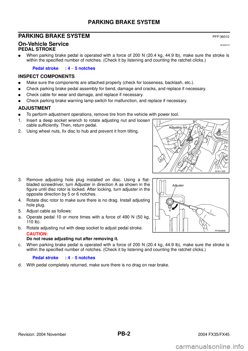
1. Insert a deep socket wrench to rotate adjusting nut and loosen
cable sufficiently. Then, return pedal.
2. Using wheel nuts, fix disc to hub and prevent it from tilting.
3. Remove adjusting hole plug installed on disc. Using a flat-
bladed screwdriver, turn Adjuster in direction A as shown in the
figure until disc rotor is locked. After locking, turn adjuster in the
opposite direction by 5 or 6 notches.
4. Rotate disc rotor to make sure there is no drag. Install adjusting
hole plug.
5. Adjust cable as follows:
a. Operate pedal 10 or more times with a force of 490 N (50 kg,
11 0 l b ) .
b. Rotate adjusting nut with deep socket to adjust pedal stroke.
CAUTION:
Do not reuse adjusting nut after removing it.
c. When parking brake pedal is operated with a force of 200 N (20.4 kg, 44.9 lb), make sure the stroke is
within the specified number of notches. (Check it by listening and counting the ratchet clicks.)
d. With pedal completely returned, make sure there is no drag on rear brake.Pedal stroke : 4 − 5 notches
SFIA1139E
Pedal stroke : 4 − 5 notches
PFIA0295E
Page 3834 of 4449
SERVICE DATA AND SPECIFICATIONS (SDS)
PB-7
C
D
E
G
H
I
J
K
L
MA
B
PB
Revision: 2004 November 2004 FX35/FX45
SERVICE DATA AND SPECIFICATIONS (SDS)PFP:00030
Parking Drum Brake AFS001TO
Parking Brake ControlAFS001TP
TypeDS19HC
Brake liningStandard thickness (new) 3.2 mm (0.126 in)
Wear limit thickness 1.5 mm (0.059 in)
Drum (disc)Standard inner diameter (new) 190 mm (7.48 in)
Wear limit of inner diameter 191 mm (7.52 in)
Control typeFoot pedal
Number of notches [under force of 200 N (20.4 kg, 44.9 lb)] 4 − 5 notches
Number of notches
when warning lamp switch comes on1 notches
Page 3835 of 4449
PB-8
SERVICE DATA AND SPECIFICATIONS (SDS)
Revision: 2004 November 2004 FX35/FX45
Page 3920 of 4449

PR-1
PROPELLER SHAFT
D DRIVELINE/AXLE
CONTENTS
C
E
F
G
H
I
J
K
L
M
SECTION PR
A
B
PR
Revision: 2004 November 2004 FX35/FX45
PROPELLER SHAFT
PREPARATION ........................................................... 2
Special Service Tools ............................................... 2
Commercial Service Tools ........................................ 2
NOISE, VIBRATION AND HARSHNESS (NVH)
TROUBLESHOOTING ................................................ 3
NVH Troubleshooting Chart ..................................... 3
FRONT PROPELLER SHAFT .................................... 4
On-Vehicle Service ................................................... 4
PROPELLER SHAFT VIBRATION ........................ 4
APPEARANCE CHECKING .................................. 4
Removal and Installation .......................................... 4
REMOVAL ............................................................. 4
INSPECTION ........................................................ 5
INSTALLATION ..................................................... 5
REAR PROPELLER SHAFT ...................................... 6
Service Information .................................................. 6
On-Vehicle Service ................................................... 6
PROPELLER SHAFT VIBRATION ........................ 6APPEARANCE AND NOISE INSPECTION .......... 6
Removal and Installation .......................................... 7
REMOVAL ............................................................. 8
INSPECTION ........................................................ 8
INSTALLATION ................................................... 10
Disassembly and Assembly .................................... 11
DISASSEMBLY ................................................... 11
ASSEMBLY ......................................................... 12
SERVICE DATA AND SPECIFICATIONS (SDS) ...... 14
General Specifications ............................................ 14
2WD MODEL ....................................................... 14
AWD MODEL ...................................................... 14
Front Propeller Shaft .............................................. 14
JOURNAL AXIAL PLAY ....................................... 14
PROPELLER SHAFT RUNOUT LIMIT ................ 14
Rear Propeller Shaft ............................................... 14
JOURNAL AXIAL PLAY ....................................... 14
PROPELLER SHAFT RUNOUT LIMIT ................ 14
Page 3921 of 4449
PR-2
PREPARATION
Revision: 2004 November 2004 FX35/FX45
PREPARATIONPFP:00002
Special Service ToolsADS000KJ
The actual shapes of Kent-Moore tools may differ from those of special service tools illustrated here.
Commercial Service ToolsADS000KC
Tool number
(Kent-Moore No.)
Tool nameDescription
KV40104000
(—)
Flange wrench
a: 85 mm (3.35 in)
b: 65 mm (2.56 in)Removing and installing center flange lock nut
ST30031000
(J-22912-01)
Puller
a: 90 mm (3.54 in) dia.
b: 50 mm (1.97 in) dia.Removing rear propeller shaft center bearing
NT659
NT411
Tool nameDescription
Power toolLoosening bolts and nuts
PBIC0190E
Page 3923 of 4449

PR-4
FRONT PROPELLER SHAFT
Revision: 2004 November 2004 FX35/FX45
FRONT PROPELLER SHAFTPFP:37200
On-Vehicle ServiceADS000KL
PROPELLER SHAFT VIBRATION
If vibration is present at high speed, inspect propeller shaft runout first.
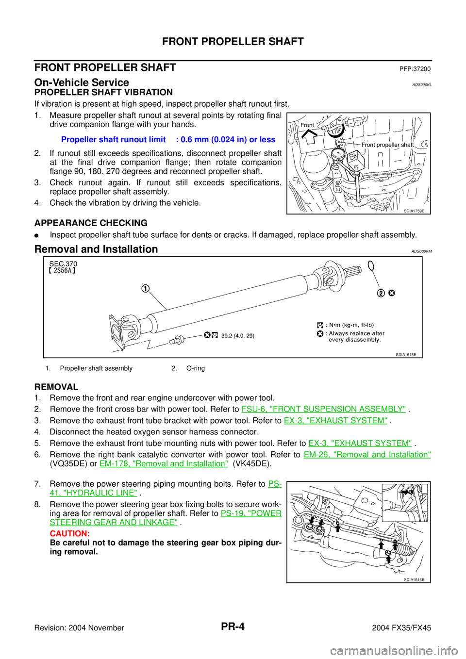
1. Measure propeller shaft runout at several points by rotating final
drive companion flange with your hands.
2. If runout still exceeds specifications, disconnect propeller shaft
at the final drive companion flange; then rotate companion
flange 90, 180, 270 degrees and reconnect propeller shaft.
3. Check runout again. If runout still exceeds specifications,
replace propeller shaft assembly.
4. Check the vibration by driving the vehicle.
APPEARANCE CHECKING
�Inspect propeller shaft tube surface for dents or cracks. If damaged, replace propeller shaft assembly.
Removal and InstallationADS000KM
REMOVAL
1. Remove the front and rear engine undercover with power tool.
2. Remove the front cross bar with power tool. Refer to FSU-6, "
FRONT SUSPENSION ASSEMBLY" .
3. Remove the exhaust front tube bracket with power tool. Refer to EX-3, "
EXHAUST SYSTEM" .
4. Disconnect the heated oxygen sensor harness connector.
5. Remove the exhaust front tube mounting nuts with power tool. Refer to EX-3, "
EXHAUST SYSTEM" .
6. Remove the right bank catalytic converter with power tool. Refer to EM-26, "
Removal and Installation"
(VQ35DE) or EM-178, "Removal and Installation" (VK45DE).
7. Remove the power steering piping mounting bolts. Refer to PS-
41, "HYDRAULIC LINE" .
8. Remove the power steering gear box fixing bolts to secure work-
ing area for removal of propeller shaft. Refer to PS-19, "
POWER
STEERING GEAR AND LINKAGE" .
CAUTION:
Be careful not to damage the steering gear box piping dur-
ing removal.Propeller shaft runout limit : 0.6 mm (0.024 in) or less
SDIA1759E
SDIA1515E
1. Propeller shaft assembly 2. O-ring
SDIA1516E
Page 3925 of 4449

PR-6
REAR PROPELLER SHAFT
Revision: 2004 November 2004 FX35/FX45
REAR PROPELLER SHAFTPFP:37000
Service InformationADS000KK
Do not support the rear cover (aluminium), when supporting the gear carrier with a transmission jack.
On-Vehicle ServiceADS000KE
PROPELLER SHAFT VIBRATION
CAUTION:
If vibration is present at high speed, check mounting between propeller shaft and companion flange.
If vibration is present at high speed, check propeller shaft runout first.
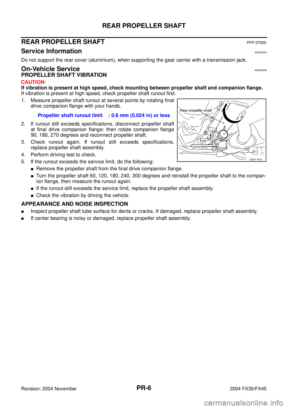
1. Measure propeller shaft runout at several points by rotating final
drive companion flange with your hands.
2. If runout still exceeds specifications, disconnect propeller shaft
at final drive companion flange: then rotate companion flange
90, 180, 270 degrees and reconnect propeller shaft.
3. Check runout again. If runout still exceeds specifications,
replace propeller shaft assembly.
4. Perform driving test to check.
5. If the runout exceeds the service limit, do the following:
�Remove the propeller shaft from the final drive companion flange.
�Turn the propeller shaft 60, 120, 180, 240, 300 degrees and reinstall the propeller shaft to the compan-
ion flange, then measure the runout again.
�If the runout still exceeds the service limit, replace the propeller shaft assembly.
�Check the vibration by driving the vehicle.
APPEARANCE AND NOISE INSPECTION
�Inspect propeller shaft tube surface for dents or cracks. If damaged, replace propeller shaft assembly.
�If center bearing is noisy or damaged, replace propeller shaft assembly.Propeller shaft runout limit : 0.6 mm (0.024 in) or less
SDIA1781E