Page 1975 of 4449
![INFINITI FX35 2004 Service Manual EC-634
[VQ35DE]
ASCD INDICATOR
Revision: 2004 November 2004 FX35/FX45
Diagnostic ProcedureABS006Z5
1. CHECK OVERALL FUNCTION
Check ASCD indicator under the following conditions.
OK or NG
OK >>INSPECTI](/manual-img/42/57021/w960_57021-1974.png "INFINITI FX35 2004 Service Manual EC-634
[VQ35DE]
ASCD INDICATOR
Revision: 2004 November 2004 FX35/FX45
Diagnostic ProcedureABS006Z5
1. CHECK OVERALL FUNCTION
Check ASCD indicator under the following conditions.
OK or NG
OK >>INSPECTI")
EC-634
[VQ35DE]
ASCD INDICATOR
Revision: 2004 November 2004 FX35/FX45
Diagnostic ProcedureABS006Z5
1. CHECK OVERALL FUNCTION
Check ASCD indicator under the following conditions.
OK or NG
OK >>INSPECTION END
NG >> GO TO 2.
2. CHECK DTC
Check that DTC U1000 or U1001 is not displayed.
OK or NG
OK >> GO TO 3.
NG >> Perform trouble diagnoses for DTC U1000, U1001. Refer to EC-142, "
DTC U1000, U1001 CAN
COMMUNICATION LINE" .
3. CHECK DTC WITH “UNIFIED METER AND A/C AMP.”
Refer to DI-32, "
SELF-DIAGNOSTIC RESULTS" .
OK or NG
OK >> GO TO 4.
NG >> Go to DI-22, "
Communication Line Inspection" .
4. CHECK INTERMITTENT INCIDENT
Refer to EC-135, "
TROUBLE DIAGNOSIS FOR INTERMITTENT INCIDENT" .
>>INSPECTION END
ASCD INDICATOR CONDITION SPECIFICATION
CRUISE LAMP
�Ignition switch: ON�ON/OFF(MAIN) switch: pressed
at the 1st time → at the 2nd timeON → OFF
SET LAMP
�ON/OFF(MAIN) switch: ON
�When vehicle speed is
between 40 km/h (25 MPH)
and 144 km/h (89 MPH)
�ASCD is operating ON
�ASCD is not operating OFF
Page 1976 of 4449
![INFINITI FX35 2004 Service Manual SNOW MODE SWITCH
EC-635
[VQ35DE]
C
D
E
F
G
H
I
J
K
L
MA
EC
Revision: 2004 November 2004 FX35/FX45
SNOW MODE SWITCHPFP:25310
DescriptionABS00A2B
NOTE:
If DTC U1000 or U1001 are displayed, first perform](/manual-img/42/57021/w960_57021-1975.png "INFINITI FX35 2004 Service Manual SNOW MODE SWITCH
EC-635
[VQ35DE]
C
D
E
F
G
H
I
J
K
L
MA
EC
Revision: 2004 November 2004 FX35/FX45
SNOW MODE SWITCHPFP:25310
DescriptionABS00A2B
NOTE:
If DTC U1000 or U1001 are displayed, first perform")
SNOW MODE SWITCH
EC-635
[VQ35DE]
C
D
E
F
G
H
I
J
K
L
MA
EC
Revision: 2004 November 2004 FX35/FX45
SNOW MODE SWITCHPFP:25310
DescriptionABS00A2B
NOTE:
If DTC U1000 or U1001 are displayed, first perform the trouble diagnosis for DTC U1000, U1001.
Refer to EC-142, "
DTC U1000, U1001 CAN COMMUNICATION LINE" .
The snow mode switch signal is sent to the “unified meter and A/C amp.” from the snow mode switch. The
“unified meter and A/C amp.” then sends the signal to the ECM by CAN communication line.
The snow mode is used for driving or starting the vehicle on snowy roads or slippery areas. If the snow mode
is activated, the vehicle speed will not be accelerated immediately than your original pedal in due to avoid the
vehicle slip. In other words, ECM controls the rapid engine torque change by controlling the electric throttle
control actuator operating speed.
CONSULT-II Reference Value in the Data Monitor ModeABS00A2C
MONITOR ITEM CONDITION SPECIFICATION
SNOW MODE SW
�Ignition switch: ONSNOW MODE SW: ON ON
SNOW MODE SW: OFF OFF
Page 1989 of 4449
EC-648
[VQ35DE]
EVAPORATIVE EMISSION SYSTEM
Revision: 2004 November 2004 FX35/FX45
WITH CONSULT-II
1. Attach the EVAP service port adapter securely to the EVAP service port.
2. Also attach the pressure pump and hose to the EVAP service port adapter.
3. Turn ignition switch ON.
4. Select the “EVAP SYSTEM CLOSE” of “WORK SUPPORT
MODE” with CONSULT-II.
5. Touch “START”. A bar graph (Pressure indicating display) will
appear on the screen.
6. Apply positive pressure to the EVAP system until the pressure
indicator reaches the middle of the bar graph.
7. Remove EVAP service port adapter and hose with pressure
pump.
8. Locate the leak using a leak detector. Refer to EC-644, "
EVAP-
ORATIVE EMISSION LINE DRAWING" .
WITHOUT CONSULT-II
1. Attach the EVAP service port adapter securely to the EVAP ser-
vice port.
2. Also attach the pressure pump with pressure gauge to the EVAP
service port adapter.
PEF838U
PEF917U
SEF200U
SEF462UA
Page 2003 of 4449
![INFINITI FX35 2004 Service Manual EC-662
[VK45DE]
INDEX FOR DTC
Revision: 2004 November 2004 FX35/FX45
[VK45DE]INDEX FOR DTCPFP:00024
Alphabetical IndexABS00BYV
NOTE:
If DTC U1000 or U1001 is displayed with other DTC, first perform th](/manual-img/42/57021/w960_57021-2002.png "INFINITI FX35 2004 Service Manual EC-662
[VK45DE]
INDEX FOR DTC
Revision: 2004 November 2004 FX35/FX45
[VK45DE]INDEX FOR DTCPFP:00024
Alphabetical IndexABS00BYV
NOTE:
If DTC U1000 or U1001 is displayed with other DTC, first perform th")
EC-662
[VK45DE]
INDEX FOR DTC
Revision: 2004 November 2004 FX35/FX45
[VK45DE]INDEX FOR DTCPFP:00024
Alphabetical IndexABS00BYV
NOTE:
If DTC U1000 or U1001 is displayed with other DTC, first perform the trouble diagnosis for DTC U1000,
U1001. Refer to EC-792, "
DTC U1000, U1001 CAN COMMUNICATION LINE" .
×:Applicable —: Not applicable
Items
(CONSULT-II screen terms)DTC*
1
TripMIL lighting
upReference page
CONSULT-II
GST*
2ECM*3
A/T INTERLOCK P1730 1730 1×AT-147
A/T TCC S/V FNCTN P0744 0744 2×AT-125
ACC COMMAND VALUE*7P1568 1568 1×EC-1188
APP SEN 1/CIRC P2122 2122 1×EC-1225
APP SEN 1/CIRC P2123 2123 1×EC-1225
APP SEN 2/CIRC P2127 2127 1×EC-1232
APP SEN 2/CIRC P2128 2128 1×EC-1232
APP SENSOR P2138 2138 1×EC-1246
ASCD BRAKE SW*7 *8P1572 1572 1 —EC-1189,
EC-1199
ASCD SW*7 *8P1564 1564 1 —EC-1174,
EC-1181
ASCD VHL SPD SEN*7 *8P1574 1574 1 —EC-1207,
EC-1209
ATF TEMP SEN/CIRC P0710 0710 2×AT-139
BRAKE SW/CIRCUIT P1805 1805 2 —EC-1220
CAN COMM CIRCUIT U1000
1000*51× or —EC-792
CAN COMM CIRCUIT U1001
1001*52—EC-792
CKP SEN/CIRCUIT P0335 0335 2×EC-960
CLOSED LOOP-B1 P1148 1148 1×EC-1138
CLOSED LOOP-B2 P1168 1168 1×EC-1138
CMP SEN/CIRC-B1 P0340 0340 2×EC-966
CTP LEARNING P1225 1225 2 —EC-1152
CTP LEARNING P1226 1226 2 —EC-1154
CYL 1 MISFIRE P0301 0301 2×EC-949
CYL 2 MISFIRE P0302 0302 2×EC-949
CYL 3 MISFIRE P0303 0303 2×EC-949
CYL 4 MISFIRE P0304 0304 2×EC-949
CYL 5 MISFIRE P0305 0305 2×EC-949
CYL 6 MISFIRE P0306 0306 2×EC-949
CYL 7 MISFIRE P0307 0307 2×EC-949
CYL 8 MISFIRE P0308 0308 2×EC-949
D/C SOLENOID/CIRC P1762 1762 1×AT-160
D/C SOLENOID FNCTN P1764 1764 1×AT-162
ECM P0605 0605 1 or 2× or —EC-1057
ECM BACK UP/CIRCUIT P1065 1065 2×EC-1060
ECT SEN/CIRCUIT P0117 0117 1×EC-842
Page 2006 of 4449
![INFINITI FX35 2004 Service Manual INDEX FOR DTC
EC-665
[VK45DE]
C
D
E
F
G
H
I
J
K
L
MA
EC
Revision: 2004 November 2004 FX35/FX45
*1: 1st trip DTC No. is the same as DTC No.
*2: This number is prescribed by SAE J2012.
*3: In Diagnostic](/manual-img/42/57021/w960_57021-2005.png "INFINITI FX35 2004 Service Manual INDEX FOR DTC
EC-665
[VK45DE]
C
D
E
F
G
H
I
J
K
L
MA
EC
Revision: 2004 November 2004 FX35/FX45
*1: 1st trip DTC No. is the same as DTC No.
*2: This number is prescribed by SAE J2012.
*3: In Diagnostic")
INDEX FOR DTC
EC-665
[VK45DE]
C
D
E
F
G
H
I
J
K
L
MA
EC
Revision: 2004 November 2004 FX35/FX45
*1: 1st trip DTC No. is the same as DTC No.
*2: This number is prescribed by SAE J2012.
*3: In Diagnostic Test Mode II (Self-diagnostic results). This number is controlled by NISSAN.
*4: When engine is running.
*5: The troubleshooting for this DTC needs CONSULT-II.
*6: When the fail-safe operations for both self-diagnoses occur at the same time, the MIL illuminates.
*7: Models with ICC
*8: Models with ASCD
DTC No. IndexABS00BYW
NOTE:
If DTC U1000 or U1001 is displayed with other DTC, first perform the trouble diagnosis for DTC U1000,
U1001. Refer to EC-792, "
DTC U1000, U1001 CAN COMMUNICATION LINE" .
NO DTC IS DETECTED.
FURTHER TESTING
MAY BE REQUIRED.P0000 0000———
P-N POS SW/CIRCUIT P1706 1706 2×EC-1211
PNP SW/CIRC P0705 0705 2×AT- 11 2
PURG VOLUME CONT/V P0444 0444 2×EC-990
PURG VOLUME CONT/V P0445 0445 2×EC-990
PURG VOLUME CONT/V P1444 1444 2×EC-1160
PW ST P SEN/CIRC P0550 0550 2 —EC-1052
SENSOR POWER/CIRC P1229 1229 1×EC-1156
SHIFT SIG FNCTN P1780 1780 2 —EC-1218
TCC SOLENOID/CIRC P0740 0740 2×AT- 1 2 3
TCS C/U FUNCTN P1211 1211 2 —EC-1140
TCS/CIRC P1212 1212 2 —EC-1141
THERMSTAT FNCTN P0128 0128 2×EC-861
TP SEN 1/CIRC P0222 0222 1×EC-942
TP SEN 1/CIRC P0223 0223 1×EC-942
TP SEN 2/CIRC P0122 0122 1×EC-848
TP SEN 2/CIRC P0123 0123 1×EC-848
TP SENSOR P2135 2135 1×EC-1239
TURBINE REV S/CIRC P1716 1716 2×AT- 1 4 3
TW CATALYST SYS-B1 P0420 0420 2×EC-971
TW CATALYST SYS-B2 P0430 0430 2×EC-971
V/SP SEN(A/T OUT) P1720 1720 2 —EC-1216
VEH SPD SEN/CIR AT*6P0720 0720 2×AT- 11 6
VEH SPEED SEN/CIRC*6P0500 0500 2×EC-1046
VENT CONTROL VALVE P0447 0447 2×EC-997
VENT CONTROL VALVE P1446 1446 2×EC-1168
Items
(CONSULT-II screen terms)DTC*
1
TripMIL lighting
upReference page
CONSULT-II
GST*
2ECM*3
Page 2013 of 4449
EC-672
[VK45DE]
PRECAUTIONS
Revision: 2004 November 2004 FX35/FX45
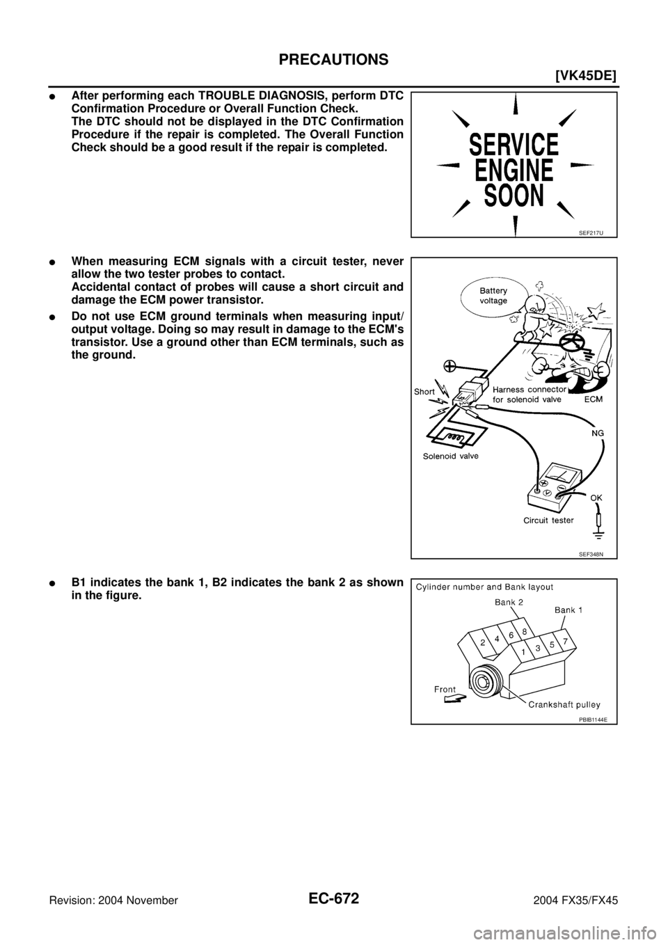
�After performing each TROUBLE DIAGNOSIS, perform DTC
Confirmation Procedure or Overall Function Check.
The DTC should not be displayed in the DTC Confirmation
Procedure if the repair is completed. The Overall Function
Check should be a good result if the repair is completed.
�When measuring ECM signals with a circuit tester, never
allow the two tester probes to contact.
Accidental contact of probes will cause a short circuit and
damage the ECM power transistor.
�Do not use ECM ground terminals when measuring input/
output voltage. Doing so may result in damage to the ECM's
transistor. Use a ground other than ECM terminals, such as
the ground.
�B1 indicates the bank 1, B2 indicates the bank 2 as shown
in the figure.
SEF217U
SEF348N
PBIB1144E
Page 2030 of 4449
![INFINITI FX35 2004 Service Manual BASIC SERVICE PROCEDURE
EC-689
[VK45DE]
C
D
E
F
G
H
I
J
K
L
MA
EC
Revision: 2004 November 2004 FX35/FX45
INSPECTION PROCEDURE
1. INSPECTION START
1. Check service records for any recent repairs that m](/manual-img/42/57021/w960_57021-2029.png "INFINITI FX35 2004 Service Manual BASIC SERVICE PROCEDURE
EC-689
[VK45DE]
C
D
E
F
G
H
I
J
K
L
MA
EC
Revision: 2004 November 2004 FX35/FX45
INSPECTION PROCEDURE
1. INSPECTION START
1. Check service records for any recent repairs that m")
BASIC SERVICE PROCEDURE
EC-689
[VK45DE]
C
D
E
F
G
H
I
J
K
L
MA
EC
Revision: 2004 November 2004 FX35/FX45
INSPECTION PROCEDURE
1. INSPECTION START
1. Check service records for any recent repairs that may indicate a related malfunction, or a current need for
scheduled maintenance.
2. Open engine hood and check the following:
–Harness connectors for improper connections
–Wiring harness for improper connections, pinches and cut
–Vacuum hoses for splits, kinks and improper connections
–Hoses and ducts for leaks
–Air cleaner clogging
–Gasket
3. Confirm that electrical or mechanical loads are not applied.
–Headlamp switch is OFF.
–Air conditioner switch is OFF.
–Rear window defogger switch is OFF.
–Steering wheel is in the straight-ahead position, etc.
4. Start engine and warm it up until engine coolant temperature
indicator points the middle of gauge.
Ensure engine stays below 1,000 rpm.
5. Run engine at about 2,000 rpm for about 2 minutes under no
load.
6. Make sure that no DTC is displayed with CONSULT-II or GST.
OK or NG
OK >> GO TO 3.
NG >> GO TO 2.
2. REPAIR OR REPLACE
Repair or replace components as necessary according to corresponding Diagnostic Procedure.
>> GO TO 3.
SEF983U
SEF976U
SEF977U
Page 2039 of 4449
![INFINITI FX35 2004 Service Manual EC-698
[VK45DE]
BASIC SERVICE PROCEDURE
Revision: 2004 November 2004 FX35/FX45
35. ERASE UNNECESSARY DTC
After this inspection, unnecessary DTC might be displayed.
Erase the stored memory in ECM and T](/manual-img/42/57021/w960_57021-2038.png "INFINITI FX35 2004 Service Manual EC-698
[VK45DE]
BASIC SERVICE PROCEDURE
Revision: 2004 November 2004 FX35/FX45
35. ERASE UNNECESSARY DTC
After this inspection, unnecessary DTC might be displayed.
Erase the stored memory in ECM and T")
EC-698
[VK45DE]
BASIC SERVICE PROCEDURE
Revision: 2004 November 2004 FX35/FX45
35. ERASE UNNECESSARY DTC
After this inspection, unnecessary DTC might be displayed.
Erase the stored memory in ECM and TCM. Refer to EC-715, "
HOW TO ERASE EMISSION-RELATED DIAG-
NOSTIC INFORMATION" and AT- 3 9 , "HOW TO ERASE DTC" .
>> GO TO 4.
36. CHECK ECM FUNCTION
1. Substitute another known-good ECM to check ECM function. (ECM may be the cause of an incident, but
this is a rare case.)
2. Perform initialization of IVIS (NATS) system and registration of all IVIS (NATS) ignition key IDs. Refer
toBL-208, "
ECM Re-communicating Function" .
>> GO TO 4.
Accelerator Pedal Released Position LearningABS00BZE
DESCRIPTION
Accelerator Pedal Released Position Learning is an operation to learn the fully released position of the accel-
erator pedal by monitoring the accelerator pedal position sensor output signal. It must be performed each time
harness connector of accelerator pedal position sensor or ECM is disconnected.
OPERATION PROCEDURE
1. Make sure that accelerator pedal is fully released.
2. Turn ignition switch ON and wait at least 2 seconds.
3. Turn ignition switch OFF wait at least 10 seconds.
4. Turn ignition switch ON and wait at least 2 seconds.
5. Turn ignition switch OFF wait at least 10 seconds.
Throttle Valve Closed Position LearningABS00BZF
DESCRIPTION
Throttle Valve Closed Position Learning is an operation to learn the fully closed position of the throttle valve by
monitoring the throttle position sensor output signal. It must be performed each time harness connector of
electric throttle control actuator or ECM is disconnected.
OPERATION PROCEDURE
1. Make sure that accelerator pedal is fully released.
2. Turn ignition switch ON.
3. Turn ignition switch OFF wait at least 10 seconds.
Make sure that throttle valve moves during above 10 seconds by confirming the operating sound.
Idle Air Volume LearningABS00BZG
DESCRIPTION
Idle Air Volume Learning is an operation to learn the idle air volume that keeps each engine within the specific
range. It must be performed under any of the following conditions:
�Each time electric throttle control actuator or ECM is replaced.
�Idle speed or ignition timing is out of specification.
PREPARATION
Before performing Idle Air Volume Learning, make sure that all of the following conditions are satisfied.
Learning will be cancelled if any of the following conditions are missed for even a moment.
�Battery voltage: More than 12.9V (At idle)
�Engine coolant temperature: 70 - 100°C (158 - 212°F)
�PNP switch: ON
�Electric load switch: OFF
(Air conditioner, headlamp, rear window defogger)
![INFINITI FX35 2004 Service Manual EC-648
[VQ35DE]
EVAPORATIVE EMISSION SYSTEM
Revision: 2004 November 2004 FX35/FX45
WITH CONSULT-II
1. Attach the EVAP service port adapter securely to the EVAP service port.
2. Also attach the pressu](/manual-img/42/57021/w960_57021-1988.png "INFINITI FX35 2004 Service Manual EC-648
[VQ35DE]
EVAPORATIVE EMISSION SYSTEM
Revision: 2004 November 2004 FX35/FX45
WITH CONSULT-II
1. Attach the EVAP service port adapter securely to the EVAP service port.
2. Also attach the pressu")