Page 2930 of 4449
![INFINITI FX35 2004 Service Manual TIMING CHAIN
EM-205
[VK45DE]
C
D
E
F
G
H
I
J
K
L
MA
EM
Revision: 2004 November 2004 FX35/FX45
a. Install new O-rings onto cylinder heads (right and left bank) and
cylinder block.
b. Apply a continuous](/manual-img/42/57021/w960_57021-2929.png "INFINITI FX35 2004 Service Manual TIMING CHAIN
EM-205
[VK45DE]
C
D
E
F
G
H
I
J
K
L
MA
EM
Revision: 2004 November 2004 FX35/FX45
a. Install new O-rings onto cylinder heads (right and left bank) and
cylinder block.
b. Apply a continuous")
TIMING CHAIN
EM-205
[VK45DE]
C
D
E
F
G
H
I
J
K
L
MA
EM
Revision: 2004 November 2004 FX35/FX45
a. Install new O-rings onto cylinder heads (right and left bank) and
cylinder block.
b. Apply a continuous bead of liquid gasket with tube presser
[SST: WS39930000 ( — )] to front cover as shown in the fig-
ure.
Use Genuine RTV Silicone Sealant or equivalent. Refer to
GI-48, "
RECOMMENDED CHEMICAL PRODUCTS AND
SEALANTS" .
c. make sure again that the mating marks on timing chain and that
on each sprocket are aligned. Then, install front cover.
CAUTION:
Be careful to avoid interference with the front end of oil
pump drive spacer. Such interference may damage front oil
seal.
d. Tighten mounting bolts in numerical order as shown in the fig-
ure.
�There are four type mounting bolts.
e. After all bolts are tightened, retighten them in numerical order as shown in the figure.
CAUTION:
Be sure to wipe off any excessive liquid gasket leaking onto surface mating with oil pan.
11. Install intake valve timing control cover as follows:
a. At the back of intake valve timing control cover, install new seal rings (three for each bank) to the area to
be inserted into camshaft sprocket (INT).
CAUTION:
Do not spread seal ring excessively to avoid breaks and deformation.
SBIA0373E
PBIC0062E
KBIA0354J
PBIC1681E
Page 2932 of 4449
![INFINITI FX35 2004 Service Manual TIMING CHAIN
EM-207
[VK45DE]
C
D
E
F
G
H
I
J
K
L
MA
EM
Revision: 2004 November 2004 FX35/FX45
f. Further tighten by 90 degrees. (Angle tightening)
�Check the tightening angle by referencing to the not](/manual-img/42/57021/w960_57021-2931.png "INFINITI FX35 2004 Service Manual TIMING CHAIN
EM-207
[VK45DE]
C
D
E
F
G
H
I
J
K
L
MA
EM
Revision: 2004 November 2004 FX35/FX45
f. Further tighten by 90 degrees. (Angle tightening)
�Check the tightening angle by referencing to the not")
TIMING CHAIN
EM-207
[VK45DE]
C
D
E
F
G
H
I
J
K
L
MA
EM
Revision: 2004 November 2004 FX35/FX45
f. Further tighten by 90 degrees. (Angle tightening)
�Check the tightening angle by referencing to the notches. The
angle between two notches is 90 degrees.
15. Rotate crankshaft pulley in normal direction (clockwise when viewed from engine front) to confirm it turns
smoothly.
16. Install in the reverse order of removal after this step.
NOTE:
If hydraulic pressure inside timing chain tensioner drops after removal/installation, slack in guide may gen-
erate a pounding noise during and just after engine start. However, this does not indicate an unusualness.
Noise will stop after hydraulic pressure rises.
INSPECTION AFTER INSTALLATION
�Before starting engine, check the levels of engine coolant, lubrications and working fluid. If less than
required quantity, fill to the specified level.
�Run engine to check for unusual noise and vibration.
�Warm up engine thoroughly to make sure there is no leakage of engine coolant, engine oil and working
fluid, fuel and exhaust gas.
�Bleed air from passages in pipes and tubes of applicable lines, such as in cooling system.
�After cooling down engine, again check amounts of engine coolant, engine oil and working fluid. Refill to
specified level, if necessary.
Summary of the inspection items:
PBIC2346E
Item Before starting engine Engine running After engine stopped
Engine coolant Level Leakage Level
Engine oil Level Leakage Level
Working fluid Level Leakage Level
Page 2933 of 4449
![INFINITI FX35 2004 Service Manual EM-208
[VK45DE]
CAMSHAFT
Revision: 2004 November 2004 FX35/FX45
CAMSHAFTPFP:13001
Removal and InstallationABS00FPG
REMOVAL
1. Remove engine assembly from vehicle. Refer to EM-236, "ENGINE ASSEMBLY" .](/manual-img/42/57021/w960_57021-2932.png "INFINITI FX35 2004 Service Manual EM-208
[VK45DE]
CAMSHAFT
Revision: 2004 November 2004 FX35/FX45
CAMSHAFTPFP:13001
Removal and InstallationABS00FPG
REMOVAL
1. Remove engine assembly from vehicle. Refer to EM-236, \"ENGINE ASSEMBLY\" .")
EM-208
[VK45DE]
CAMSHAFT
Revision: 2004 November 2004 FX35/FX45
CAMSHAFTPFP:13001
Removal and InstallationABS00FPG
REMOVAL
1. Remove engine assembly from vehicle. Refer to EM-236, "ENGINE ASSEMBLY" .
2. Remove timing chain. Refer to EM-196, "
TIMING CHAIN" .
3. With hexagonal part of camshaft locked with wrench, loosen
bolts securing camshaft sprocket to remove camshaft sprocket.
CAUTION:
After removing timing chain, do not turn crankshaft and
camshaft separately, or valves will strike the piston head.
1. Cylinder head (right bank) 2. Camshaft bracket (No. 2 to No. 5) 3. Adjusting shim
4. Valve lifter 5. Camshaft bracket (No. 1) 6. Seal washer
7. Camshaft (EXH) 8. Camshaft sprocket (EXH) 9. Camshaft sprocket (INT)
10. Camshaft (INT) 11. Cylinder head (left bank) 12. Adjusting shim
13. Valve lifter 14. Camshaft (INT) 15. Camshaft sprocket (INT)
16. Camshaft sprocket (EXH) 17. Camshaft (EXH) 18. Camshaft bracket (No. 1)
19. Seal washer 20. Camshaft bracket (No. 2 to No. 5) 21. Camshaft bracket (No. 6)
22. Harness bracket 23. Harness bracket
PBIC2354E
PBIC0030E
Page 2934 of 4449
![INFINITI FX35 2004 Service Manual CAMSHAFT
EM-209
[VK45DE]
C
D
E
F
G
H
I
J
K
L
MA
EM
Revision: 2004 November 2004 FX35/FX45
4. Remove intake and exhaust camshaft brackets.
�Mark camshafts, camshaft brackets and bolts so placed in the](/manual-img/42/57021/w960_57021-2933.png "INFINITI FX35 2004 Service Manual CAMSHAFT
EM-209
[VK45DE]
C
D
E
F
G
H
I
J
K
L
MA
EM
Revision: 2004 November 2004 FX35/FX45
4. Remove intake and exhaust camshaft brackets.
�Mark camshafts, camshaft brackets and bolts so placed in the")
CAMSHAFT
EM-209
[VK45DE]
C
D
E
F
G
H
I
J
K
L
MA
EM
Revision: 2004 November 2004 FX35/FX45
4. Remove intake and exhaust camshaft brackets.
�Mark camshafts, camshaft brackets and bolts so placed in the same position and direction for installa-
tion.
�Equally loosen camshaft brackets and bolts in several steps in
reverse order as shown in the figure.
�Lightly tapping with plastic hammer, remove camshaft bracket
(No. 1) and camshaft bracket (No. 6).
NOTE:
The bottom surface of each bracket will be stuck to cylinder
head because of liquid gasket.
5. Remove camshaft.
6. Remove adjusting shim and valve lifter if necessary.
�Identify installation positions, and store them without mixing them up.
INSPECTION AFTER REMOVAL
Camshaft Runout
1. Put V-block on precise flat table, and support No. 2 and No. 5
journal of camshaft.
CAUTION:
Do not support journal No. 1 (on the side of camshaft
sprocket) because it has a different diameter from the other
three locations.
2. Set dial indicator vertically to No. 3 journal.
3. Turn camshaft to one direction with hands, and measure cam-
shaft runout on dial indicator. (Total indicator reading)
4. If it exceeds the limit, replace camshaft.
Camshaft Cam Height
1. Measure camshaft cam height with micrometer.
2. If wear is beyond the limit, replace camshaft.
PBIC0031E
Limit : 0.02 mm (0.0008 in)PBIC2499E
Standard cam height
Intake : 44.865 - 45.055 mm (1.7663 - 1.7738 in)
Exhaust : 43.925 - 44.115 mm (1.7293 - 1.7368 in)
Cam wear limit
: 0.2 mm (0.008 in)
PBIC0039E
Page 2936 of 4449
![INFINITI FX35 2004 Service Manual CAMSHAFT
EM-211
[VK45DE]
C
D
E
F
G
H
I
J
K
L
MA
EM
Revision: 2004 November 2004 FX35/FX45
�Measure the following parts if out of the limit.
–Dimension “A” for camshaft No. 1 journal
–Dimension](/manual-img/42/57021/w960_57021-2935.png "INFINITI FX35 2004 Service Manual CAMSHAFT
EM-211
[VK45DE]
C
D
E
F
G
H
I
J
K
L
MA
EM
Revision: 2004 November 2004 FX35/FX45
�Measure the following parts if out of the limit.
–Dimension “A” for camshaft No. 1 journal
–Dimension")
CAMSHAFT
EM-211
[VK45DE]
C
D
E
F
G
H
I
J
K
L
MA
EM
Revision: 2004 November 2004 FX35/FX45
�Measure the following parts if out of the limit.
–Dimension “A” for camshaft No. 1 journal
–Dimension “B” for cylinder head No. 1 journal
�Refer to the standards above, and then replace camshaft and/or
cylinder head.
Camshaft Sprocket Runout
1. Put V-block on precise flat table, and support No. 2 and No. 5 journal of camshaft.
CAUTION:
Do not support journal No. 1 (on the side of camshaft sprocket) because it has a different diameter
from the other three locations.
2. Measure camshaft sprocket runout with dial indicator. (Total indi-
cator reading)
�If it exceeds the limit, replace camshaft sprocket.
Valve Lifter and Adjusting Shim
Check if surface of valve lifter and adjusting shim has any wear or
cracks.
�If anything above is found, replace valve lifter.
�When replacing adjusting shim, refer to EM-217, "ADJUST-
MENT" .
Valve Lifter Clearance
VALVE LIFTER OUTER DIAMETER
�Measure outer diameter of valve lifter with micrometer.Standard : 30.500 - 30.548 mm (1.2008 - 1.2027 in)
Standard : 30.360 - 30.385 mm (1.1953 - 1.1963 in)
KBIA2426J
Limit : 0.15 mm (0.0059 in)
PBIC0930E
PBIC0231E
Standard : 33.965 - 33.975 mm (1.3372 - 1.3376 in)
SEM961E
Page 2939 of 4449
![INFINITI FX35 2004 Service Manual EM-214
[VK45DE]
CAMSHAFT
Revision: 2004 November 2004 FX35/FX45
4. Tighten camshaft bracket bolts in the following steps, in numeri-
cal order as shown in the figure.
a. Tighten No. 9 to 12 in numeric](/manual-img/42/57021/w960_57021-2938.png "INFINITI FX35 2004 Service Manual EM-214
[VK45DE]
CAMSHAFT
Revision: 2004 November 2004 FX35/FX45
4. Tighten camshaft bracket bolts in the following steps, in numeri-
cal order as shown in the figure.
a. Tighten No. 9 to 12 in numeric")
EM-214
[VK45DE]
CAMSHAFT
Revision: 2004 November 2004 FX35/FX45
4. Tighten camshaft bracket bolts in the following steps, in numeri-
cal order as shown in the figure.
a. Tighten No. 9 to 12 in numerical order as shown.
b. Tighten No. 1 to 8 in numerical order as shown.
c. Tighten No. 13 to 14 in numerical order as shown. (Left bank
only)
d. Tighten all bolts in numerical order as shown.
e. Tighten No. 1 to 12 in numerical order as shown.
f. Tighten No. 13 to 14 in numerical order as shown. (Left bank
only)
CAUTION:
After tightening mounting bolts of camshaft brackets, be sure to wipe off excessive liquid gasket
from the parts listed below.
�Mating surface of rocker cover
�Mating surface of front cover
5. Install camshaft sprockets.
�Install by checking with identification mark on surface.
�Instal camshaft sprocket (EXH) by selectively using the
groove of dowel pin according to the bank. (Common part
used for both banks.)
�Lock the hexagonal part of camshaft in the same way as for
removal, and tighten mounting bolts.
6. Check and adjust valve clearance. Refer to EM-214, "
Valve Clearance" .
7. Install in the reverse order of removal after this step.
Valve ClearanceABS006IL
INSPECTION
In cases of removing/installing or replacing camshaft and valve-related parts, or of unusual engine conditions
due to changes in valve clearance (found malfunctions during starting, idling or causing noise), perform
inspection as follows:
1. Warm up engine. Then stop it.
2. Remove rocker covers (right and left bank). Refer to EM-193, "
ROCKER COVER" .
3. Measure valve clearance as follows:
a. Set No. 1 cylinder at TDC of its compression stroke. : 1.96 N·m (0.2 kg-m, 1 ft-lb)
: 1.96 N·m (0.2 kg-m, 1 ft-lb)
: 1.96 N·m (0.2 kg-m, 1 ft-lb)
: 5.88 N·m (0.6 kg-m, 4 ft-lb)
: 10.41 N·m (1.1 kg-m, 8 ft-lb)
: 31.35 N·m (3.2 kg-m, 23 ft-lb)
PBIC0031E
PBIC2345E
Page 2940 of 4449
CAMSHAFT
EM-215
[VK45DE]
C
D
E
F
G
H
I
J
K
L
MA
EM
Revision: 2004 November 2004 FX35/FX45
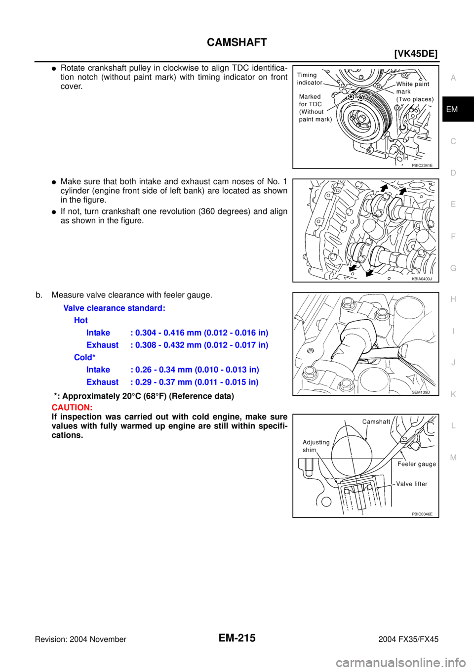
�Rotate crankshaft pulley in clockwise to align TDC identifica-
tion notch (without paint mark) with timing indicator on front
cover.
�Make sure that both intake and exhaust cam noses of No. 1
cylinder (engine front side of left bank) are located as shown
in the figure.
�If not, turn crankshaft one revolution (360 degrees) and align
as shown in the figure.
b. Measure valve clearance with feeler gauge.
*: Approximately 20°C (68°F) (Reference data)
CAUTION:
If inspection was carried out with cold engine, make sure
values with fully warmed up engine are still within specifi-
cations.
PBIC2341E
KBIA0400J
Valve clearance standard:
Hot
Intake : 0.304 - 0.416 mm (0.012 - 0.016 in)
Exhaust : 0.308 - 0.432 mm (0.012 - 0.017 in)
Cold*
Intake : 0.26 - 0.34 mm (0.010 - 0.013 in)
Exhaust : 0.29 - 0.37 mm (0.011 - 0.015 in)
SEM139D
PBIC0046E
Page 2941 of 4449
![INFINITI FX35 2004 Service Manual EM-216
[VK45DE]
CAMSHAFT
Revision: 2004 November 2004 FX35/FX45
�By referring to the figure, measure valve clearances at loca-
tions marked “×” as shown in the table below (locations indi-
cated](/manual-img/42/57021/w960_57021-2940.png "INFINITI FX35 2004 Service Manual EM-216
[VK45DE]
CAMSHAFT
Revision: 2004 November 2004 FX35/FX45
�By referring to the figure, measure valve clearances at loca-
tions marked “×” as shown in the table below (locations indi-
cated")
EM-216
[VK45DE]
CAMSHAFT
Revision: 2004 November 2004 FX35/FX45
�By referring to the figure, measure valve clearances at loca-
tions marked “×” as shown in the table below (locations indi-
cated with black arrow in figure).
NOTE:
Firing order 1-8-7-3-6-5-4-2
�No.1 cylinder compression TDC
c. Rotate crankshaft pulley clockwise (when view from engine
front) by 270 degrees from the position of No. 1 cylinder com-
pression TDC to align No. 3 cylinder at TDC of its compression
stroke.
NOTE:
Crankshaft pulley mounting bolt flange has a angle mark every
90 degrees. They can be used as a guide to rotation angle.
�By referring to the figure, measure valve clearances at loca-
tions marked “×” as shown in the table below (locations indi-
cated with white arrow in figure)
�No.3 cylinder compression TDC
Measuring position (right bank)No. 2
CYL.No. 4
CYL.No. 6
CYL.No. 8
CYL.
No. 1 cylinder at TDC EXH ×
INT××
Measuring position (left bank)No. 1
CYL.No. 3
CYL.No. 5
CYL.No. 7
CYL.
No. 1 cylinder at TDCINT××
EXH××
PBIC2358E
PBIC2346E
Measuring position (right bank)No. 2
CYL.No. 4
CYL.No. 6
CYL.No. 8
CYL.
No. 3 cylinder at TDC EXH ×
INT ×
Measuring position (left bank)No. 1
CYL.No. 3
CYL.No. 5
CYL.No. 7
CYL.
No. 3 cylinder at TDCINT××
EXH××
PBIC2358E