Page 3815 of 4449

MA-28
CHASSIS AND BODY MAINTENANCE
Revision: 2004 November 2004 FX35/FX45
CHASSIS AND BODY MAINTENANCEPFP:00100
Checking Exhaust SystemALS000FG
Check exhaust pipes, muffler and mounting for improper attachment,
leaks, cracks, damage, chafing or deterioration.
Checking A/T FluidALS000GB
1. Warm up engine.
2. Check for fluid leakage.
3. Remove the tightening bolt for ATF level gauge.
4. Before driving, fluid level can be checked at fluid temperatures of 30 to 50°C (86 to 122°F) using “COLD”
range on ATF level gauge as follows.
a. Park vehicle on level surface and set parking brake.
b. Start engine and move selector lever through each gear position. Leave selector lever in “P” position.
c. Check fluid level with engine idling.
d. Remove ATF level gauge and wipe clean with lint-free paper.
CAUTION:
When wiping away the fluid level gauge, always use lint-free paper, not a cloth one.
e. Re-insert ATF level gauge into charging pipe as far as it will go.
CAUTION:
To check fluid level, insert the ATF level gauge until the cap contacts the end of the charging pipe,
with the gauge reversed from the normal attachment conditions.
f. Remove ATF level gauge and note reading. If reading is at low side of range, add fluid to the charging
pipe.
CAUTION:
Do not overfill.
5. Drive vehicle for approximately 5 minutes in urban areas.
6. Make the fluid temperature approximately 65°C (149°F).
SMA211A
Page 3821 of 4449

MA-34
CHASSIS AND BODY MAINTENANCE
Revision: 2004 November 2004 FX35/FX45
Tire RotationALS000HB
�After rotation the tires, adjust the tire pressure.
�Retighten the wheel nuts when the vehicle has been driven for
1,000 km (600 miles) (also in cases of a flat tire, etc.).
CAUTION:
�Do not include the T-type spare tire when rotating the tires.
�When installing wheels, tighten them diagonally by dividing
the work two to three times in order to prevent the wheels
from developing any distortion.
Checking Brake Fluid Level and LeaksALS000FQ
�If fluid level is extremely low, check brake system for leaks.
Checking Brake Lines and CablesALS000FR
�Check brake fluid lines and parking brake cables for improper
attachment, leaks, chafing, abrasions, deterioration, etc.
Changing Brake FluidALS000FS
1. Drain brake fluid from each bleed valve.
2. Refill until new brake fluid comes out from each bleed valve.
Use same procedure as in bleeding hydraulic system to refill
brake fluid.
Refer to BR-10, "
Bleeding Brake System" .
�Refill with recommended Genuine Nissan Super Heavy Duty
Brake Fluid or equivalent DOT 3 (US FMVSS No. 116).
Refer to MA-12, "
RECOMMENDED FLUIDS AND LUBRI-
CANTS" .
�Never reuse drained brake fluid.
�Be careful not to splash brake fluid on painted areas.Tightening torque of wheel nut
: 108 N·m (11 kg, 80 ft-lb)
SMA829C
SBR451D
SBR389C
SBR419C
Page 3822 of 4449
CHASSIS AND BODY MAINTENANCE
MA-35
C
D
E
F
G
H
I
J
K
MA
B
MA
Revision: 2004 November 2004 FX35/FX45
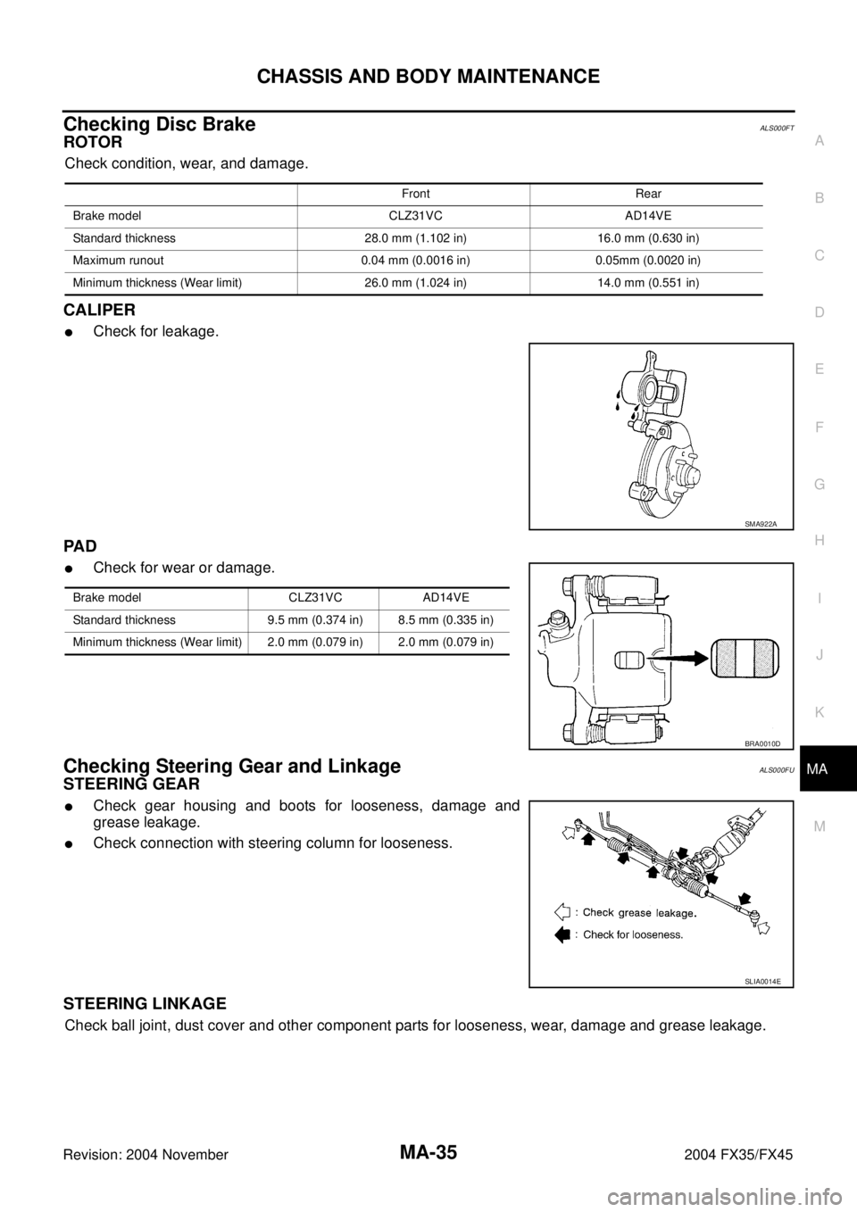
Checking Disc BrakeALS000FT
ROTOR
Check condition, wear, and damage.
CALIPER
�Check for leakage.
PA D
�Check for wear or damage.
Checking Steering Gear and LinkageALS000FU
STEERING GEAR
�Check gear housing and boots for looseness, damage and
grease leakage.
�Check connection with steering column for looseness.
STEERING LINKAGE
Check ball joint, dust cover and other component parts for looseness, wear, damage and grease leakage.
Front Rear
Brake model CLZ31VC AD14VE
Standard thickness 28.0 mm (1.102 in) 16.0 mm (0.630 in)
Maximum runout 0.04 mm (0.0016 in) 0.05mm (0.0020 in)
Minimum thickness (Wear limit) 26.0 mm (1.024 in) 14.0 mm (0.551 in)
SMA922A
Brake model CLZ31VC AD14VE
Standard thickness 9.5 mm (0.374 in) 8.5 mm (0.335 in)
Minimum thickness (Wear limit) 2.0 mm (0.079 in) 2.0 mm (0.079 in)
BRA0010D
SLIA0014E
Page 3828 of 4449

PB-1
PARKING BRAKE SYSTEM
F BRAKES
CONTENTS
C
D
E
G
H
I
J
K
L
M
SECTION PB
A
B
PB
Revision: 2004 November 2004 FX35/FX45
PARKING BRAKE SYSTEM
PARKING BRAKE SYSTEM ...................................... 2
On-Vehicle Service ................................................... 2
PEDAL STROKE ................................................... 2
INSPECT COMPONENTS .................................... 2
ADJUSTMENT ...................................................... 2
PARKING BRAKE CONTROL ................................... 3
Components ............................................................. 3
Removal and Installation .......................................... 3
REMOVAL ............................................................. 3
INSTALLATION ..................................................... 4PARKING BRAKE SHOE ........................................... 5
Components ............................................................. 5
Removal and Installation .......................................... 5
REMOVAL ............................................................. 5
INSPECTION AFTER REMOVAL ......................... 6
INSTALLATION ..................................................... 6
SERVICE DATA AND SPECIFICATIONS (SDS) ........ 7
Parking Drum Brake ................................................. 7
Parking Brake Control .............................................. 7
Page 3829 of 4449

PB-2
PARKING BRAKE SYSTEM
Revision: 2004 November 2004 FX35/FX45
PARKING BRAKE SYSTEMPFP:36010
On-Vehicle ServiceAFS001TJ
PEDAL STROKE
�When parking brake pedal is operated with a force of 200 N (20.4 kg, 44.9 lb), make sure the stroke is
within the specified number of notches. (Check it by listening and counting the ratchet clicks.)
INSPECT COMPONENTS
�Make sure the components are attached properly (check for looseness, backlash, etc.).
�Check parking brake pedal assembly for bend, damage and cracks, and replace if necessary.
�Check cable for wear and damage, and replace if necessary.
�Check parking brake warning lamp switch for malfunction, and replace if necessary.
ADJUSTMENT
�To perform adjustment operations, remove tire from the vehicle with power tool.
1. Insert a deep socket wrench to rotate adjusting nut and loosen
cable sufficiently. Then, return pedal.
2. Using wheel nuts, fix disc to hub and prevent it from tilting.
3. Remove adjusting hole plug installed on disc. Using a flat-
bladed screwdriver, turn Adjuster in direction A as shown in the
figure until disc rotor is locked. After locking, turn adjuster in the
opposite direction by 5 or 6 notches.
4. Rotate disc rotor to make sure there is no drag. Install adjusting
hole plug.
5. Adjust cable as follows:
a. Operate pedal 10 or more times with a force of 490 N (50 kg,
11 0 l b ) .
b. Rotate adjusting nut with deep socket to adjust pedal stroke.
CAUTION:
Do not reuse adjusting nut after removing it.
c. When parking brake pedal is operated with a force of 200 N (20.4 kg, 44.9 lb), make sure the stroke is
within the specified number of notches. (Check it by listening and counting the ratchet clicks.)
d. With pedal completely returned, make sure there is no drag on rear brake.Pedal stroke : 4 − 5 notches
SFIA1139E
Pedal stroke : 4 − 5 notches
PFIA0295E
Page 3830 of 4449

PARKING BRAKE CONTROL
PB-3
C
D
E
G
H
I
J
K
L
MA
B
PB
Revision: 2004 November 2004 FX35/FX45
PARKING BRAKE CONTROLPFP:36010
ComponentsAFS001TK
Removal and InstallationAFS001TL
REMOVAL
1. Remove front kicking plate (driver side). Refer to IP-12, "(A) Front Kicking Plate (LH/RH)" .
2. Remove front body side welt (driver side). Refer to EI-37, "
BODY SIDE TRIM" .
3. Remove dash side finisher (driver side). Refer to IP-10, "
INSTRUMENT PANEL ASSEMBLY" .
4. Remove instrument lower panel (driver side). Refer to IP-10, "
INSTRUMENT PANEL ASSEMBLY" .
5. Remove adjusting nut.
6. Remove front cable installation bolts, nuts, and lock plate, then remove front cable from the vehicle.
7. Remove heat insulator between center tube and rear propeller shaft.
8. Remove exhaust center muffler. Refer to EX-3, "
EXHAUST SYSTEM" .
9. Remove propeller shaft. Refer to PR-7, "
Removal and Installation" .
10. Remove rear disc caliper and disc rotors. Refer to BR-26, "
Removal and Installation of Brake Caliper
Assembly" .
11. Remove parking brake shoe, and remove rear cable from toggle lever. Refer to PB-5, "
PARKING BRAKE
SHOE" .
1. Device assembly 2. Spring insulator 3. Return spring
4. Lock plate 5. Front cable 6. Return spring
7. Rear left cable 8. Rear right cable 9. Pin
10. Adjusting nut
SFIA1943E
Page 3831 of 4449
PB-4
PARKING BRAKE CONTROL
Revision: 2004 November 2004 FX35/FX45
12. Remove right and left rear cables installation nut, bolt, and remove right and left rear cable assembly from
the vehicle.
INSTALLATION
1. Refer to “Components” for tightening torque. Install in the reverse order of removal.
CAUTION:
Do not reuse adjusting nut after removing it.
2. Adjust parking brake. Refer to PB-2, "
ADJUSTMENT" .
Page 3832 of 4449
PARKING BRAKE SHOE
PB-5
C
D
E
G
H
I
J
K
L
MA
B
PB
Revision: 2004 November 2004 FX35/FX45
PARKING BRAKE SHOEPFP:44060
ComponentsAFS001TM
Removal and InstallationAFS001TN
REMOVAL
WARNING:
Clean brakes with a vacuum dust collector to minimize the hazard of airborne particles or other mate-
rials.
Be careful of the following:
�Remove disc rotor only with parking brake pedal completely in the returned position.
�If disc rotor cannot be removed, remove as follows.
1. Fix disc rotor in place with wheel nuts and remove disc rotor
plug. Using a flat-bladed screwdriver, rotate adjuster on adjuster
assembly in direction B to retract and loosen brake shoes.
1. Back plate 2. Anchor block 3. Toggle lever
4. shoe 5. Adjuster 6. Return spring
7. Anti-rattle spring 8. Retainer 9. Anti-rattle pin
SFIA1167E
PFIA0309E