Page 2815 of 4449
EM-90
[VQ35DE]
CAMSHAFT
Revision: 2004 November 2004 FX35/FX45
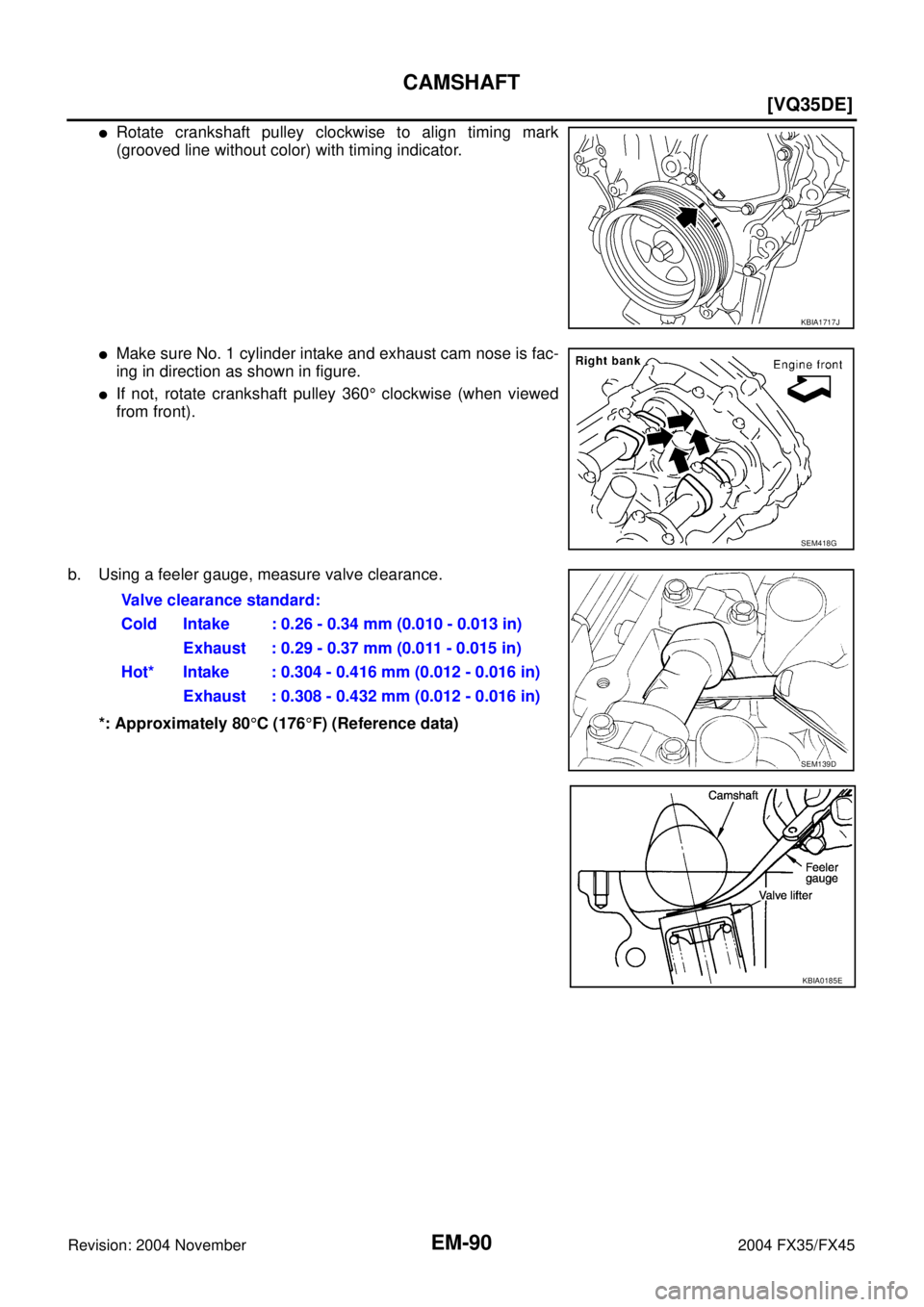
�Rotate crankshaft pulley clockwise to align timing mark
(grooved line without color) with timing indicator.
�Make sure No. 1 cylinder intake and exhaust cam nose is fac-
ing in direction as shown in figure.
�If not, rotate crankshaft pulley 360° clockwise (when viewed
from front).
b. Using a feeler gauge, measure valve clearance.
*: Approximately 80°C (176°F) (Reference data)
KBIA1717J
SEM418G
Valve clearance standard:
Cold Intake : 0.26 - 0.34 mm (0.010 - 0.013 in)
Exhaust : 0.29 - 0.37 mm (0.011 - 0.015 in)
Hot* Intake : 0.304 - 0.416 mm (0.012 - 0.016 in)
Exhaust : 0.308 - 0.432 mm (0.012 - 0.016 in)
SEM139D
KBIA0185E
Page 2816 of 4449
CAMSHAFT
EM-91
[VQ35DE]
C
D
E
F
G
H
I
J
K
L
MA
EM
Revision: 2004 November 2004 FX35/FX45
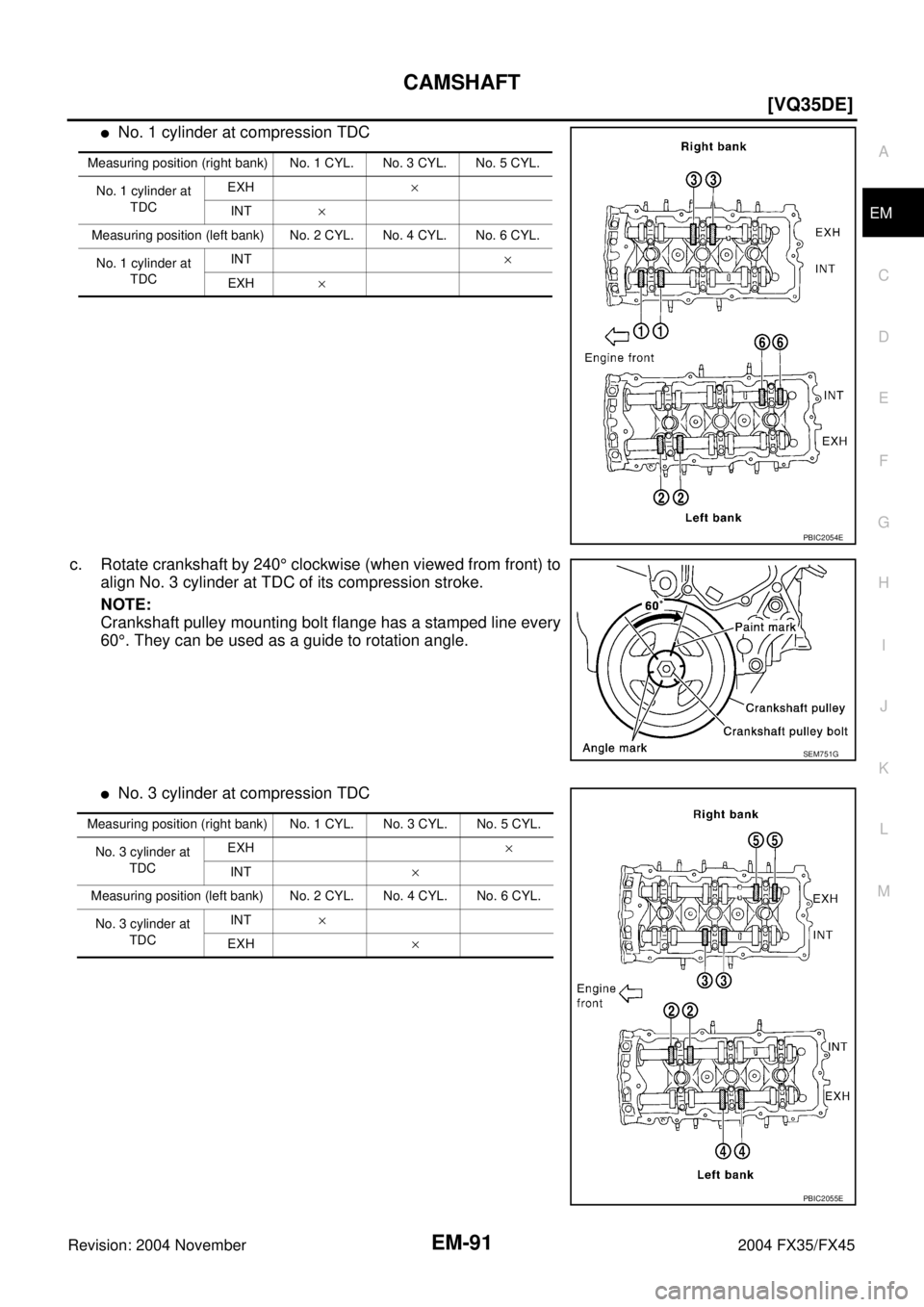
�No. 1 cylinder at compression TDC
c. Rotate crankshaft by 240° clockwise (when viewed from front) to
align No. 3 cylinder at TDC of its compression stroke.
NOTE:
Crankshaft pulley mounting bolt flange has a stamped line every
60°. They can be used as a guide to rotation angle.
�No. 3 cylinder at compression TDC
Measuring position (right bank) No. 1 CYL. No. 3 CYL. No. 5 CYL.
No. 1 cylinder at
TDCEXH×
INT×
Measuring position (left bank) No. 2 CYL. No. 4 CYL. No. 6 CYL.
No. 1 cylinder at
TDCINT×
EXH×
PBIC2054E
SEM751G
Measuring position (right bank) No. 1 CYL. No. 3 CYL. No. 5 CYL.
No. 3 cylinder at
TDCEXH×
INT×
Measuring position (left bank) No. 2 CYL. No. 4 CYL. No. 6 CYL.
No. 3 cylinder at
TDCINT×
EXH ×
PBIC2055E
Page 2817 of 4449
![INFINITI FX35 2004 Service Manual EM-92
[VQ35DE]
CAMSHAFT
Revision: 2004 November 2004 FX35/FX45
d. Rotate crankshaft by 240 degrees clockwise (when viewed from
engine front) to align No. 5 cylinder at TDC of compression
stroke.
�No](/manual-img/42/57021/w960_57021-2816.png "INFINITI FX35 2004 Service Manual EM-92
[VQ35DE]
CAMSHAFT
Revision: 2004 November 2004 FX35/FX45
d. Rotate crankshaft by 240 degrees clockwise (when viewed from
engine front) to align No. 5 cylinder at TDC of compression
stroke.
�No")
EM-92
[VQ35DE]
CAMSHAFT
Revision: 2004 November 2004 FX35/FX45
d. Rotate crankshaft by 240 degrees clockwise (when viewed from
engine front) to align No. 5 cylinder at TDC of compression
stroke.
�No. 5 cylinder at compression TDC
CAUTION:
If inspection was carried out with cold engine, make sure
values with fully warmed up engine are still within speci-
fications.
3. For measurements that are outside the specified range, perform adjustment below.
ADJUSTMENT
�Perform adjustment depending on selected head thickness of valve lifter.
�The specified valve lifter thickness is the dimension at normal temperatures. Ignore dimensional differ-
ences caused by temperature. Use the specifications for hot engine condition to adjust.
1. Remove camshaft. Refer to EM-83, "
REMOVAL" .
2. Remove valve lifters at the locations that are outside the standard.
3. Measure the center thickness of the removed valve lifters with a
micrometer.
4. Use the equation below to calculate valve lifter thickness for replacement.
SEM751G
Measuring position (right bank) No. 1 CYL. No. 3 CYL. No. 5 CYL.
No. 5 cylinder at
TDCEXH×
INT×
Measuring position (left bank) No. 2 CYL. No. 4 CYL. No. 6 CYL.
No. 5 cylinder at
TDCINT×
EXH ×
PBIC2056E
KBIA0057E
Page 2821 of 4449
![INFINITI FX35 2004 Service Manual EM-96
[VQ35DE]
OIL SEAL
Revision: 2004 November 2004 FX35/FX45
INSTALLATION
1. Apply engine oil on new front oil seal.
2. Using a suitable drift, press fit until the height of front oil seal is
level](/manual-img/42/57021/w960_57021-2820.png "INFINITI FX35 2004 Service Manual EM-96
[VQ35DE]
OIL SEAL
Revision: 2004 November 2004 FX35/FX45
INSTALLATION
1. Apply engine oil on new front oil seal.
2. Using a suitable drift, press fit until the height of front oil seal is
level")
EM-96
[VQ35DE]
OIL SEAL
Revision: 2004 November 2004 FX35/FX45
INSTALLATION
1. Apply engine oil on new front oil seal.
2. Using a suitable drift, press fit until the height of front oil seal is
level with the mounting surface.
�Suitable drift: outer diameter 59 mm (2.32 in), inner diameter
49 mm (1.93 in).
CAUTION:
Press fit straight and avoid causing burrs or tilting oil
seal.
3. Perform steps in the reverse order of removal for the following operations.
Removal and Installation of Rear Oil SealABS004X6
REMOVAL
1. Remove oil pan (upper). Refer to EM-30, "OIL PAN AND OIL STRAINER" .
2. Remove transmission assembly. Refer to AT- 2 6 6 , "
TRANSMISSION ASSEMBLY" .
3. Remove drive plate with power tool. Fix crankshaft with a ring gear stopper [SST: KV1011770 (J-44716)],
and remove mounting bolts.
�Loosen mounting bolts in diagonal order.
CAUTION:
�Do not disassemble drive plate.
�Never place drive plate with signal plate facing down.
�When handling signal plate, take care not to damage or
scratch it.
�Handle signal plate in a manner that prevents it from
becoming magnetized.
4. Use a seal cutter (SST) to cut away liquid gasket and remove
rear oil seal retainer.
CAUTION:
Be careful not to damage mounting surface.
NOTE:
Rear oil seal and retainer form a single part and are handled as
an assembly.
INSTALLATION
1. Remove old liquid gasket on mating surface of cylinder block and oil pan using scraper.
SEM715A
SEM760G
SEM830E
Page 2822 of 4449
OIL SEAL
EM-97
[VQ35DE]
C
D
E
F
G
H
I
J
K
L
MA
EM
Revision: 2004 November 2004 FX35/FX45
2. Apply new engine oil to the oil and dust seal lips.
3. Apply liquid gasket to rear oil seal retainer with tube presser
[SST: WS39930000 ( – )] as shown in the figure.
Use Genuine RTV Silicone Sealant or equivalent. Refer to
GI-48, "
RECOMMENDED CHEMICAL PRODUCTS AND
SEALANTS" .
�Assembly should be done within 5 minutes after coating.
4. Install rear oil seal retainer to cylinder block.
5. Perform steps in the reverse order of removal for the following operations.
PBIC0922E
Page 2825 of 4449
![INFINITI FX35 2004 Service Manual EM-100
[VQ35DE]
CYLINDER HEAD
Revision: 2004 November 2004 FX35/FX45
NOTE:
At the time of the start of this procedure front suspension member is removed, and cylinder head is
hanged by hoist with engi](/manual-img/42/57021/w960_57021-2824.png "INFINITI FX35 2004 Service Manual EM-100
[VQ35DE]
CYLINDER HEAD
Revision: 2004 November 2004 FX35/FX45
NOTE:
At the time of the start of this procedure front suspension member is removed, and cylinder head is
hanged by hoist with engi")
EM-100
[VQ35DE]
CYLINDER HEAD
Revision: 2004 November 2004 FX35/FX45
NOTE:
At the time of the start of this procedure front suspension member is removed, and cylinder head is
hanged by hoist with engine slinger installed.
3. Release hoist from hanging, then remove engine slinger.
4. Remove the following components and related parts:
�Fuel tube and fuel injector assembly. Refer to EM-45, "FUEL INJECTOR AND FUEL TUBE" .
�Intake manifold. Refer to EM-24, "INTAKE MANIFOLD" .
�Exhaust manifold. Refer to EM-26, "EXHAUST MANIFOLD AND THREE WAY CATALYST" .
�Water inlet and thermostat assembly. Refer to CO-26, "WATER INLET AND THERMOSTAT ASSEM-
BLY" .
�Water outlet and water piping. Refer to CO-28, "WATER OUTLET AND WATER PIPING" .
5. Remove cylinder head loosening bolts with power tool in reverse
order shown in the figure and using cylinder head bolt wrench
(commercial service tool).
6. Remove cylinder head gaskets.
INSPECTION AFTER REMOVAL
Outer Diameter of Cylinder Head Bolts
�Cylinder head bolts are tightened by plastic zone tightening
method. Whenever the size difference between d1 and d2
exceeds the limit, replace them with new one.
�If reduction of outer diameter appears in a position other than
d2, use it as d2 point.
Cylinder Head Distortion
NOTE:
When performing this inspection, cylinder block distortion should be also checking. Refer to EM-139, "
CYLIN-
DER BLOCK DISTORTION" .
1. Using scraper, wipe off oil, scale, gasket, sealant and carbon deposits from surface of cylinder head.
CAUTION:
Do not allow gasket fragments to enter engine oil or engine coolant passages.
PBIC2057E
Limit (d1 - d2) : 0.11 mm (0.0043 in)
SEM957E
Page 2827 of 4449
![INFINITI FX35 2004 Service Manual EM-102
[VQ35DE]
CYLINDER HEAD
Revision: 2004 November 2004 FX35/FX45
d. Turn all bolts “90” degrees clockwise (angle tightening).
e. Turn all bolts “90” degrees clockwise again [target: 90 deg](/manual-img/42/57021/w960_57021-2826.png "INFINITI FX35 2004 Service Manual EM-102
[VQ35DE]
CYLINDER HEAD
Revision: 2004 November 2004 FX35/FX45
d. Turn all bolts “90” degrees clockwise (angle tightening).
e. Turn all bolts “90” degrees clockwise again [target: 90 deg")
EM-102
[VQ35DE]
CYLINDER HEAD
Revision: 2004 November 2004 FX35/FX45
d. Turn all bolts “90” degrees clockwise (angle tightening).
e. Turn all bolts “90” degrees clockwise again [target: 90 degrees
(angle tightening)].
CAUTION:
Check and confirm the tightening angle by using angle
wrench (SST) and cylinder head bolt wrench (commercial
service tool). Avoid judgment by visual inspection without
SST.
�Check tightening angle indicated on angle wrench (SST) indi-
cator plate.
4. After installing cylinder head, measure distance between front
end faces of cylinder block and cylinder head (left and right
banks).
�If measurement is outside the specified range, re-install cylin-
der head.
5. Perform steps in reverse order of removal for the following operations.
Disassembly and AssemblyABS004X9
PBIC0888E
Standard : 14.1 - 14.9 mm (0.555 - 0.587 in)
EMQ0662D
1. Valve lifter 2. Valve collet 3. Valve spring retainer
4. Valve spring 5. Valve oil seal 6. Valve spring seat
7. Valve guide 8. Spark plug 9. Spark plug tube
PBIC2308E
Page 2838 of 4449
![INFINITI FX35 2004 Service Manual ENGINE ASSEMBLY
EM-113
[VQ35DE]
C
D
E
F
G
H
I
J
K
L
MA
EM
Revision: 2004 November 2004 FX35/FX45
Separation Work
1. Install engine slingers into front of right bank cylinder head and
rear of left bank](/manual-img/42/57021/w960_57021-2837.png "INFINITI FX35 2004 Service Manual ENGINE ASSEMBLY
EM-113
[VQ35DE]
C
D
E
F
G
H
I
J
K
L
MA
EM
Revision: 2004 November 2004 FX35/FX45
Separation Work
1. Install engine slingers into front of right bank cylinder head and
rear of left bank")
ENGINE ASSEMBLY
EM-113
[VQ35DE]
C
D
E
F
G
H
I
J
K
L
MA
EM
Revision: 2004 November 2004 FX35/FX45
Separation Work
1. Install engine slingers into front of right bank cylinder head and
rear of left bank cylinder head.
2. Remove power steering oil pump from engine side. Refer to PS-
31, "POWER STEERING OIL PUMP" .
3. Remove engine mounting insulator under side nut with power
tool.
4. Lift with hoist and separate engine and transmission assembly
from suspension member.
CAUTION:
�Before and during this lifting, always check if any harnesses are left connected.
�Avoid damage to and oil/grease smearing or spills onto engine mounting insulator.
5. Remove alternator. Refer to SC-23, "
CHARGING SYSTEM" .
6. Remove starter motor. Refer to SC-10, "
STARTING SYSTEM" .
7. Separate engine from transmission assembly. Refer to AT- 2 6 6 , "
TRANSMISSION ASSEMBLY" .
8. Remove engine mounting insulator and bracket with power tool.
INSTALLATION
Note to the following, and install in the reverse order of removal.
�For a location with a positioning pin, insert it securely into hole of
mating part.
�For a part with a specified installation orientation, refer to com-
ponent figure in EM-110, "
2WD MODEL" .
�When installing engine mounting bracket on cylinder block,
tighten two upper bolts (shown as A in figure) first. Then tighten
two lower bolts (shown as B in figure). (LH and RH sides)
�Tighten rear member mounting bolts in numerical order shown
in figure.
INSPECTION AFTER INSTALLATION
�Before starting engine, check the levels of engine coolant, engine oil and working fluid. If less than
required quantity, fill to the specified level.
�Use procedure below to check for fuel leakage.
–Turn ignition switch ON (with engine stopped). With fuel pressure applied to fuel piping, check for fuel
leakage at connection points.
–Start engine. With engine speed increased, check again for fuel leakage at connection points.
�Run engine to check for unusual noise and vibration.
�Warm up engine thoroughly to make sure there is no leakage of engine coolant, engine oil, working fluid,
fuel and exhaust gas.Slinger bolts:
: 28.0 N·m (2.9 kg-m, 21 ft-lb)
SBIA0474E
PBIC1134E
KBIA1019E
![INFINITI FX35 2004 Service Manual OIL SEAL
EM-97
[VQ35DE]
C
D
E
F
G
H
I
J
K
L
MA
EM
Revision: 2004 November 2004 FX35/FX45
2. Apply new engine oil to the oil and dust seal lips.
3. Apply liquid gasket to rear oil seal retainer with tu](/manual-img/42/57021/w960_57021-2821.png "INFINITI FX35 2004 Service Manual OIL SEAL
EM-97
[VQ35DE]
C
D
E
F
G
H
I
J
K
L
MA
EM
Revision: 2004 November 2004 FX35/FX45
2. Apply new engine oil to the oil and dust seal lips.
3. Apply liquid gasket to rear oil seal retainer with tu")