Page 3972 of 4449

POWER STEERING OIL PUMP
PS-39
C
D
E
F
H
I
J
K
L
MA
B
PS
Revision: 2004 November 2004 FX35/FX45
1. Apply a coat of Genuine Nissan PSF or equivalent to oil seal lip
and to the circumference of oil seal. Using proper tool, such as
hand press machine, install it to body assembly.
NOTE:
Do not reuse oil seal.
2. Apply a coat of Genuine Nissan PSF or equivalent to drive shaft
assembly and press drive shaft assembly into body assembly
with suitable tool, then install snap ring.
NOTE:
Do not reuse snap ring.
3. Apply a coat of Genuine Nissan PSF or equivalent to O-ring and
Install O-ring into body assembly.
NOTE:
Do not reuse O-ring.
4. Install side plate to body assembly.
5. Install lock pin into lock pin hole, and install cam-ring as shown
in the figure.
�When installing cam-ring, turn carved face with a letter (E) of
it to rear cover.
CAUTION:
Do not confuse the assembling direction of cam ring. If
cam ring is installed facing the incorrect direction, it may
cause pump operation malfunction.
6. Install rotor to body assembly.
SST038A
SGIA0422E
SGIA0591E
Page 3973 of 4449
PS-40
POWER STEERING OIL PUMP
Revision: 2004 November 2004 FX35/FX45
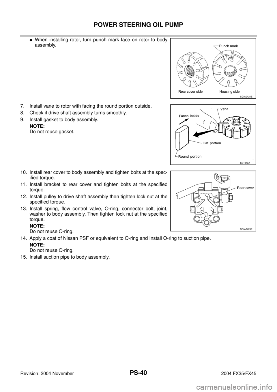
�When installing rotor, turn punch mark face on rotor to body
assembly.
7. Install vane to rotor with facing the round portion outside.
8. Check if drive shaft assembly turns smoothly.
9. Install gasket to body assembly.
NOTE:
Do not reuse gasket.
10. Install rear cover to body assembly and tighten bolts at the spec-
ified torque.
11. Install bracket to rear cover and tighten bolts at the specified
torque.
12. Install pulley to drive shaft assembly then tighten lock nut at the
specified torque.
13. Install spring, flow control valve, O-ring, connector bolt, joint,
washer to body assembly. Then tighten lock nut at the specified
torque.
NOTE:
Do not reuse O-ring.
14. Apply a coat of Nissan PSF or equivalent to O-ring and Install O-ring to suction pipe.
NOTE:
Do not reuse O-ring.
15. Install suction pipe to body assembly.
SGIA0424E
SST843A
SGIA0425E
Page 3974 of 4449
HYDRAULIC LINE
PS-41
C
D
E
F
H
I
J
K
L
MA
B
PS
Revision: 2004 November 2004 FX35/FX45
HYDRAULIC LINEPFP:49721
ComponentsAGS000H5
VQ35DE 2WD MODEL
SGIA0559E
1. Reservoir tank 2. Reservoir tank bracket 3. Suction hose
4. High pressure hose 5. Oil pump 6. Steering gear assembly
Page 3975 of 4449
PS-42
HYDRAULIC LINE
Revision: 2004 November 2004 FX35/FX45
VQ35DE AWD MODEL
7. Oil cooler 8. Eye bolt 9. Copper washer
10. Oil pressure sensor
SGIA0560E
1. Reservoir tank 2. Reservoir tank bracket 3. Suction hose
4. High pressure hose 5. Oil pump 6. Steering gear assembly
7. Oil cooler 8. Eye bolt 9. Copper washer
10. Oil pressure sensor
Page 3976 of 4449
HYDRAULIC LINE
PS-43
C
D
E
F
H
I
J
K
L
MA
B
PS
Revision: 2004 November 2004 FX35/FX45
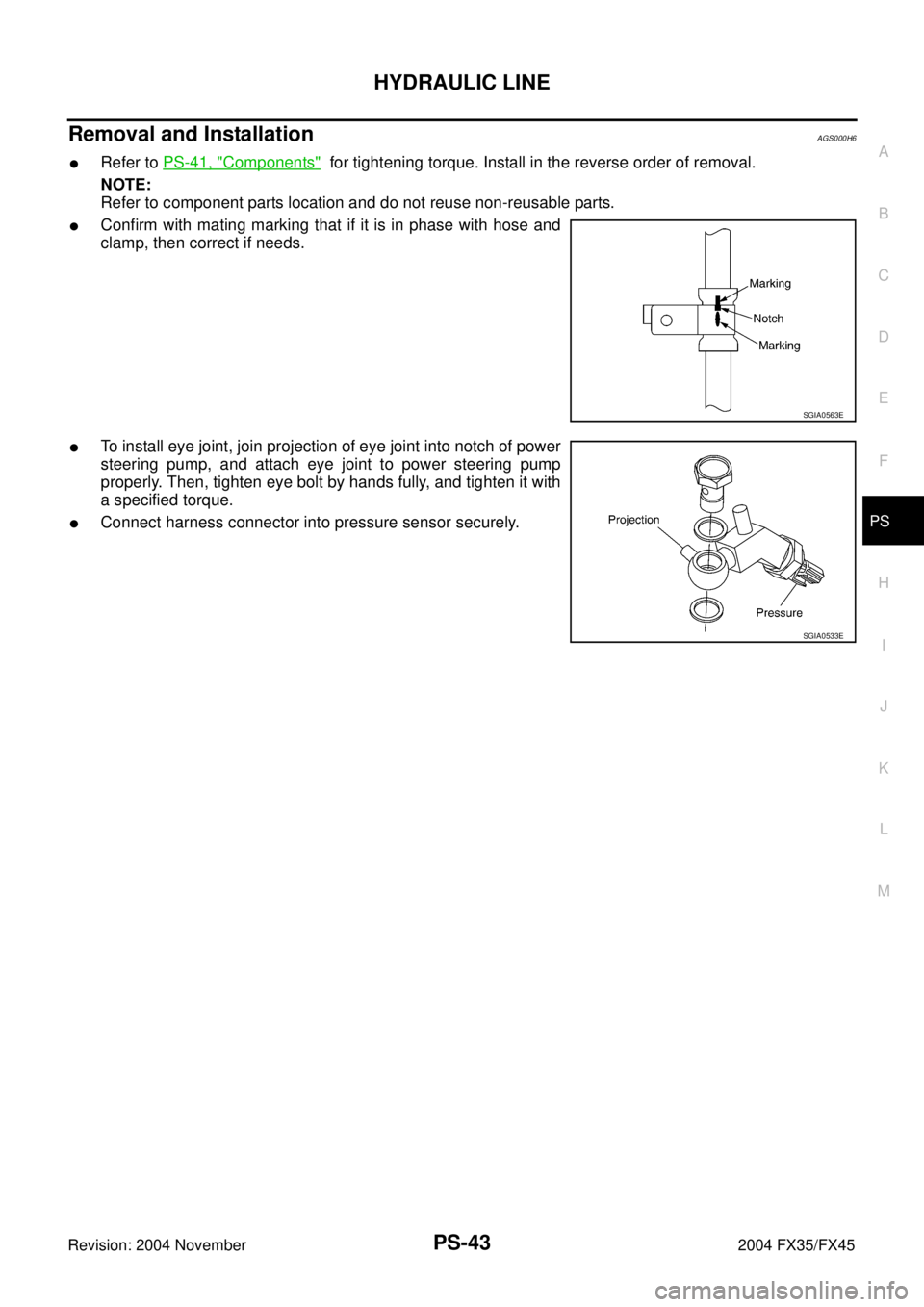
Removal and InstallationAGS000H6
�Refer to PS-41, "Components" for tightening torque. Install in the reverse order of removal.
NOTE:
Refer to component parts location and do not reuse non-reusable parts.
�Confirm with mating marking that if it is in phase with hose and
clamp, then correct if needs.
�To install eye joint, join projection of eye joint into notch of power
steering pump, and attach eye joint to power steering pump
properly. Then, tighten eye bolt by hands fully, and tighten it with
a specified torque.
�Connect harness connector into pressure sensor securely.
SGIA0563E
SGIA0533E
Page 3977 of 4449
PS-44
HYDRAULIC LINE
Revision: 2004 November 2004 FX35/FX45
ComponentAGS000HF
VK45DE AWD MODEL
SGIA0727E
1. Reservoir tank 2. Suction hose 3. High pressure hose
4. Oil cooler 5. Steering gear assembly 6. Reservoir tank bracket
7. Eye bolt
Page 3978 of 4449
HYDRAULIC LINE
PS-45
C
D
E
F
H
I
J
K
L
MA
B
PS
Revision: 2004 November 2004 FX35/FX45
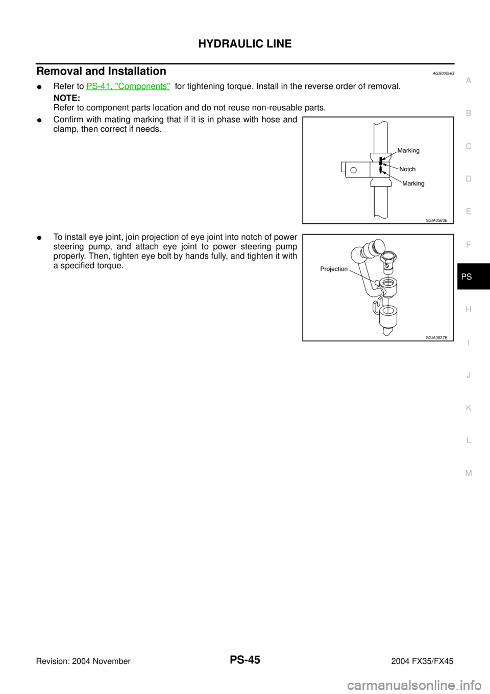
Removal and InstallationAGS000HG
�Refer to PS-41, "Components" for tightening torque. Install in the reverse order of removal.
NOTE:
Refer to component parts location and do not reuse non-reusable parts.
�Confirm with mating marking that if it is in phase with hose and
clamp, then correct if needs.
�To install eye joint, join projection of eye joint into notch of power
steering pump, and attach eye joint to power steering pump
properly. Then, tighten eye bolt by hands fully, and tighten it with
a specified torque.
SGIA0563E
SGIA0537E
Page 3979 of 4449

Revision: 2004 November 2004 FX35/FX45
SERVICE DATA AND SPECIFICATIONS (SDS)PFP:00030
Steering WheelAGS000H7
Steering AngleAGS000H8
Steering ColumnAGS000H9")
PS-46
SERVICE DATA AND SPECIFICATIONS (SDS)
Revision: 2004 November 2004 FX35/FX45
SERVICE DATA AND SPECIFICATIONS (SDS)PFP:00030
Steering WheelAGS000H7
Steering AngleAGS000H8
Steering ColumnAGS000H9
Steering Outer Socket and Inner SocketAGS000HA
End play of the axle direction for steering wheel 0 mm (0 in)
Steering wheel play on the outer circumference 0 − 35 mm (0 − 1.38 in)
Inner wheel
Degree minute (Decimal degree)Minimum 32°00′ (32.0°)
Nominal 35°00′ (35.0°)
Maximum 36°00′ (36.0°)
Outer wheel
Degree minute (Decimal degree)Nominal 30°00′ (30.0°)
Steering column length “ L1 ” 572 mm (22.52 in)
SGIA0556E
Steering gear typePR26AM
Tie-rod ball joint outer socketSwinging torque 0.3 − 2.9 N·m (0.03 − 0.29 kg-m, 3 − 25 in-lb)
Measurement on spring balance
�Measuring point: cotter pin hole of stud4.84 − 46.7 N (0.50 − 4.7 kg, 4 − 34 lb)
Rotating torque 0.3 − 2.9 N·m (0.03 − 0.29 kg-m, 3 − 25 in-lb)
Axial end play 0.5 mm (0.020 in) or less
Tie-rod ball joint inner socketSwinging torque 1.0 − 7.8 N·m (0.11 − 0.79 kg-m, 9 − 69 in-lb)
Measurement on spring balance
�Measuring point: L mark see below,
L=83.2 mm (3.276 in).12.1 − 93.7 N (1.3 − 9.5 kg, 9 − 69 lb)
Axial end play 0.2 mm (0.08 in) or less
SGIA0358E