Page 3027 of 4449
![INFINITI FX35 2004 Service Manual FAX-18
[AWD]
FRONT DRIVE SHAFT
Revision: 2004 November 2004 FX35/FX45
Wheel Side
1. Insert the amount grease (Nissan genuine grease or equivalent)
into joint sub-assembly serration hole until grease b](/manual-img/42/57021/w960_57021-3026.png "INFINITI FX35 2004 Service Manual FAX-18
[AWD]
FRONT DRIVE SHAFT
Revision: 2004 November 2004 FX35/FX45
Wheel Side
1. Insert the amount grease (Nissan genuine grease or equivalent)
into joint sub-assembly serration hole until grease b")
FAX-18
[AWD]
FRONT DRIVE SHAFT
Revision: 2004 November 2004 FX35/FX45
Wheel Side
1. Insert the amount grease (Nissan genuine grease or equivalent)
into joint sub-assembly serration hole until grease begins to
ooze from ball groove and serration hole. After inserting grease,
use a shop cloth to wipe off old grease that has oozed out.
2. Wind serrated part of shaft with tape. Install boot band and boot
to shaft. Be careful not to damage boot.
NOTE:
Discard old boot band and boot; replace with new ones.
3. Remove protective tape wound around serrated part of shaft.
4. Attach circular clip to shaft. At this time, circular clip must fit
securely into shaft groove. Attach nut to joint sub-assembly.
Use a wooden hammer to press-fit.
NOTE:
Discard old circular clip; replace with new one.
5. Insert the specified amount of grease (Nissan genuine grease or
equivalent) listed below into boot from large end of boot.
6. Install boot securely into grooves (indicated by * marks) shown
in the figure.
CAUTION:
If there is grease on boot mounting surfaces (indicated by*
marks) of shaft and housing of joint sub assembly, boot
may come off. Remove all grease from surfaces.
7. Make sure boot installation length “L” is the length indicated
below. Insert a flat-bladed screwdriver or similar tool into smaller
side of boot. Bleed air from boot to prevent boot deformation.
CAUTION:
�Boot may brake if boot installation length is less than standard value.
�Be careful that screwdriver tip does not contact inside surface of boot.
SDIA1127E
SFA800
Grease amount : 95 − 11 5 g ( 3 . 3 5 − 4.06 oz)
RAC0049D
Boot installation length “L” : 136 mm (5.35 in)SDIA1736E
Page 3032 of 4449
![INFINITI FX35 2004 Service Manual FRONT DRIVE SHAFT
FAX-23
[AWD]
C
E
F
G
H
I
J
K
L
MA
B
FA X
Revision: 2004 November 2004 FX35/FX45
2. Wind serrated part of shaft with tape. Install boot band and boot
to shaft. Be careful not to damag](/manual-img/42/57021/w960_57021-3031.png "INFINITI FX35 2004 Service Manual FRONT DRIVE SHAFT
FAX-23
[AWD]
C
E
F
G
H
I
J
K
L
MA
B
FA X
Revision: 2004 November 2004 FX35/FX45
2. Wind serrated part of shaft with tape. Install boot band and boot
to shaft. Be careful not to damag")
FRONT DRIVE SHAFT
FAX-23
[AWD]
C
E
F
G
H
I
J
K
L
MA
B
FA X
Revision: 2004 November 2004 FX35/FX45
2. Wind serrated part of shaft with tape. Install boot band and boot
to shaft. Be careful not to damage boot.
NOTE:
Discard old boot band and boot; replace with new ones.
3. Remove protective tape wound around serrated part of shaft.
4. Attach circular clip to shaft. At this time, circular clip must fit
securely into shaft groove. Attach nut to joint sub-assembly.
Use a wooden hammer to press-fit.
NOTE:
Discard old circular clip; replace with new one.
5. Insert the specified amount of grease (Nissan genuine grease or
equivalent) listed below into boot from large end of boot.
6. Install boot securely into grooves (indicated by * marks) shown
in the figure.
CAUTION:
If there is grease on boot mounting surfaces (indicated by*
marks) of shaft and housing of joint sub-assembly, boot
may come off. Remove all grease from surfaces.
7. Make sure boot installation length “L” is the length indicated
below. Insert a flat-bladed screwdriver or similar tool into smaller
side of boot. Bleed air from boot to prevent boot deformation.
CAUTION:
�Boot may brake if boot installation length is less than standard value.
�Be careful that screwdriver tip does not contact inside surface of boot.
8. Install new larger and smaller boot bands securely with a suit-
able tool.
NOTE:
�Discard old boot band; replace with new ones.
SFA800
Grease amount : 95 − 11 5 g ( 3 . 3 5 − 4.06 oz)
RAC0049D
Boot installation length “L” : 136 mm (5.35 in) SDIA1736E
RAC1133D
Page 3041 of 4449
FFD-6
NOISE, VIBRATION AND HARSHNESS (NVH) TROUBLESHOOTING
Revision: 2004 November 2004 FX35/FX45
NOISE, VIBRATION AND HARSHNESS (NVH) TROUBLESHOOTINGPFP:00003
NVH Troubleshooting ChartADS000N6
Use the chart below to help you find the cause of the symptom. If necessary, repair or replace these parts.
×: ApplicableReference page
Refer to FFD-24, "
INSPECTION
" .
Refer to FFD-30, "
TOOTH CONTACT INSPECTION
" .
Refer to FFD-24, "
INSPECTION
" .
Refer to RFD-13, "
Pre-Inspection
"
—
Refer to MA-31, "
Checking Differential Gear Oil
" .
NVH in PR section.
NVH in FAX, RAX, FSU and RSU sections.
NVH in WT section.
NVH in WT section.
NVH in FAX section.
NVH in BR section.
NVH in PS section.
Possible cause and suspected parts
Rough gear tooth
Improper gear contact
Tooth surfaces worn
Incorrect backlash
Companion flange excessive runout
Improper gear oil
Propeller shaft
Axle and suspension
Tire s
Road wheel
Drive shaft
Brakes
Steering
Symptom Differential Noise×××××××××××××
Page 3083 of 4449

FL-10
FUEL TANK
Revision: 2004 November 2004 FX35/FX45
FUEL TANKPFP:17202
Removal and InstallationABS005Z1
REMOVAL
WARNING:
Be sure to read “General Precautions” when working on the fuel system. Refer to FL-3, "
General Pre-
cautions" .
�Drain fuel from fuel tank if necessary. Refer to FL-4, "REMOVAL" .
�Perform work on level place.
1. Perform steps 2 to 7 of “REMOVAL” in “ FUEL LEVEL SENSOR UNIT, FUEL FILTER AND FUEL PUMP
ASSEMBLY” on main and sub fuel level sensor units. Refer to FL-4, "
REMOVAL" .
2. Remove tunnel stay. Refer to RSU-5, "
REAR SUSPENSION ASSEMBLY" .
3. Remove exhaust front tube, center muffler and main muffler. Refer to EX-3, "
EXHAUST SYSTEM" .
4. Remove insulator.
5. Remove propeller shaft. Refer to PR-6, "
REAR PROPELLER SHAFT" .
6. Remove parking rear brake cables. Refer to PB-3, "
PARKING BRAKE CONTROL" .
7. Remove rear suspension assembly. Refer to RSU-5, "
REAR SUSPENSION ASSEMBLY" .
8. Remove fuel tank protector.
1. Grommet 2. Fuel filler cap 3. Clip
4. Fuel filler tube protector 5. Fuel tank mounting band 6. Fuel tank protector
7. Insulator 8. Fuel tank 9. Vent tube
10. Vent hose 11. EVAP hose 12. Vent hose
13. Fuel filler hose 14. Fuel filler tube
PBIC1580E
Page 3089 of 4449
FSU-4
PREPARATION
Revision: 2004 November 2004 FX35/FX45
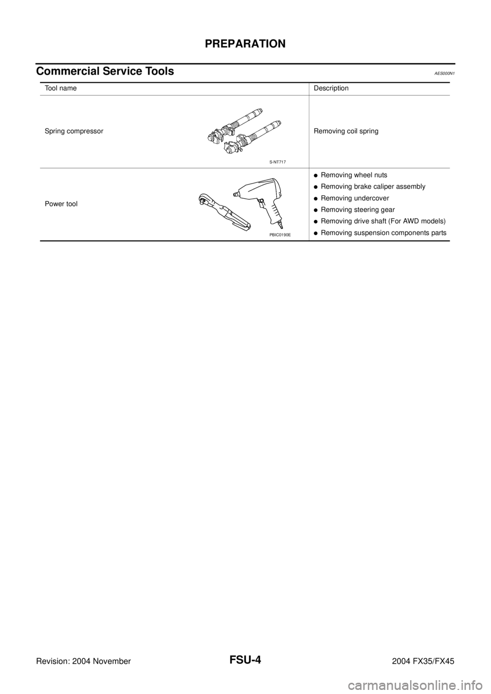
Commercial Service ToolsAES000N1
Tool nameDescription
Spring compressor Removing coil spring
Power tool
�Removing wheel nuts
�Removing brake caliper assembly
�Removing undercover
�Removing steering gear
�Removing drive shaft (For AWD models)
�Removing suspension components parts
S-NT717
PBIC0190E
Page 3090 of 4449
 TROUBLESHOOTING
FSU-5
C
D
F
G
H
I
J
K
L
MA
B
FSU
Revision: 2004 November 2004 FX35/FX45
NOISE, VIBRATION AND HARSHNESS (NVH) TROUBLESHOOTINGPFP:00003
NVH Troublesh")
NOISE, VIBRATION AND HARSHNESS (NVH) TROUBLESHOOTING
FSU-5
C
D
F
G
H
I
J
K
L
MA
B
FSU
Revision: 2004 November 2004 FX35/FX45
NOISE, VIBRATION AND HARSHNESS (NVH) TROUBLESHOOTINGPFP:00003
NVH Troubleshooting ChartAES000N2
Use chart below to help you find the cause of the symptom. If necessary, repair or replace these parts.
×: ApplicableReference page
FSU-8FSU-12
—
—
—
FSU-8FSU-6FSU-16
NVH in PR section
NVH in RFD section
NVH in RAX and RSU section
NVH in WT section
NVH in WT section
NVH in RAX section
NVH in BR section
NVH in PS section
Possible cause and SUSPECTED PARTS
Improper installation, looseness
Strut deformation, damage or deflection
Bushing or mounting deterioration
Parts interference
Spring fatigue
Suspension looseness
Incorrect wheel alignment
Stabilizer bar fatigue
PROPELLER SHAFT (For AWD models)
DIFFERENTIAL (For AWD models)
REAR AXLE AND REAR SUSPENSION
TIRES
ROAD WHEEL
DRIVE SHAFT (For AWD models)
BRAKES
STEERING
Symptom FRONT SUSPENSIONNoise××××× × ××× ×××××
Shake×××× × × × ×××××
Vibration××××× × ×× × ×
Shimmy×××× × ××× ××
Judder××× ××× ××
Poor quality ride or han-
dling××××× ×× ×××
Page 3091 of 4449

FSU-6
FRONT SUSPENSION ASSEMBLY
Revision: 2004 November 2004 FX35/FX45
FRONT SUSPENSION ASSEMBLYPFP:54010
On-Vehicle Inspection and ServiceAES000N3
Make sure the mounting conditions (looseness, back lash) of each component and component statues (wear,
damage) are normal.
INSPECTION OF TRANSVERSE LINK BALL JOINT END PLAY
1. Set front wheels in a straight-ahead position. Do not depress brake pedal.
2. Measure axial end play by installing and moving up/down between transverse link and steering knuckle
with an iron pry bar or something similar.
CAUTION:
Be careful not to damage ball joint boot.
STRUT INSPECTION
Check strut for oil leakage, damage and replace if necessary. Refer to FSU-11, "COIL SPRING AND STRUT" .
Wheel Alignment InspectionAES000N4
DESCRIPTION
Measure wheel alignment under unladen conditions.
NOTE:
Unladen conditions mean that fuel, engine coolant, and lubricant are full. Spare tire, jack, hand tools and mats
are designated positions.
PRELIMINARY CHECK
1. Check tires for improper air pressure and wear.
2. Check road wheels for runout.
3. Check wheel bearing axial end play.
4. Check transverse link ball joint axial end play.
5. Check strut operation.
6. Check each mounting part of axle and suspension for looseness and deformation.
7. Check each link, rod and member for cracks, deformation and other damage.
8. Check vehicle posture.
INSPECTION OF CAMBER, CASTER AND KINGPIN INCLINATION ANGLES
�Camber, caster, kingpin inclination angles cannot be adjusted.
�Before inspection, mount front wheels onto turning radius gauge. Mount rear wheels onto a stand that has
same height so vehicle will remain horizontal.
Using a CCK Gauge
Install CCK gauge attachment (SST: KV991040S0) as following procedure in wheel, then measure wheel
alignment.
1. Remove wheel nuts (3), and install a guide bolt to hub bolt.
2. Screw adapter into plate body until it contacts body tightly.
3. Screw center plate into plate.
4. Insert plate on guide bolt. Put spring in, and then evenly screw
both guide bolt nut. When fastening guide bolt nut, do not com-
pletely compress spring.Axial end play : 0 mm (0 in)
SEIA0240E
Page 3094 of 4449

FRONT SUSPENSION ASSEMBLY
FSU-9
C
D
F
G
H
I
J
K
L
MA
B
FSU
Revision: 2004 November 2004 FX35/FX45
Removal and InstallationAES000N6
REMOVAL
1. Set an engine slinger to engine, then suspend engine.
2. Remove tire from vehicle with power tool.
3. Remove brake caliper with power tool. Hang it in a place where it will not interfere with work. Refer to BR-
20, "FRONT DISC BRAKE" .
4. Remove brake hose lock plate. Then remove brake hose from
strut assembly.
5. Remove disc rotor.
6. Remove wheel sensor harness from strut assembly.
CAUTION:
Do not pull on wheel sensor harness.
7. Remove undercover with power tool.
8. Remove front cross bar.
9. Remove steering hydraulic piping bracket from front suspension
member. Refer to PS-41, "
HYDRAULIC LINE" .
10. Remove cotter pin at steering outer socket, then loosen mount-
ing nut.
11. Use a ball joint remover (SST) to remove steering outer socket
from steering knuckle. Be careful not to damage ball joint boot.
CAUTION:
Tighten temporarily mounting nut to prevent damage to
threads and to prevent ball joint remover (SST) from com-
ing off.
12. Remove mounting bolts of steering gear with power tool, then
hang steering gear on vehicle. Refer to PS-19, "
POWER
STEERING GEAR AND LINKAGE" .
13. Remove front final drive side of drive shaft with power tool. (For
AWD models) Refer to FAX-12, "
Removal and Installation (Left
Side)" , FA X - 1 3 , "Removal and Installation (Right Side)" .
14. Set jack under front suspension member.
15. Remove fixing bolts and nuts between strut assembly and steering knuckle with power tool.
1. Strut upper plate 2. Strut spacer 3. Mounting insulator
4. Mounting insulator bracket 5. Mounting bearing 6. Spring upper seat
7. Spring upper rubber seat 8. Coil spring 9. Spring lower rubber seat
10. Bound bumper 11. Strut 12. Steering knuckle
13. Front suspension member 14. Transverse link 15. Stabilizer bar
16. Stabilizer bushing 17. Stabilizer clamp 18. Stabilizer connecting rod
19. Front cross bar 20. Cotter pin
SEIA0328E
SEIA0329E
SDIA1434E
 TROUBLESHOOTING
Revision: 2004 November 2004 FX35/FX45
NOISE, VIBRATION AND HARSHNESS (NVH) TROUBLESHOOTINGPFP:00003
NVH Troubleshooting ChartADS000N6
Use th")