Page 1204 of 4449
![INFINITI FX35 2004 Service Manual RADIATOR
CO-15
[VQ35DE]
C
D
E
F
G
H
I
J
K
L
MA
CO
Revision: 2004 November 2004 FX35/FX45
8. Rotate two radiator upper mount brackets 90 degrees in the
direction shown in the figure, and remove them.
9](/manual-img/42/57021/w960_57021-1203.png "INFINITI FX35 2004 Service Manual RADIATOR
CO-15
[VQ35DE]
C
D
E
F
G
H
I
J
K
L
MA
CO
Revision: 2004 November 2004 FX35/FX45
8. Rotate two radiator upper mount brackets 90 degrees in the
direction shown in the figure, and remove them.
9")
RADIATOR
CO-15
[VQ35DE]
C
D
E
F
G
H
I
J
K
L
MA
CO
Revision: 2004 November 2004 FX35/FX45
8. Rotate two radiator upper mount brackets 90 degrees in the
direction shown in the figure, and remove them.
9. Lift up and remove radiator.
CAUTION:
Do not damage or scratch air conditioner condenser and
radiator core when removing.
INSTALLATION
Install in the reverse order of removal.
INSPECTION AFTER INSTALLATION
�Check for leaks of engine coolant using radiator cap tester adapter [SST: EG17650301 (J-33984-A)] and
radiator cap tester (commercial service tool). Refer to CO-11, "
CHECKING COOLING SYSTEM FOR
LEAKS" .
�Start and warm up engine. Visually make sure that there is no leaks of engine coolant and A/T fluid.
Checking Radiator CapABS008FW
1. Pull radiator cap negative-pressure valve to open it, and make
sure it close completely when released.
�Make sure there is no dirt or damage on valve seat of radiator
cap negative-pressure valve.
�Make sure there are no unusualness in the opening and clos-
ing conditions of radiator cap negative-pressure valve.
2. Check radiator cap relief pressure.
�When connecting radiator cap to radiator cap tester adapter
(SST) and radiator cap tester (commercial service tool), apply
engine coolant to the cap seal part.
�Replace radiator cap if there is an unusualness in radiator cap
negative-pressure valve, or if the open-valve pressure is out-
side of the standard values.
SBIA0447E
SBIA0448E
SMA967B
Standard
: 78 - 98 kPa (0.8 - 1.0 kg/cm
2 , 11 - 14 psi)
Limit
: 59 kPa (0.6 kg/cm
2 , 9 psi)
SLC755A
Page 1205 of 4449
CO-16
[VQ35DE]
RADIATOR
Revision: 2004 November 2004 FX35/FX45
Checking RadiatorABS008FX
Check radiator for mud or clogging. If necessary, clean radiator as follows.
�Be careful not to bend or damage radiator fins.
�When radiator is cleaned without removal, remove all surrounding parts such as cooling fan shroud and
horns. Then tape harness and connectors to prevent water from entering.
1. Apply water by hose to the back side of the radiator core vertically downward.
2. Apply water again to all radiator core surfaces once per minute.
3. Stop washing if any stains no longer flow out from radiator.
4. Blow air into the back side of radiator core vertically downward.
�Use compressed air lower than 490 kPa (5 kg/cm2 , 71 psi) and keep distance more than 30 cm (11.8
in).
5. Blow air again into all the radiator core surfaces once per minute until no water sprays out.
Page 1206 of 4449
RADIATOR (ALUMINUM TYPE)
CO-17
[VQ35DE]
C
D
E
F
G
H
I
J
K
L
MA
CO
Revision: 2004 November 2004 FX35/FX45
RADIATOR (ALUMINUM TYPE)PFP:21460
Disassembly and AssemblyABS004VZ
PREPARATION
1. Attach spacer to the tip of radiator plate pliers A (SST).
Spacer specification: 1.5 mm (0.059 in) thick x 18 mm (0.71 in)
wide x 8.5 mm (0.335 in) long.
2. Make sure that when radiator plate pliers A (SST) are closed
dimension H′′ is approx. 7.6 mm (0.299 in).
3. Adjust dimension H′′ with spacer, if necessary.
DISASSEMBLY
1. Remove upper or lower tanks with radiator plate pliers B (SST).
1. Upper tank 2. Sealing rubber 3. Core
4. Lower tank 5. Conical washer 6. Washer
7. O-ring 8. A/T fluid cooler
SBIA0449E
SLC655CB
SLC903-A
Page 1207 of 4449
CO-18
[VQ35DE]
RADIATOR (ALUMINUM TYPE)
Revision: 2004 November 2004 FX35/FX45
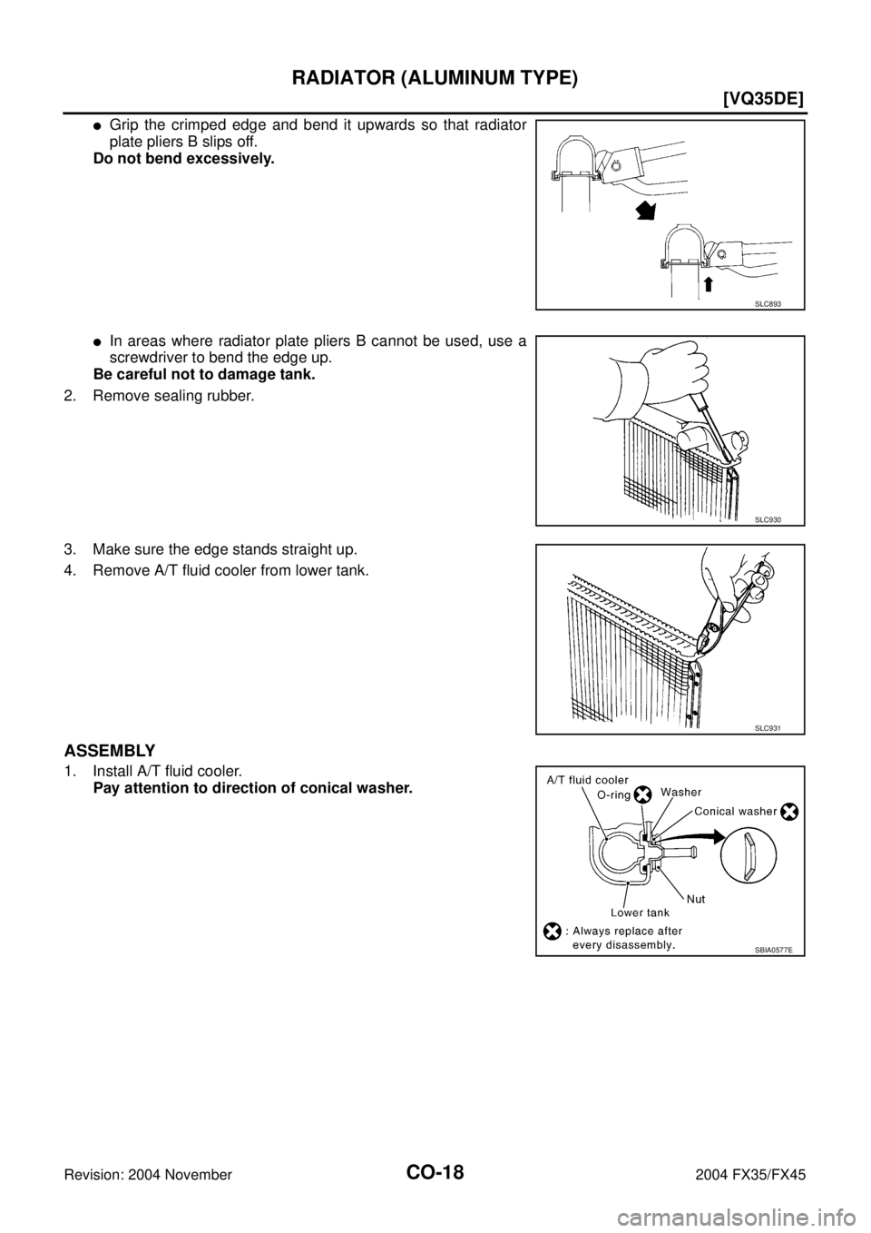
�Grip the crimped edge and bend it upwards so that radiator
plate pliers B slips off.
Do not bend excessively.
�In areas where radiator plate pliers B cannot be used, use a
screwdriver to bend the edge up.
Be careful not to damage tank.
2. Remove sealing rubber.
3. Make sure the edge stands straight up.
4. Remove A/T fluid cooler from lower tank.
ASSEMBLY
1. Install A/T fluid cooler.
Pay attention to direction of conical washer.
SLC893
SLC930
SLC931
SBIA0577E
Page 1208 of 4449
RADIATOR (ALUMINUM TYPE)
CO-19
[VQ35DE]
C
D
E
F
G
H
I
J
K
L
MA
CO
Revision: 2004 November 2004 FX35/FX45
2. Clean contact portion of tank.
3. Install sealing rubber.
Push it in with fingers.
Be careful not to twist sealing rubber.
4. Caulk tank in specified sequence with radiator plate pliers A
(SST).
SLC932
SLC917A
SLC904-A
SLC896
Page 1209 of 4449
CO-20
[VQ35DE]
RADIATOR (ALUMINUM TYPE)
Revision: 2004 November 2004 FX35/FX45
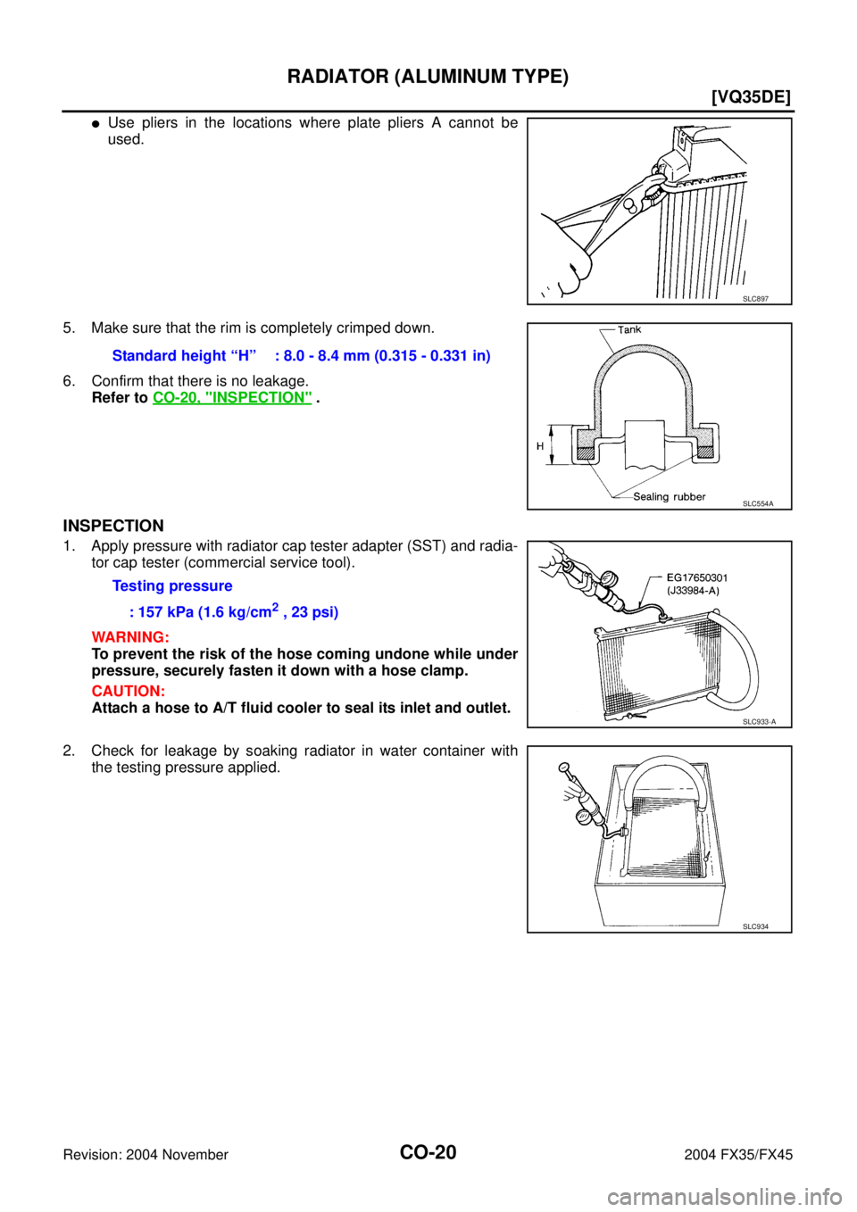
�Use pliers in the locations where plate pliers A cannot be
used.
5. Make sure that the rim is completely crimped down.
6. Confirm that there is no leakage.
Refer to CO-20, "
INSPECTION" .
INSPECTION
1. Apply pressure with radiator cap tester adapter (SST) and radia-
tor cap tester (commercial service tool).
WARNING:
To prevent the risk of the hose coming undone while under
pressure, securely fasten it down with a hose clamp.
CAUTION:
Attach a hose to A/T fluid cooler to seal its inlet and outlet.
2. Check for leakage by soaking radiator in water container with
the testing pressure applied.
SLC897
Standard height “H” : 8.0 - 8.4 mm (0.315 - 0.331 in)
SLC554A
Testing pressure
: 157 kPa (1.6 kg/cm
2 , 23 psi)
SLC933-A
SLC934
Page 1210 of 4449
COOLING FAN
CO-21
[VQ35DE]
C
D
E
F
G
H
I
J
K
L
MA
CO
Revision: 2004 November 2004 FX35/FX45
COOLING FANPFP:21140
Removal and Installation ABS005GR
REMOVAL
1. Remove air duct (inlet), power duct and air cleaner case assembly. Refer to EM-17, "AIR CLEANER AND
AIR DUCT" .
2. Disconnect fan motor connectors.
3. Remove radiator cooling fan assembly.
CAUTION:
Be careful not to damage or scratch on radiator core.
INSTALLATION
Note to the following, and install in the reverse order of removal.
�Cooling fan is controlled by ECM. For details, refer to EC-472, "DTC P1217 ENGINE OVER TEMPERA-
TURE" .
Disassembly and Assembly ABS004WG
DISASSEMBLY
1. Remove fans from fan motors.
2. Remove fan motors from fan shroud.
ASSEMBLY
Install in the reverse order of disassembly.
1. Cooling fan 2. Fan shroud 3. Fan motor
SBIA0594E
Page 1211 of 4449
![INFINITI FX35 2004 Service Manual CO-22
[VQ35DE]
WATER PUMP
Revision: 2004 November 2004 FX35/FX45
WATE R P U M PPFP:21020
Removal and InstallationABS009RE
CAUTION:
�When removing water pump, be careful not to get engine coolant on d](/manual-img/42/57021/w960_57021-1210.png "INFINITI FX35 2004 Service Manual CO-22
[VQ35DE]
WATER PUMP
Revision: 2004 November 2004 FX35/FX45
WATE R P U M PPFP:21020
Removal and InstallationABS009RE
CAUTION:
�When removing water pump, be careful not to get engine coolant on d")
CO-22
[VQ35DE]
WATER PUMP
Revision: 2004 November 2004 FX35/FX45
WATE R P U M PPFP:21020
Removal and InstallationABS009RE
CAUTION:
�When removing water pump, be careful not to get engine coolant on drive belt.
�Water pump cannot be disassembled and should be replaced as a unit.
REMOVAL
1. Remove front engine undercover with power tool.
2. Remove drive belts. Refer to EM-15, "
DRIVE BELTS" .
3. Drain engine coolant from radiator. Refer to CO-11, "
Changing Engine Coolant" .
CAUTION:
Perform when engine is cold.
4. Remove air duct (inlet), power duct and air cleaner case assembly. Refer to EM-17, "
AIR CLEANER AND
AIR DUCT" .
5. Remove water drain plug (front) of cylinder block.
6. Remove chain tensioner cover and water pump cover separat-
i n g t h e m a t i n g s u r f a c e w i t h a s e a l c u t t e r [ S S T: K V 1 0 1111 0 0 ( J -
37228)].
CAUTION:
Be careful not to damage the mating surfaces.
1. Chain tensioner 2. Chain tensioner cover 3. Water pump cover
4. Water pump 5. O-rings 6. Water drain plug (front)
SBIA0482E
PBIC0846E

![INFINITI FX35 2004 Service Manual RADIATOR (ALUMINUM TYPE)
CO-17
[VQ35DE]
C
D
E
F
G
H
I
J
K
L
MA
CO
Revision: 2004 November 2004 FX35/FX45
RADIATOR (ALUMINUM TYPE)PFP:21460
Disassembly and AssemblyABS004VZ
PREPARATION
1. Attach spacer](/manual-img/42/57021/w960_57021-1205.png "INFINITI FX35 2004 Service Manual RADIATOR (ALUMINUM TYPE)
CO-17
[VQ35DE]
C
D
E
F
G
H
I
J
K
L
MA
CO
Revision: 2004 November 2004 FX35/FX45
RADIATOR (ALUMINUM TYPE)PFP:21460
Disassembly and AssemblyABS004VZ
PREPARATION
1. Attach spacer")
![INFINITI FX35 2004 Service Manual RADIATOR (ALUMINUM TYPE)
CO-19
[VQ35DE]
C
D
E
F
G
H
I
J
K
L
MA
CO
Revision: 2004 November 2004 FX35/FX45
2. Clean contact portion of tank.
3. Install sealing rubber.
Push it in with fingers.
Be carefu](/manual-img/42/57021/w960_57021-1207.png "INFINITI FX35 2004 Service Manual RADIATOR (ALUMINUM TYPE)
CO-19
[VQ35DE]
C
D
E
F
G
H
I
J
K
L
MA
CO
Revision: 2004 November 2004 FX35/FX45
2. Clean contact portion of tank.
3. Install sealing rubber.
Push it in with fingers.
Be carefu")
![INFINITI FX35 2004 Service Manual COOLING FAN
CO-21
[VQ35DE]
C
D
E
F
G
H
I
J
K
L
MA
CO
Revision: 2004 November 2004 FX35/FX45
COOLING FANPFP:21140
Removal and Installation ABS005GR
REMOVAL
1. Remove air duct (inlet), power duct and ai](/manual-img/42/57021/w960_57021-1209.png "INFINITI FX35 2004 Service Manual COOLING FAN
CO-21
[VQ35DE]
C
D
E
F
G
H
I
J
K
L
MA
CO
Revision: 2004 November 2004 FX35/FX45
COOLING FANPFP:21140
Removal and Installation ABS005GR
REMOVAL
1. Remove air duct (inlet), power duct and ai")