2004 INFINITI FX35 key
[x] Cancel search: keyPage 4159 of 4449

SE-30
AUTOMATIC DRIVE POSITIONER
Revision: 2004 November 2004 FX35/FX45
Terminals and Reference Values for BCMAIS002XG
Terminals and Reference Values for Automatic Drive Positioner Control UnitAIS002XH
TERMINAL WIRE
COLORITEM CONDITIONVOLTAGE (V)
(Approx.)
11 LG/R ACC power supply Ignition switch ACC Battery voltage
37 B/W Key switch signalKey switch ON (key is inserted in
ignition key cylinder)Battery voltage
Key switch OFF (key is removed
from ignition key cylinder)0
38 W/L Ignition power supply Ignition switch ON Battery voltage
39 L CAN-H — —
40 R CAN-L — —
42 L/R Battery power supply (fuse) Ignition switch OFF Battery voltage
49 B Ground (signal) Ignition switch ON 0
52 B Ground (power) Ignition switch ON 0
55 GBattery power supply (Fusible
link)Ignition switch OFF Battery voltage
62 W Front door switch (driver side) ON (Open) → OFF (Closed) 0 → Battery voltage
TERMI-
NALWIRE
COLORITEM CONDITIONVOLTAGE (V)
(Approx.)
1 LG/R Tilt switch UP signalTilt switch turned to upward 0
Tilt switch neutral position 5
2 G/W Changeover switch RH signalWhen changeover switch in RH posi-
tion0
When changeover switch in neutral
position5
3 GY Mirror switch UP signalWhen mirror switch in turned to
upward position0
When mirror switch in neutral position 5
4 Y Mirror switch LEFT signalWhen mirror switch in turned to left-
ward position0
When mirror switch in neutral position 5
5ORPassenger side mirror sensor
(vertical) signalWhen passenger side mirror motor is
UP or DOWN operationChanges between 3 (close to perk)
1 (close to valley)
6P/LDriver side mirror sensor (verti-
cal) signalWhen driver side mirror motor is UP
or DOWN operationChanges between 3 (close to perk)
1 (close to valley)
7 Y/R Tilt sensor inputTilt position, top 1.82
Tilt position, bottom 4.44
10 B UART LINE (TX) Memory switch 1 or 2 operated
11 BR Telescopic switch forward signalTelescoping switch turned to forward 0
Telescoping switch neutral position 5
PIIA4813E
Page 4170 of 4449

AUTOMATIC DRIVE POSITIONER
SE-41
C
D
E
F
G
H
J
K
L
MA
B
SE
Revision: 2004 November 2004 FX35/FX45
ACTIVE TEST
CAUTION:
During vehicle driving, do not perform active test.
NOTE:
If active test is performed, reset seat memory and key fob interlock drive positioner after performing work.
Display Item List
MIR CON SW–RH “ON/OFF”ON/OFF status judged from the door mirror remote control switch (RIGHT) signal
is displayed.
MIR CON SW–LH “ON/OFF”ON/OFF status judged from the door mirror remote control switch (LEFT) signal s
displayed.
MIR CHNG SW–R “ON/OFF”ON/OFF status judged from the door mirror remote control switch (switching to
RIGHT) signal is displayed.
MIR CHNG SW–L “ON/OFF”ON/OFF status judged from the door mirror remote control switch (switching to
LEFT) signal is displayed.
TELESCO SW-FR “ON/OFF” ON/OFF status judged from the telescoping switch (FR) signal is displayed.
TELESCO SW-RR “ON/OFF” ON/OFF status judged from the telescoping switch (RR) signal is displayed.
TILT SW-UP “ON/OFF” ON/OFF status judged from the tilt switch (UP) signal is displayed.
TILT SW-DOWN “ON/OFF” ON/OFF status judged from the tilt switch (DOWN) signal is displayed.
SET SW “ON/OFF” ON/OFF status judged from the setting switch signal is displayed.
MEMORY SW1 “ON/OFF” ON/OFF status judged from the seat memory switch 1 signal is displayed.
MEMORY SW2 “ON/OFF” ON/OFF status judged from the seat memory switch 2 signal is displayed.
P POSI SW “ON/OFF”The selector lever position “OFF (P position) / ON (other than P position)” judged
from the P range switch signal is displayed.
STARTER SW “ON/OFF”Ignition key switch ON (START, ON) /OFF (ignition switch IGN, ACC, or OFF)
status judged from the ignition switch signal is displayed.
SLIDE PULSE —Value (32768) when battery connects is as standard. If it moves backward, the
value increases. If it moves forward, the value decreases.
RECLN RULSE —Value (32768) when battery connects is as standard. If it moves backward, the
value increases. If it moves forward, the value decreases.
LIFT FR PULSE —Value (32768) when battery connects is as standard. If it moves DOWN, the value
increases. If it moves UP, the value decreases.
LIFT RR PULSE —Value (32768) when battery connects is as standard. If it moves DOWN, the value
increases. If it moves UP, the value decreases.
TILT SEN “V” The tilt position (voltage) judged from the tilt sensor signal is displayed.
TELESCO SEN “V”The telescoping position (voltage) judged from the telescoping sensor signal is
displayed.
MIR/SE RH R–L “V” Voltage output from RH door mirror sensor (LH/RH) is displayed.
MIR/SE RH U–D “V” Voltage output from RH door mirror sensor (UP/DOWN) is displayed.
MIR/SE LH R–L “V” Voltage output from LH door mirror sensor (LH/RH) is displayed.
MIR/SE LH U–D “V” Voltage output from LH door mirror sensor (UP/DOWN) is displayed.Monitor item [OPERATION or UNIT] Contents
Test item Description
TILT MOTOR The tilt motor is activated by receiving the drive signal.
TELESCO MOTOR The telescopic motor is activated by receiving the drive signal.
SEAT SLIDE The sliding motor is activated by receiving the drive signal.
SEAT RECLINING The reclining motor is activated by receiving the drive signal.
SEAT LIFTER FR The front end lifter motor is activated by receiving the drive signal.
SEAT LIFTER RR The rear end lifter motor is activated by receiving the drive signal.
MEMORY SW INDCTR The memory switch indicator is lit by receiving the drive signal.
Page 4172 of 4449

AUTOMATIC DRIVE POSITIONER
SE-43
C
D
E
F
G
H
J
K
L
MA
B
SE
Revision: 2004 November 2004 FX35/FX45
All the automatic operations do not operate.1. Detention switch (P range switch) circuit checkSE-82
2. Key switch and key lock solenoid circuit check (with
intelligent key)SE-83
3. Key switch circuit inspection (without intelligent key)SE-85
4. UART communication line circuit checkSE-89
5. Tilt sensor circuit checkSE-61
6. Telescopic sensor circuit checkSE-74
7. If all the above systems are normal, replace the auto-
matic drive positioner control unit.SE-15
A part of seat system does not operate (only manual
operation).1. Sliding switch circuit checkSE-67
2. Reclining switch circuit checkSE-68
3. Front lifting switch circuit checkSE-70
4. Rear lifting switch circuit checkSE-71
5. If the above systems are normal, replace the driver
seat control unit.SE-15
A part of steering tilt, telescopic and door mirror does not
operate (only manual operation).1. Door mirror remote control (change over switch) circuit
check SE-78
2. Door mirror remote control (mirror switch) switching cir-
cuit check SE-80
3. Tilt switch checkSE-76
4. Telescopic switch checkSE-74
5. If the above systems are normal, replace the automatic
drive positioner control unit.SE-15
Only memory switch operation dose not operate.1. Seat memory switch circuit checkSE-862. If the above systems are normal, replace the driver
seat control unit.SE-15
Seat memory indicator lamps 1 and 2 do not illuminate.1. Seat memory indicator lamp circuit checkSE-882. If all the above systems are normal, replace the driver
seat control unit.SE-15
The Entry/Exiting does not operated when door is opened
and closed.
(The Entry/Exiting operates with key switch)1. Front door switch (driver side) circuit checkSE-65
2. If all the above systems are normal, replace the BCMBCS-15
Only door mirror system dose not operated (only auto-
matic operation).Steering and door mirror sensor power supply and ground
circuit checkSE-64
Only seat sliding and seat reclining operation does not
operationSliding switch and reclining switch ground circuit checkSE-72
Only sear lifting (front and rear) operation does not opera-
tionFront lifting switch and rear lifting switch ground circuit
checkSE-73
Only lumber support does not operate Lumber support circuit checkSE-91
Symptom Diagnoses / service procedureReference
page
Page 4211 of 4449
SE-82
AUTOMATIC DRIVE POSITIONER
Revision: 2004 November 2004 FX35/FX45
Detention Switch (P Range Switch) Circuit CheckAIS002XW
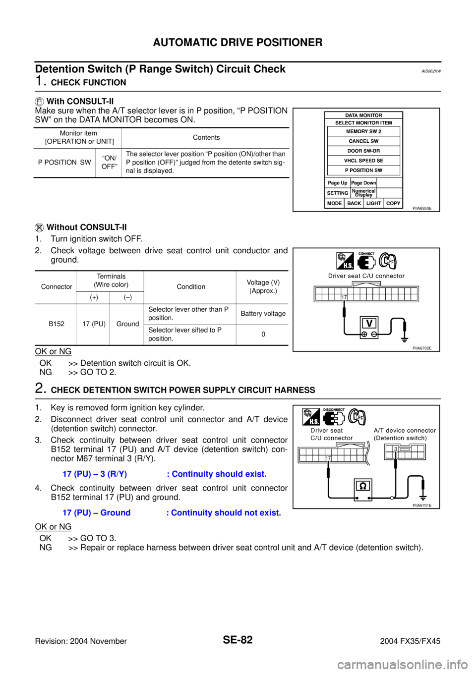
1. CHECK FUNCTION
With CONSULT-II
Make sure when the A/T selector lever is in P position, “P POSITION
SW” on the DATA MONITOR becomes ON.
Without CONSULT-II
1. Turn ignition switch OFF.
2. Check voltage between drive seat control unit conductor and
ground.
OK or NG
OK >> Detention switch circuit is OK.
NG >> GO TO 2.
2. CHECK DETENTION SWITCH POWER SUPPLY CIRCUIT HARNESS
1. Key is removed form ignition key cylinder.
2. Disconnect driver seat control unit connector and A/T device
(detention switch) connector.
3. Check continuity between driver seat control unit connector
B152 terminal 17 (PU) and A/T device (detention switch) con-
nector M67 terminal 3 (R/Y).
4. Check continuity between driver seat control unit connector
B152 terminal 17 (PU) and ground.
OK or NG
OK >> GO TO 3.
NG >> Repair or replace harness between driver seat control unit and A/T device (detention switch).
Monitor item
[OPERATION or UNIT]Contents
P POSITION SW“ON/
OFF”The selector lever position “P position (ON)/other than
P position (OFF)” judged from the detente switch sig-
nal is displayed.
PIIA6950E
ConnectorTerminals
(Wire color)
ConditionVoltage (V)
(Approx.)
(+) (–)
B152 17 (PU) GroundSelector lever other than P
position.Battery voltage
Selector lever sifted to P
position.0
PIIA6702E
17 (PU) – 3 (R/Y) : Continuity should exist.
17 (PU) – Ground : Continuity should not exist.
PIIA6701E
Page 4212 of 4449
AUTOMATIC DRIVE POSITIONER
SE-83
C
D
E
F
G
H
J
K
L
MA
B
SE
Revision: 2004 November 2004 FX35/FX45
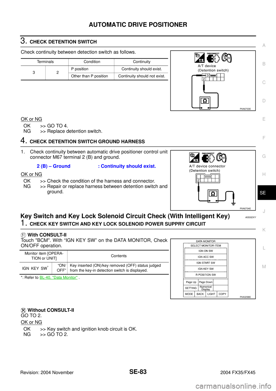
3. CHECK DETENTION SWITCH
Check continuity between detection switch as follows.
OK or NG
OK >> GO TO 4.
NG >> Replace detention switch.
4. CHECK DETENTION SWITCH GROUND HARNESS
1. Check continuity between automatic drive positioner control unit
connector M67 terminal 2 (B) and ground.
OK or NG
OK >> Check the condition of the harness and connector.
NG >> Repair or replace harness between detention switch and
ground.
Key Switch and Key Lock Solenoid Circuit Check (With Intelligent Key)AIS002XY
1. CHECK KEY SWITCH AND KEY LOCK SOLENOID POWER SUPPRY CIRCUIT
With CONSULT-II
Touch "BCM". With “IGN KEY SW” on the DATA MONITOR, Check
ON/OFF operation.
*: Refer to BL-40, "Data Monitor" .
Without CONSULT-II
GO TO 2.
OK or NG
OK >> Key switch and ignition knob circuit is OK.
NG >> GO TO 2.
Terminals Condition Continuity
32P position Continuity should exist.
Other than P position Continuity should not exist.
PIIA6703E
2 (B) – Ground : Continuity should exist.
PIIA6704E
Monitor item [OPERA-
TION or UNIT]Contents
IGN KEY SW
*“ON/
OFF”Key inserted (ON)/key removed (OFF) status judged
from the key-in detection switch is displayed.
PIIA0298E
Page 4213 of 4449
SE-84
AUTOMATIC DRIVE POSITIONER
Revision: 2004 November 2004 FX35/FX45
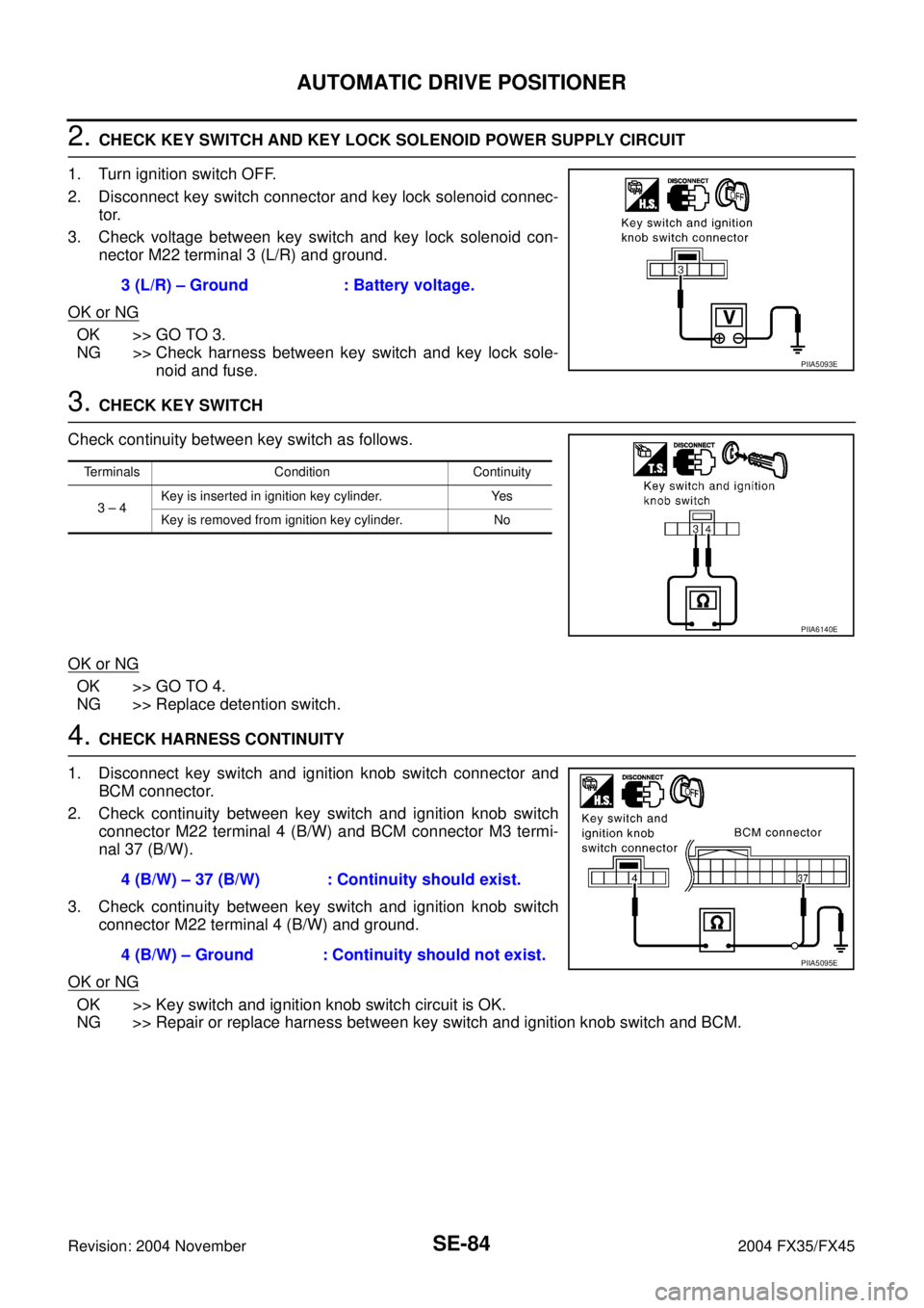
2. CHECK KEY SWITCH AND KEY LOCK SOLENOID POWER SUPPLY CIRCUIT
1. Turn ignition switch OFF.
2. Disconnect key switch connector and key lock solenoid connec-
tor.
3. Check voltage between key switch and key lock solenoid con-
nector M22 terminal 3 (L/R) and ground.
OK or NG
OK >> GO TO 3.
NG >> Check harness between key switch and key lock sole-
noid and fuse.
3. CHECK KEY SWITCH
Check continuity between key switch as follows.
OK or NG
OK >> GO TO 4.
NG >> Replace detention switch.
4. CHECK HARNESS CONTINUITY
1. Disconnect key switch and ignition knob switch connector and
BCM connector.
2. Check continuity between key switch and ignition knob switch
connector M22 terminal 4 (B/W) and BCM connector M3 termi-
nal 37 (B/W).
3. Check continuity between key switch and ignition knob switch
connector M22 terminal 4 (B/W) and ground.
OK or NG
OK >> Key switch and ignition knob switch circuit is OK.
NG >> Repair or replace harness between key switch and ignition knob switch and BCM.3 (L/R) – Ground : Battery voltage.
PIIA5093E
Terminals Condition Continuity
3 – 4Key is inserted in ignition key cylinder. Yes
Key is removed from ignition key cylinder. No
PIIA6140E
4 (B/W) – 37 (B/W) : Continuity should exist.
4 (B/W) – Ground : Continuity should not exist.
PIIA5095E
Page 4214 of 4449
AUTOMATIC DRIVE POSITIONER
SE-85
C
D
E
F
G
H
J
K
L
MA
B
SE
Revision: 2004 November 2004 FX35/FX45
Key Switch Circuit Check (Without Intelligent Key)AIS003G1
1. CHECK KEY SWITCH
With CONSULT-II
Touch "BCM". With “IGN KEY SW” on the DATA MONITOR, Check
ON/OFF operation.
*:Refer to BL-40, "Data Monitor" .
Without CONSULT-II
GO TO 2.
OK or NG
OK >> Key switch circuit is OK.
NG >> GO TO 2.
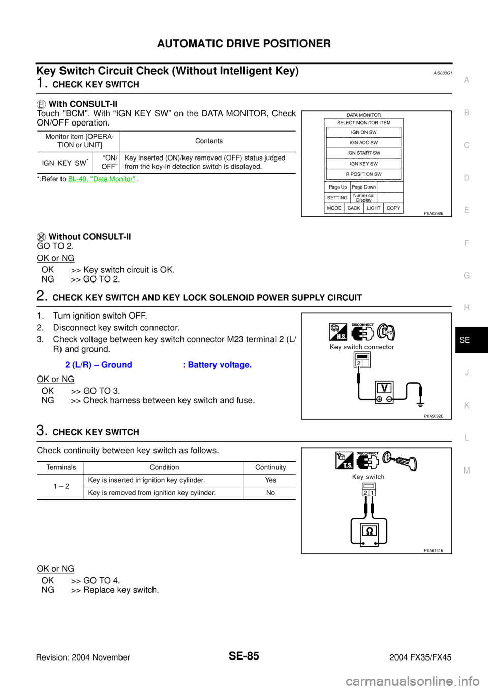
2. CHECK KEY SWITCH AND KEY LOCK SOLENOID POWER SUPPLY CIRCUIT
1. Turn ignition switch OFF.
2. Disconnect key switch connector.
3. Check voltage between key switch connector M23 terminal 2 (L/
R) and ground.
OK or NG
OK >> GO TO 3.
NG >> Check harness between key switch and fuse.
3. CHECK KEY SWITCH
Check continuity between key switch as follows.
OK or NG
OK >> GO TO 4.
NG >> Replace key switch.
Monitor item [OPERA-
TION or UNIT]Contents
IGN KEY SW
*“ON/
OFF”Key inserted (ON)/key removed (OFF) status judged
from the key-in detection switch is displayed.
PIIA0298E
2 (L/R) – Ground : Battery voltage.
PIIA5092E
Terminals Condition Continuity
1 – 2Key is inserted in ignition key cylinder. Yes
Key is removed from ignition key cylinder. No
PIIA6141E
Page 4215 of 4449
SE-86
AUTOMATIC DRIVE POSITIONER
Revision: 2004 November 2004 FX35/FX45
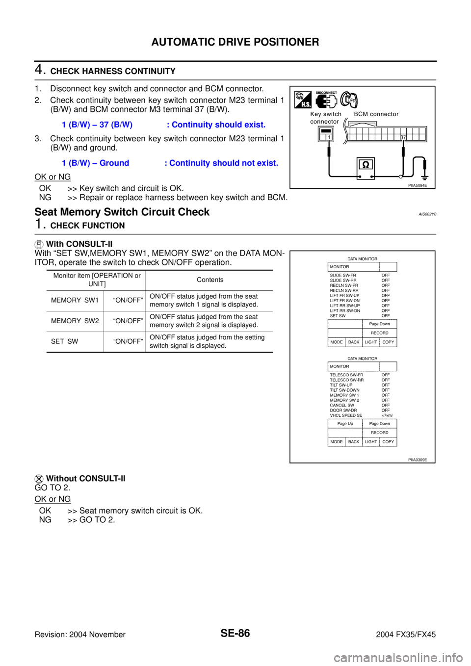
4. CHECK HARNESS CONTINUITY
1. Disconnect key switch and connector and BCM connector.
2. Check continuity between key switch connector M23 terminal 1
(B/W) and BCM connector M3 terminal 37 (B/W).
3. Check continuity between key switch connector M23 terminal 1
(B/W) and ground.
OK or NG
OK >> Key switch and circuit is OK.
NG >> Repair or replace harness between key switch and BCM.
Seat Memory Switch Circuit CheckAIS002Y0
1. CHECK FUNCTION
With CONSULT-II
With “SET SW,MEMORY SW1, MEMORY SW2” on the DATA MON-
ITOR, operate the switch to check ON/OFF operation.
Without CONSULT-II
GO TO 2.
OK or NG
OK >> Seat memory switch circuit is OK.
NG >> GO TO 2.1 (B/W) – 37 (B/W) : Continuity should exist.
1 (B/W) – Ground : Continuity should not exist.
PIIA5094E
Monitor item [OPERATION or
UNIT]Contents
MEMORY SW1 “ON/OFF”ON/OFF status judged from the seat
memory switch 1 signal is displayed.
MEMORY SW2 “ON/OFF”ON/OFF status judged from the seat
memory switch 2 signal is displayed.
SET SW “ON/OFF”ON/OFF status judged from the setting
switch signal is displayed.
PIIA0309E