Page 1000 of 4449
VEHICLE SECURITY (THEFT WARNING) SYSTEM
BL-193
C
D
E
F
G
H
J
K
L
MA
B
BL
Revision: 2004 November 2004 FX35/FX45
CONSULT-II Inspection ProcedureAIS004P0
CAUTION:
CONSULT-II is used with no connection of CONSULT-II CONVERTER, malfunction might be detected in
self-diagnosis depending on control unit with carry out CAN communication.
1. Turn ignition switch OFF.
2. Connect CONSULT-II and CONSULT-II CONVERTER to data
link connector.
3. Turn ignition switch ON.
4. Touch “START (NISSAN BASED VHCL)”.
5. Touch “BCM”.
If “BCM” is not indicated, go to GI-40, "
CONSULT-II Data Link
Connector (DLC) Circuit" .
6. Touch “THEFT ALM”.
PBIB1503E
MBIB0233E
LIIA0033E
LIIA0034E
Page 1001 of 4449

BL-194
VEHICLE SECURITY (THEFT WARNING) SYSTEM
Revision: 2004 November 2004 FX35/FX45
7. Select diagnosis mode.
“DATA MONITOR”, “ACTIVE TEST” AND “WORK SUPPORT”
CONSULT-II APPLICATION ITEM
Work Support
Data Monitor
Active Test
SEL274W
Test Item Description
SECURITY ALARM SET This mode is able to confirm and change security alarm ON-OFF setting.
THEFT ALM TRGThe switch which triggered vehicle security alarm is recorded. This mode is able to confirm and
erase the record of vehicle security alarm. The trigger data can be erased by touching “CLEAR”
on CONSULT-II screen.
Monitored Item Description
IGN ON SW Indicates [ON/OFF] condition of ignition switch.
ACC ON SW Indicates [ON/OFF] condition of ignition switch in ACC position.
KEY ON SW Indicates [ON/OFF] condition of key switch.
TRUNK OPNR SW This is displayed even when it is not equipped.
TRUNK CYL SW This is displayed even when it is not equipped.
TRUNK OPN MNTR This is displayed even when it is not equipped.
KEYLESS LOCK Indicates [ON/OFF] condition of lock signal from key fob.
KEYLESS UNLOCK Indicates [ON/OFF] condition of unlock signal from key fob.
KEYLESS TRUNK Indicates [ON/OFF] condition of trunk opener signal from key fob.
HOOD SW Indicates [ON/OFF] condition of hood switch.
DOOR SW-DR Indicates [ON/OFF] condition of front door switch LH.
DOOR SW-AS Indicates [ON/OFF] condition of front door switch RH.
DOOR SW-RR Indicates [ON/OFF] condition of rear door switch RH.
DOOR SW-RL Indicates [ON/OFF] condition of rear door switch LH.
BACK DOOR SW Indicates [ON/OFF] condition of back door switch.
KEY CYL LK SW Indicates [ON/OFF] condition of lock signal from key cylinder switch.
KEY CYL UN SW Indicates [ON/OFF] condition of unlock signal from key cylinder switch.
CDL LOCK SW Indicates [ON/OFF] condition of lock signal from door lock/unlock switch LH and RH.
CDL UNLOCK SW Indicates [ON/OFF] condition of unlock signal from door lock/unlock switch LH and RH.
Test Item Description
THEFT INDThis test is able to check security indicator lamp operation. The lamp will be turned on when “ON”
on CONSULT-II screen is touched.
ANTI THEFT HORNThis test is able to check vehicle security horn operation. The horns will be activated for 0.5 sec-
onds after “ON” on CONSULT-II screen is touched.
HEADLAMP(HI)This test is able to check vehicle security lamp operation. The headlamps will be activated for 0.5
seconds after “ON” on CONSULT-II screen is touched.
Page 1003 of 4449
BL-196
VEHICLE SECURITY (THEFT WARNING) SYSTEM
Revision: 2004 November 2004 FX35/FX45
Preliminary CheckAIS004P2
The system operation is canceled by turning ignition switch to “ACC” at any step between START and ARMED
in the following flow chart.
After performing preliminary check, go to symptom chart. Refer to BL-197, "
Trouble Diagnosis Symptom
Chart" .
PIIA6910E
Page 1006 of 4449

VEHICLE SECURITY (THEFT WARNING) SYSTEM
BL-199
C
D
E
F
G
H
J
K
L
MA
B
BL
Revision: 2004 November 2004 FX35/FX45
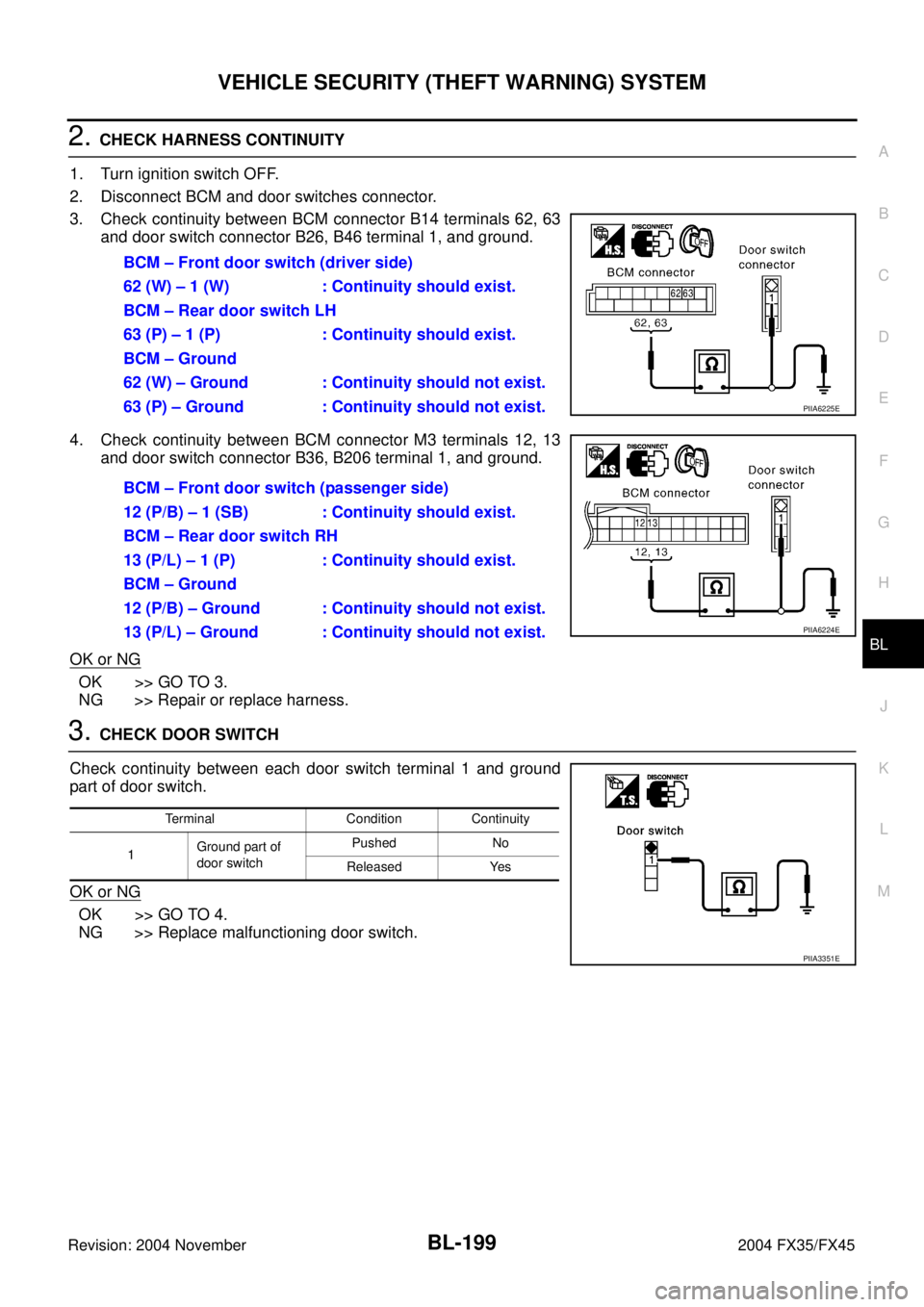
2. CHECK HARNESS CONTINUITY
1. Turn ignition switch OFF.
2. Disconnect BCM and door switches connector.
3. Check continuity between BCM connector B14 terminals 62, 63
and door switch connector B26, B46 terminal 1, and ground.
4. Check continuity between BCM connector M3 terminals 12, 13
and door switch connector B36, B206 terminal 1, and ground.
OK or NG
OK >> GO TO 3.
NG >> Repair or replace harness.
3. CHECK DOOR SWITCH
Check continuity between each door switch terminal 1 and ground
part of door switch.
OK or NG
OK >> GO TO 4.
NG >> Replace malfunctioning door switch.BCM – Front door switch (driver side)
62 (W) – 1 (W) : Continuity should exist.
BCM – Rear door switch LH
63 (P) – 1 (P) : Continuity should exist.
BCM – Ground
62 (W) – Ground : Continuity should not exist.
63 (P) – Ground : Continuity should not exist.
PIIA6225E
BCM – Front door switch (passenger side)
12 (P/B) – 1 (SB) : Continuity should exist.
BCM – Rear door switch RH
13 (P/L) – 1 (P) : Continuity should exist.
BCM – Ground
12 (P/B) – Ground : Continuity should not exist.
13 (P/L) – Ground : Continuity should not exist.
PIIA6224E
Terminal Condition Continuity
1Ground part of
door switchPushed No
Released Yes
PIIA3351E
Page 1008 of 4449
VEHICLE SECURITY (THEFT WARNING) SYSTEM
BL-201
C
D
E
F
G
H
J
K
L
MA
B
BL
Revision: 2004 November 2004 FX35/FX45
3. CHECK HOOD SWITCH
1. Turn ignition switch OFF.
2. Disconnect hood switch connector.
3. Check continuity between hood switch terminals 1 and 2.
OK or NG
OK >> GO TO 4.
NG >> Replace hood switch.
4. CHECK IPDM E/R OUTPUT SIGNAL
Check voltage between IPDM E/R connector and ground.
OK or NG
OK >> Check the following.
�Hood switch ground circuit.
�Harness for open or short between hood switch and
IPDM E/R.
NG >> Replace IPDM E/R
Terminals Condition Continuity
1 2Pressed No
Released Yes
PIIA2498E
ConnectorTerminals (Wire color)
ConditionVoltage (V)
(Approx.)
(+) (-)
E9 56 (LG) GroundOPEN 0
CLOSE Battery voltage
PIIA6228E
Page 1009 of 4449

BL-202
VEHICLE SECURITY (THEFT WARNING) SYSTEM
Revision: 2004 November 2004 FX35/FX45
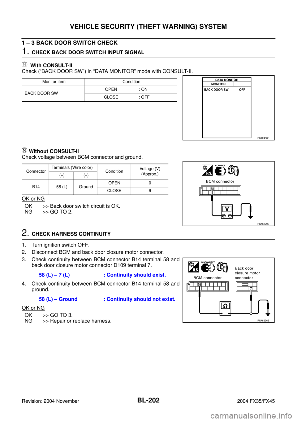
1 – 3 BACK DOOR SWITCH CHECK
1. CHECK BACK DOOR SWITCH INPUT SIGNAL
With CONSULT-II
Check (“BACK DOOR SW”) in “DATA MONITOR” mode with CONSULT-II.
Without CONSULT-II
Check voltage between BCM connector and ground.
OK or NG
OK >> Back door switch circuit is OK.
NG >> GO TO 2.
2. CHECK HARNESS CONTINUITY
1. Turn ignition switch OFF.
2. Disconnect BCM and back door closure motor connector.
3. Check continuity between BCM connector B14 terminal 58 and
back door closure motor connector D109 terminal 7.
4. Check continuity between BCM connector B14 terminal 58 and
ground.
OK or NG
OK >> GO TO 3.
NG >> Repair or replace harness.
Monitor item Condition
BACK DOOR SWOPEN : ON
CLOSE : OFF
PIIA2488E
ConnectorTerminals (Wire color)
ConditionVoltage (V)
(Approx.)
(+) (–)
B14 58 (L) GroundOPEN 0
CLOSE 9
PIIA6229E
58 (L) – 7 (L) : Continuity should exist.
58 (L) – Ground : Continuity should not exist.
PIIA6226E
Page 1011 of 4449

BL-204
VEHICLE SECURITY (THEFT WARNING) SYSTEM
Revision: 2004 November 2004 FX35/FX45
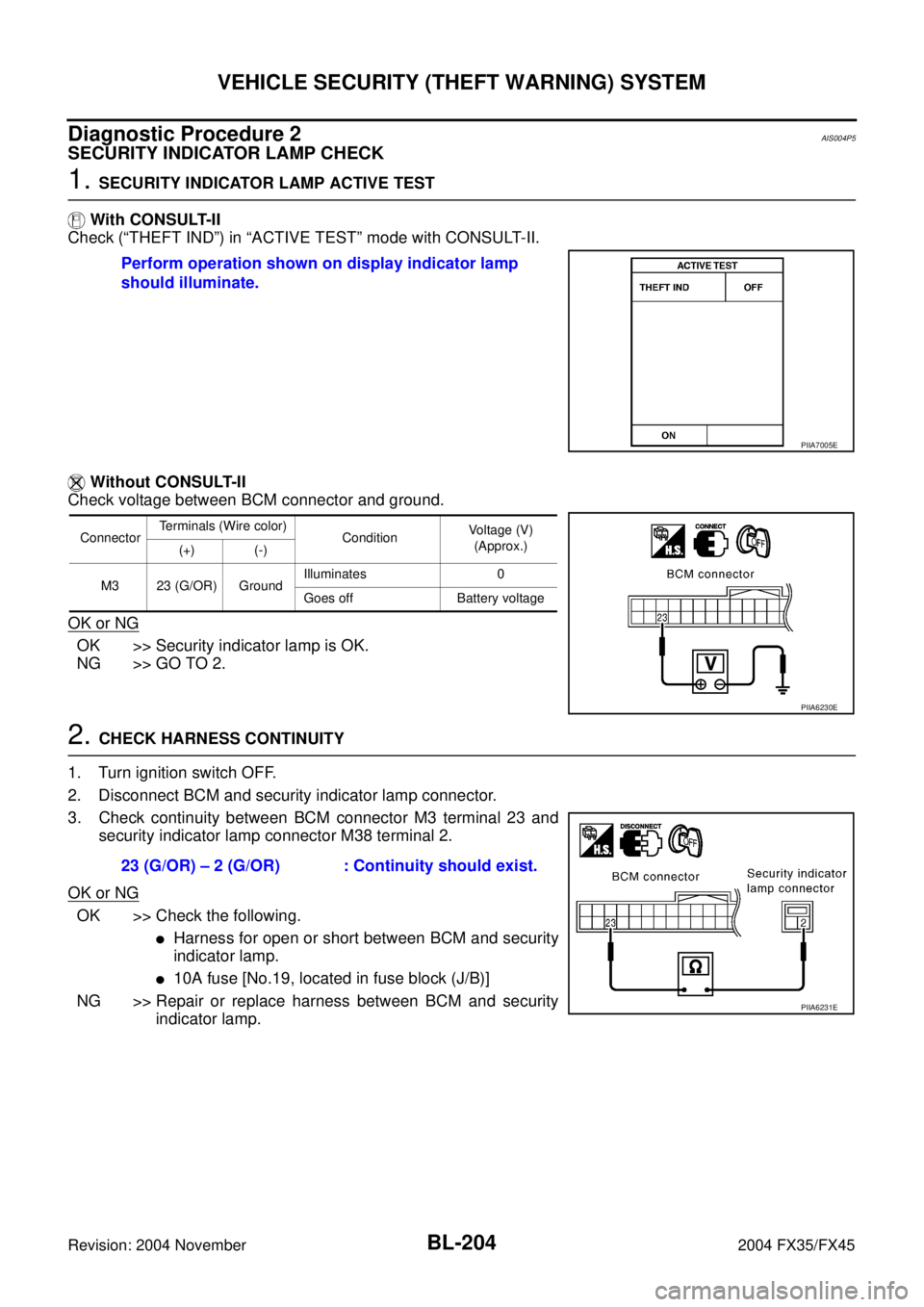
Diagnostic Procedure 2AIS004P5
SECURITY INDICATOR LAMP CHECK
1. SECURITY INDICATOR LAMP ACTIVE TEST
With CONSULT-II
Check (“THEFT IND”) in “ACTIVE TEST” mode with CONSULT-II.
Without CONSULT-II
Check voltage between BCM connector and ground.
OK or NG
OK >> Security indicator lamp is OK.
NG >> GO TO 2.
2. CHECK HARNESS CONTINUITY
1. Turn ignition switch OFF.
2. Disconnect BCM and security indicator lamp connector.
3. Check continuity between BCM connector M3 terminal 23 and
security indicator lamp connector M38 terminal 2.
OK or NG
OK >> Check the following.
�Harness for open or short between BCM and security
indicator lamp.
�10A fuse [No.19, located in fuse block (J/B)]
NG >> Repair or replace harness between BCM and security
indicator lamp. Perform operation shown on display indicator lamp
should illuminate.
PIIA7005E
ConnectorTerminals (Wire color)
ConditionVoltage (V)
(Approx.)
(+) (-)
M3 23 (G/OR) GroundIlluminates 0
Goes off Battery voltage
PIIA6230E
23 (G/OR) – 2 (G/OR) : Continuity should exist.
PIIA6231E
Page 1013 of 4449
BL-206
IVIS (INFINITI VEHICLE IMMOBILIZER SYSTEM-NATS)
Revision: 2004 November 2004 FX35/FX45
IVIS (INFINITI VEHICLE IMMOBILIZER SYSTEM-NATS)PFP:28591
Component Parts and Harness Connector LocationAIS004PA
NOTE:
If customer reports a “NO START” condition, request ALL ignition key (without intelligent key system) or
mechanical key (with intelligent key system) to be brought to the dealer to check for a NATS malfunction.
System DescriptionAIS004PB
DESCRIPTION
IVIS (Infiniti Vehicle Immobilizer System – NATS) has the following immobilizer functions:
�Engine immobilizer shows high anti-theft performance to prevent engine start by other than the owner
(registered key: ignition key, mechanical key and Intelligent Key).
�Only a key with key ID registered in BCM and ECM can start engine, and shows high anti-theft perfor-
mance to prevent key from being copied or stolen.
PIIA6649E