Page 4090 of 4449

SC-1
STARTING & CHARGING SYSTEM
K ELECTRICAL
CONTENTS
C
D
E
F
G
H
I
J
L
M
SECTION SC
A
B
SC
Revision: 2004 November 2004 FX35/FX45
STARTING & CHARGING SYSTEM
PRECAUTIONS .......................................................... 2
Precautions for Supplemental Restraint System
(SRS) “AIR BAG” and “SEAT BELT PRE-TEN-
SIONER” .................................................................. 2
Wiring Diagrams and Trouble Diagnosis .................. 2
PREPARATION ........................................................... 3
Special Service Tools ............................................... 3
Commercial Service Tools ........................................ 3
BATTERY .................................................................... 4
How to Handle Battery ............................................. 4
METHODS OF PREVENTING OVER-DIS-
CHARGE ............................................................... 4
CHECKING ELECTROLYTE LEVEL .................... 5
SPECIFIC GRAVITY CHECK ............................... 5
CHARGING THE BATTERY ................................. 6
Trouble Diagnosis with Battery/Starting/Charging
System Tester .......................................................... 6
DIAGNOSTIC RESULT ITEM CHART .................. 8
Removal and Installation .......................................... 9
REMOVAL ............................................................. 9
INSTALLATION ..................................................... 9
STARTING SYSTEM ................................................ 10
System Description ................................................ 10
Wiring Diagram — START — .................................. 11
VK45DE ENGINE MODELS ................................ 11
VQ35DE ENGINE MODELS ............................... 12
Trouble Diagnosis with Battery/Starting/Charging
System Tester ........................................................ 13
DIAGNOSTIC RESULT ITEM CHART ................ 13
WORK FLOW ...................................................... 14
DIAGNOSTIC PROCEDURE 1 ........................... 15
DIAGNOSTIC PROCEDURE 2 ........................... 16
MINIMUM SPECIFICATION OF CRANKING VOLTAGE REFERENCING COOLANT TEM-
PERATURE ......................................................... 16
Removal and Installation ........................................ 17
VK45DE ENGINE MODELS ................................ 17
VQ35DE ENGINE MODELS (2WD) .................... 18
VQ35DE ENGINE MODELS (AWD) .................... 19
Disassembly and Assembly .................................... 20
Inspection After Disassembly ................................. 22
PINION/CLUTCH CHECK ................................... 22
CHARGING SYSTEM ............................................... 23
System Description ................................................. 23
Wiring Diagram — CHARGE — ............................. 24
VK45DE ENGINE MODELS ................................ 24
VQ35DE ENGINE MODELS ............................... 25
Trouble Diagnosis with Battery/Starting/Charging
System Tester ......................................................... 26
DIAGNOSTIC RESULT ITEM CHART ................ 27
WORK FLOW ...................................................... 28
DIAGNOSTIC PROCEDURE 1 ........................... 29
DIAGNOSTIC PROCEDURE 2 ........................... 30
DIAGNOSTIC PROCEDURE 3 ........................... 31
DIAGNOSTIC PROCEDURE 4 ........................... 32
DIAGNOSTIC PROCEDURE 5 ........................... 33
MALFUNCTION INDICATOR .............................. 33
Removal and Installation ........................................ 34
VK45DE ENGINE MODELS ................................ 34
VQ35DE ENGINE MODELS ............................... 35
Disassembly and Assembly .................................... 37
SERVICE DATA AND SPECIFICATIONS (SDS) ...... 39
Battery .................................................................... 39
Starter ..................................................................... 39
Alternator ................................................................ 39
Page 4121 of 4449

SC-32
CHARGING SYSTEM
Revision: 2004 November 2004 FX35/FX45
DIAGNOSTIC PROCEDURE 4
Check “B” Terminal Circuit
1. CHECK “B” TERMINAL CONNECTION
1. Turn ignition switch OFF.
2. Check to see if “B” terminal is clean and tight.
OK or NG
OK >> GO TO 2. Confirm repair by performing complete Battery/Starting/Charging system test.
NG >> Repair “B” terminal connection.
2. CHECK ALTERNATOR “B” TERMINAL CIRCUIT
Check voltage between alternator B terminal E307 terminal 1 (B/R)
and ground using a digital circuit tester.
OK or NG
OK >> GO TO 3.
NG >> Check the following.
�120A fusible link [fusible link holder (VK45DE and
VQ35DE AWD)]
�Harness for open or short between alternator and fus-
ible link (VK45DE and VQ35DE AWD)
�Harness for open or short between alternator and battery (VQ35DE 2WD)
3. CHECK “B” TERMINAL CONNECTION (VOLTAGE DROP TEST)
1. Start the engine.
2. When the engine running at idle and warm, check voltage
between alternator B terminal E307 terminal 1 (B/R) and battery
positive terminal using a digital circuit tester.
OK or NG
OK >> GO TO 4.
NG >> Check harness between the battery and the alternator
for poor continuity.
4. CHECK ALTERNATOR DRIVE BELT TENSION
1. Turn ignition switch OFF.
2. Check alternator drive belt tension. Refer to EM-169, "
Checking Drive Belts" (VK45DE) or EM-15,
"Checking Drive Belts" (VQ35DE) in “ENGINE MECHANICAL (EM)” section.
YES or NO
YES >> Replace the alternator. Confirm repair by performing complete Battery/Starting/Charging system
test.
NO >> Readjust drive belt tension. Refer to EM-169, "
Tension Adjustment" (VK45DE) or EM-15, "Te n -
sion Adjustment" (VQ35DE) in “ENGINE MECHANICAL (EM)” section. Battery voltage should exist.
PKIA2944E
Voltage: Less than 0.2V
PKIA2366E
Does drive belt tension normal?
Page 4123 of 4449

SC-34
CHARGING SYSTEM
Revision: 2004 November 2004 FX35/FX45
Removal and Installation AKS00816
VK45DE ENGINE MODELS
Removal
1. Disconnect negative battery cable.
2. Remove engine front undercover, using power tools.
3. Remove cooling fan lower shroud. Refer to CO-39, "
RADIATOR" in “ENGINE COOLING SYSTEM (CO)”
section.
4. Remove alternator, water pump and A/C compressor belt. Refer to EM-169, "
Removal and Installation" in
“ENGINE MECHANICAL (EM)” section.
5. Remove alternator mounting bolts, using power tools.
6. Disconnect alternator connector.
7. Remove B terminal nut.
8. Remove alternator ground harness mounting bolt.
9. Remove alternator assembly to the direction of under side the
vehicle.
1. Alternator ground harness mounting bolt 2. B terminal nut 3. Alternator B terminal harness
4. Alternator Nut 5. Alternator bracket 6. Alternator connector
7. Alternator 8. Alternator mounting bolt 9. Alternator stay
10. Alternator mounting bolt 11. Alternator stay mounting bolt 12. Alternator ground harness
PKIA2818E
PKIA2954E
PKIA2820E
Page 4124 of 4449
CHARGING SYSTEM
SC-35
C
D
E
F
G
H
I
J
L
MA
B
SC
Revision: 2004 November 2004 FX35/FX45
Installation
Note the following, and install in the reverse order of removal.
�Install alternator, and check tension of belt. Refer to EM-169, "Checking Drive Belts" in “ENGINE
MECHANICAL (EM)” section.
CAUTION:
Be sure to tighten B terminal nut carefully.
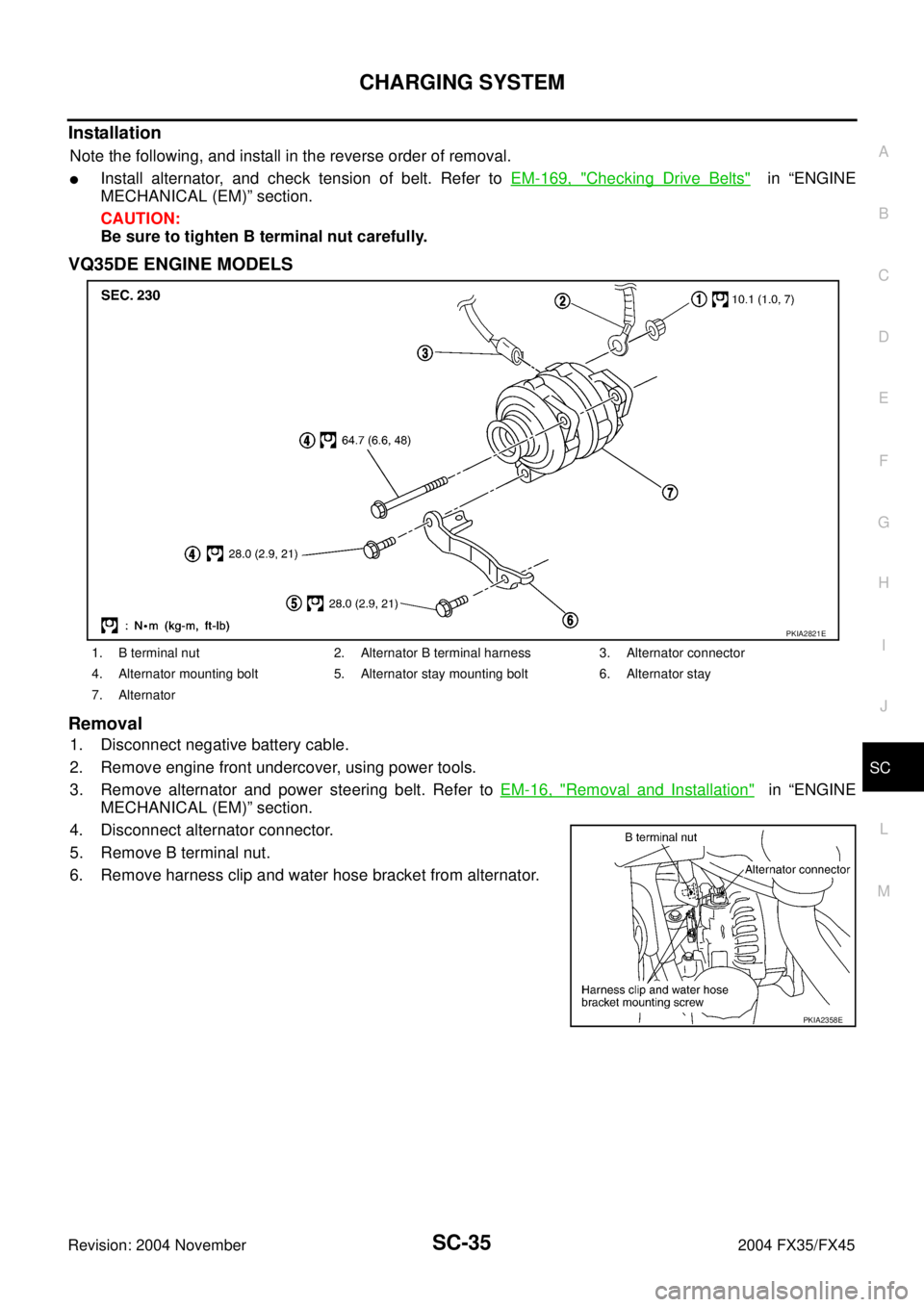
VQ35DE ENGINE MODELS
Removal
1. Disconnect negative battery cable.
2. Remove engine front undercover, using power tools.
3. Remove alternator and power steering belt. Refer to EM-16, "
Removal and Installation" in “ENGINE
MECHANICAL (EM)” section.
4. Disconnect alternator connector.
5. Remove B terminal nut.
6. Remove harness clip and water hose bracket from alternator.
1. B terminal nut 2. Alternator B terminal harness 3. Alternator connector
4. Alternator mounting bolt 5. Alternator stay mounting bolt 6. Alternator stay
7. Alternator
PKIA2821E
PKIA2358E
Page 4125 of 4449
SC-36
CHARGING SYSTEM
Revision: 2004 November 2004 FX35/FX45
7. Remove oil pressure switch harness clip from alternator stay.
(2WD)
8. Disconnect oil pressure switch connector. (2WD)
9. Remove alternator stay mounting bolts and alternator stay, using
power tools.
10. Remove alternator mounting bolt, using power tools.
11. Remove alternator assembly to the direction of under side the vehicle.
Installation
Note the following, and install in the reverse order of removal.
�Install alternator, and check tension of belt. Refer to EM-15, "Checking Drive Belts" in “ENGINE
MECHANICAL (EM)” section.
CAUTION:
Be sure to tighten B terminal nut carefully.
PKIA1923E
Page:
< prev 1-8 9-16 17-24

8. Disconnect oil pressure switch connector. (2WD)
9. Remove alterna")