Page 3089 of 4449
FSU-4
PREPARATION
Revision: 2004 November 2004 FX35/FX45
Commercial Service ToolsAES000N1
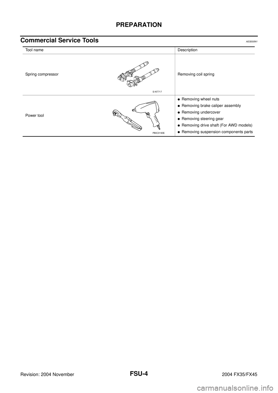
Tool nameDescription
Spring compressor Removing coil spring
Power tool
�Removing wheel nuts
�Removing brake caliper assembly
�Removing undercover
�Removing steering gear
�Removing drive shaft (For AWD models)
�Removing suspension components parts
S-NT717
PBIC0190E
Page 3094 of 4449

FRONT SUSPENSION ASSEMBLY
FSU-9
C
D
F
G
H
I
J
K
L
MA
B
FSU
Revision: 2004 November 2004 FX35/FX45
Removal and InstallationAES000N6
REMOVAL
1. Set an engine slinger to engine, then suspend engine.
2. Remove tire from vehicle with power tool.
3. Remove brake caliper with power tool. Hang it in a place where it will not interfere with work. Refer to BR-
20, "FRONT DISC BRAKE" .
4. Remove brake hose lock plate. Then remove brake hose from
strut assembly.
5. Remove disc rotor.
6. Remove wheel sensor harness from strut assembly.
CAUTION:
Do not pull on wheel sensor harness.
7. Remove undercover with power tool.
8. Remove front cross bar.
9. Remove steering hydraulic piping bracket from front suspension
member. Refer to PS-41, "
HYDRAULIC LINE" .
10. Remove cotter pin at steering outer socket, then loosen mount-
ing nut.
11. Use a ball joint remover (SST) to remove steering outer socket
from steering knuckle. Be careful not to damage ball joint boot.
CAUTION:
Tighten temporarily mounting nut to prevent damage to
threads and to prevent ball joint remover (SST) from com-
ing off.
12. Remove mounting bolts of steering gear with power tool, then
hang steering gear on vehicle. Refer to PS-19, "
POWER
STEERING GEAR AND LINKAGE" .
13. Remove front final drive side of drive shaft with power tool. (For
AWD models) Refer to FAX-12, "
Removal and Installation (Left
Side)" , FA X - 1 3 , "Removal and Installation (Right Side)" .
14. Set jack under front suspension member.
15. Remove fixing bolts and nuts between strut assembly and steering knuckle with power tool.
1. Strut upper plate 2. Strut spacer 3. Mounting insulator
4. Mounting insulator bracket 5. Mounting bearing 6. Spring upper seat
7. Spring upper rubber seat 8. Coil spring 9. Spring lower rubber seat
10. Bound bumper 11. Strut 12. Steering knuckle
13. Front suspension member 14. Transverse link 15. Stabilizer bar
16. Stabilizer bushing 17. Stabilizer clamp 18. Stabilizer connecting rod
19. Front cross bar 20. Cotter pin
SEIA0328E
SEIA0329E
SDIA1434E
Page 3822 of 4449
CHASSIS AND BODY MAINTENANCE
MA-35
C
D
E
F
G
H
I
J
K
MA
B
MA
Revision: 2004 November 2004 FX35/FX45
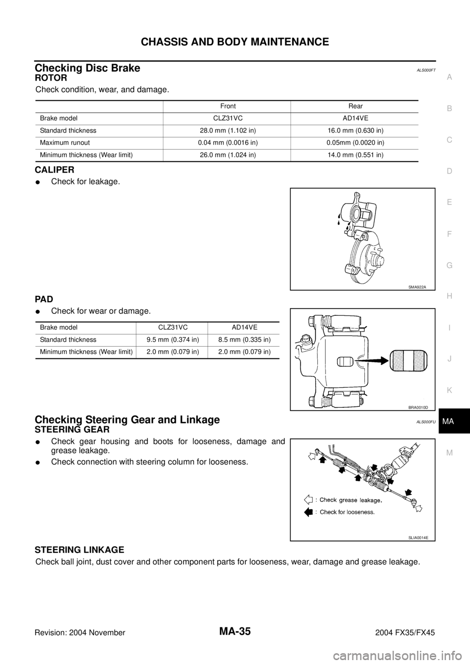
Checking Disc BrakeALS000FT
ROTOR
Check condition, wear, and damage.
CALIPER
�Check for leakage.
PA D
�Check for wear or damage.
Checking Steering Gear and LinkageALS000FU
STEERING GEAR
�Check gear housing and boots for looseness, damage and
grease leakage.
�Check connection with steering column for looseness.
STEERING LINKAGE
Check ball joint, dust cover and other component parts for looseness, wear, damage and grease leakage.
Front Rear
Brake model CLZ31VC AD14VE
Standard thickness 28.0 mm (1.102 in) 16.0 mm (0.630 in)
Maximum runout 0.04 mm (0.0016 in) 0.05mm (0.0020 in)
Minimum thickness (Wear limit) 26.0 mm (1.024 in) 14.0 mm (0.551 in)
SMA922A
Brake model CLZ31VC AD14VE
Standard thickness 9.5 mm (0.374 in) 8.5 mm (0.335 in)
Minimum thickness (Wear limit) 2.0 mm (0.079 in) 2.0 mm (0.079 in)
BRA0010D
SLIA0014E
Page 3830 of 4449

PARKING BRAKE CONTROL
PB-3
C
D
E
G
H
I
J
K
L
MA
B
PB
Revision: 2004 November 2004 FX35/FX45
PARKING BRAKE CONTROLPFP:36010
ComponentsAFS001TK
Removal and InstallationAFS001TL
REMOVAL
1. Remove front kicking plate (driver side). Refer to IP-12, "(A) Front Kicking Plate (LH/RH)" .
2. Remove front body side welt (driver side). Refer to EI-37, "
BODY SIDE TRIM" .
3. Remove dash side finisher (driver side). Refer to IP-10, "
INSTRUMENT PANEL ASSEMBLY" .
4. Remove instrument lower panel (driver side). Refer to IP-10, "
INSTRUMENT PANEL ASSEMBLY" .
5. Remove adjusting nut.
6. Remove front cable installation bolts, nuts, and lock plate, then remove front cable from the vehicle.
7. Remove heat insulator between center tube and rear propeller shaft.
8. Remove exhaust center muffler. Refer to EX-3, "
EXHAUST SYSTEM" .
9. Remove propeller shaft. Refer to PR-7, "
Removal and Installation" .
10. Remove rear disc caliper and disc rotors. Refer to BR-26, "
Removal and Installation of Brake Caliper
Assembly" .
11. Remove parking brake shoe, and remove rear cable from toggle lever. Refer to PB-5, "
PARKING BRAKE
SHOE" .
1. Device assembly 2. Spring insulator 3. Return spring
4. Lock plate 5. Front cable 6. Return spring
7. Rear left cable 8. Rear right cable 9. Pin
10. Adjusting nut
SFIA1943E
Page 3833 of 4449

PB-6
PARKING BRAKE SHOE
Revision: 2004 November 2004 FX35/FX45
INSPECTION AFTER REMOVAL
Lining Thickness Inspection
�Check thickness of lining.
Drum Inner Diameter Inspection
�Check drum inner diameter.
Other Inspections
�Check shoe sliding surface for excessive wear and damage.
�Check anti-rattle pin for excessive wear and corrosion.
�Check return spring for sagging.
�Check adjustor for rough operation.
�Check either visually or with a vernier caliper to see if there is
any excessive wear, cracks, or damage inside drum.
INSTALLATION
Be careful of the following:
�Refer to “Component Parts Location” and apply brake grease to the specified points during assembly.
�Assemble adjuster so that threaded part expands when rotating
it in the direction shown by the arrow.
�Shorten adjuster by rotating it.
�When disassembling adjuster, apply PBC (Poly Butyl Cuprysil)
grease or silicone based grease to the threads.
�After replacing brake shoes or disc rotors, or if brakes do not
function well, perform break-in operation as follows.
1. Adjust parking brake pedal stroke to the specified stroke.
2. Perform parking brake break-in (drag run) operation by driving
the vehicle under the following conditions:
3. After break-in operation, check lever stroke of parking brake. Readjust if it is no longer at the specified
stroke.
�To prevent lining from getting too hot, allow a cool off period of approximately 5 minutes after every
break-in operation.
�Do not perform excessive break-in operations, because it may cause uneven or early wear of lining.Standard thickness (A) : 3.2 mm (0.126 in)
Repair limit thickness (A) : 1.5 mm (0.059 in)
SBR021A
Standard inner diameter : 190 mm (7.48 in)
Maximum inner diameter : 191 mm (7.52 in)
SBR768A
Drive forward
�Perform the following
�Vehicle speed approx. 40 km/h (25 MPH) set (forward)
�Parking brake operating force approx. 100 N (10 kg, 45lb) set
�Distance approx. 100m (328ft)
SFIA0153E
Page 3984 of 4449
ADS000C1
The actual shapes of Kent-Moore tools may differ from those")
PREPARATION
RAX-3
C
E
F
G
H
I
J
K
L
MA
B
RAX
Revision: 2004 November 2004 FX35/FX45
PREPARATIONPFP:00002
Special Service Tools (SST)ADS000C1
The actual shapes of Kent-Moore tools may differ from those of special service tools illustrated here.
Commercial Service ToolsADS000C2
Tool number
(Kent-Moore No.)
Tool nameDescription
ST33251000
( — )
Drift
�Removing wheel hub
�Removing wheel bearing outer side
inner race
�Installing wheel hub
�Inspection of wheel bearing rotating
torque
ST35300000
( — )
Drift
a: 45 mm (1.77 in) dia.
b: 59 mm (2.32 in) dia.
�Installing wheel hub
�Inspection of wheel bearing rotating
torque
KV40100900
( — )
Drift
a: 52 mm (2.05 in) dia.
b: —Wheel bearing rotating torque
inspection
KV38100500
( — )
Drift
a: 80 mm (3.15 in) dia.
b: 60 mm (2.36 in) dia.Installing drive shaft plug
KV38102200
( — )
Drift
a: 90 mm (3.54 in) dia.
b: 31 mm (1.22 in) dia.Installing drive shaft plug
ZZA0982D
ZZA0881D
ZZA0539D
ZZA0701D
ZZA0920D
Tool nameDescription
Power tool
�Removing wheel nuts
�Removing brake caliper assembly
�Removing wheel hub and bearing
assembly
�Removing suspension links
�Removing drive shaft fixing bolts
and nutsPBIC0190E
Page 3986 of 4449
")
WHEEL HUB
RAX-5
C
E
F
G
H
I
J
K
L
MA
B
RAX
Revision: 2004 November 2004 FX35/FX45
WHEEL HUBPFP:43202
On-Vehicle Inspection and ServiceADS000C4
Make sure the mounting conditions (looseness, back lash) of each component and component status (wear,
damage) are normal.
WHEEL BEARING INSPECTION
�Move wheel hub in the axial direction by hand. Make sure there is no looseness of wheel bearing.
�Rotate wheel hub and make sure there is no unusual noise or other irregular conditions. If there are any
irregular conditions, replace wheel bearings.
Removal and InstallationADS000C5
REMOVAL
1. Remove tire with power tool.
2. Remove brake caliper with power tool. Hang it in a place where it will not interfere with work. Refer to BR-
26, "Removal and Installation of Brake Caliper Assembly" .
NOTE:
�Avoid depressing brake pedal while brake caliper is removed.
3. Remove disc rotor.
4. Remove wheel sensor from axle. Refer to BRC-57, "
WHEEL SENSORS" .
CAUTION:
Do not pull on wheel sensor harness.
5. Remove cotter pin. Then remove lock nut from drive shaft.
6. Separate drive shaft from wheel hub and bearing assembly by lightly tapping the end with a suitable ham-
mer and wood block. If it is hard to separate, use a suitable puller.
7. Remove fixing bolts of wheel hub and bearing assembly with power tool, then remove wheel hub and
bearing assembly from axle.
8. Remove parking brake cable and parking brake shoe from back plate. Refer to PB-5, "
PARKING BRAKE
SHOE" and PB-3, "PARKING BRAKE CONTROL" .
9. Remove fixing nuts of anchor block with power tool, then remove anchor block and back plate from axle.Axial end play : 0 mm (0 in)
1. Drive shaft 2. Bushing 3. Axle
4. Back plate 5. Anchor block 6. Wheel bearing
7. Wheel hub 8. Cotter pin
SDIA1481E
Page 3996 of 4449
SERVICE DATA
RAX-15
C
E
F
G
H
I
J
K
L
MA
B
RAX
Revision: 2004 November 2004 FX35/FX45
SERVICE DATAPFP:00030
Wheel BearingADS000C9
Drive ShaftADS000KS
Axial end play0 mm (0 in)
Rotational torqueAt a load of 49,033 N (5,000 kg, 11,000 lb)
Less than 2.7 N·m (0.28 kg-m, 24 in-lb)
Measurement of spring scale Less than 26.6 N (2.7 kg, 5.95 lb)
Measuring point (Brake caliper installation points)
SDIA0801E
Joint Wheel side Final drive side
Engine model VQ35DE VK45DE VQ35DE VK45DE
Grease quantity86 − 96 g
(3.03 − 3.39 oz)140 − 160 g
(4.93 − 5.64 oz)124 − 134 g
(4.37 − 4.73 oz)175 − 195 g
(6.17 − 6.88 oz)
Boots installed length 97 mm (3.82 in) 141.5 mm (5.57 in) 93.9 mm (3.697 in) 147.9 mm (5.82 in)

Rotational torqueAt a lo")