Page 3041 of 4449
FFD-6
NOISE, VIBRATION AND HARSHNESS (NVH) TROUBLESHOOTING
Revision: 2004 November 2004 FX35/FX45
NOISE, VIBRATION AND HARSHNESS (NVH) TROUBLESHOOTINGPFP:00003
NVH Troubleshooting ChartADS000N6
Use the chart below to help you find the cause of the symptom. If necessary, repair or replace these parts.
×: ApplicableReference page
Refer to FFD-24, "
INSPECTION
" .
Refer to FFD-30, "
TOOTH CONTACT INSPECTION
" .
Refer to FFD-24, "
INSPECTION
" .
Refer to RFD-13, "
Pre-Inspection
"
—
Refer to MA-31, "
Checking Differential Gear Oil
" .
NVH in PR section.
NVH in FAX, RAX, FSU and RSU sections.
NVH in WT section.
NVH in WT section.
NVH in FAX section.
NVH in BR section.
NVH in PS section.
Possible cause and suspected parts
Rough gear tooth
Improper gear contact
Tooth surfaces worn
Incorrect backlash
Companion flange excessive runout
Improper gear oil
Propeller shaft
Axle and suspension
Tire s
Road wheel
Drive shaft
Brakes
Steering
Symptom Differential Noise×××××××××××××
Page 3045 of 4449
ADS000N9
REMOVAL
1. Remove the three engine mounting brack")
FFD-10
FRONT FINAL DRIVE ASSEMBLY
Revision: 2004 November 2004 FX35/FX45
FRONT FINAL DRIVE ASSEMBLYPFP:38500
Removal and Installation (VQ35DE)ADS000N9
REMOVAL
1. Remove the three engine mounting bracket upper bolts.
2. Remove the right bank catalytic converter. Refer to EM-26, "
Removal and Installation" .
3. Remove the stabilizer assembly. Refer to FSU-16, "
STABILIZER BAR" .
4. Remove the steering gearbox mounting bolts. Refer to PS-19, "
POWER STEERING GEAR AND LINK-
AGE" .
5. Remove the front drive shaft BOTH. Refer to FAX-12, "
FRONT DRIVE SHAFT" .
6. Remove the side shaft assembly.
7. Remove the front propeller shaft. Refer to PR-4, "
FRONT PROPELLER SHAFT" .
8. Remove the front suspension member. Refer to FSU-17, "
FRONT SUSPENSION MEMBER" .
9. Remove the differential breather hose clamp bolt. Refer to FFD-12, "
REMOVAL AND INSTALLATION
(VQ35DE)" .
10. Remove the mounting bolts and front final drive assembly from the vehicle.
INSTALLATION
Install in the reverse order of removal.
CAUTION:
�When installing the side shaft, apply multi-purpose grease to contact surface of side shaft and
side shaft oil seal.
�After installation, check the final drive oil level. Refer to
SDIA1586E
1. Insulator 2. Engine mounting bracket 3. Breather joint
4. Breather hose 5. Breather tube 6. Propeller shaft
7. Side shaft 8. Front final drive assembly
Page 3046 of 4449
ADS000OE
REMOVAL
1. Remove the right bank catalytic converter. Refe")
FRONT FINAL DRIVE ASSEMBLY
FFD-11
C
E
F
G
H
I
J
K
L
MA
B
FFD
Revision: 2004 November 2004 FX35/FX45
Removal and Installation (VK45DE)ADS000OE
REMOVAL
1. Remove the right bank catalytic converter. Refer to EM-178, "Removal and Installation" .
2. Remove the stabilizer assembly. Refer to FSU-16, "
STABILIZER BAR" .
3. Remove the steering gearbox mounting bolts. Refer to PS-19, "
POWER STEERING GEAR AND LINK-
AGE" .
4. Remove the front drive shaft both. Refer to FAX-12, "
FRONT DRIVE SHAFT" .
5. Remove the side shaft assembly.
6. Remove the front propeller shaft. Refer to PR-4, "
FRONT PROPELLER SHAFT" .
7. Remove the front suspension member. Refer to FSU-17, "
FRONT SUSPENSION MEMBER" .
8. Remove the engine wire harness clamp bolts from front final drive.
9. Remove the differential breather hose clamp bolt. Refer to FFD-13, "
REMOVAL AND INSTALLATION
(VK45DE)" .
10. Remove the mounting bolts and front final drive assembly from the vehicle.
INSTALLATION
Install in the reverse order of removal.
CAUTION:
�When installing side shaft, apply multi-purpose grease to contact surface of side shaft and side
shaft oil seal.
�After installation, check the final drive oil level. Refer to
SDIA1587E
1. Breather joint 2. Front final drive assembly 3. Side shaft
4. Propeller shaft 5. Breather tube 6. Breather hose
Page 3084 of 4449

FUEL TANK
FL-11
C
D
E
F
G
H
I
J
K
L
MA
FL
Revision: 2004 November 2004 FX35/FX45
9. Disconnect fuel filler hose, vent hose and EVAP hoses at fuel
tank side.
10. Remove fuel tank mounting band bolts while supporting fuel
tank.
11. Remove fuel tank.
INSTALLATION
Note the following, and install in the reverse order of removal.
�Surely clamp fuel hoses and insert hose to the length below.
�Be sure hose clamp is not placed on swelled area of fuel tube.
�Tighten clamps of fuel filler hose so that the remaining length of screw thread becomes 8 to12 mm (0.31
to 0.47 in) on tank side and 5.7 to 9.7 mm (0.224 to 0.382 in) on fuel filler tube side.
�To connect quick connector, refer to FL-7, "Quick Connector" .
INSPECTION AFTER INSTALLATION
Use the following procedure to check for fuel leaks.
1. Turn ignition switch “ON” (with engine stopped), and check connections for leakage by applying fuel pres-
sure to fuel piping.
2. Start engine and check for fuel leaks at the fuel system tube and hose connections.
�After removing/installing rear suspension assembly, make sure to adjust wheel alignment and then, adjust
neutral position of steering angle sensor. Refer to RSU-5, "
Wheel Alignment Inspection" and BRC-6,
"Adjustment of Steering Angle Sensor Neutral Position" .
PBIC1581E
PBIC0878E
Fuel filler hose : 35 mm (1.38 in)
The other hoses : 25 mm (0.98 in)
Page 3088 of 4449
AES000N0
The actual shapes of Kent-Moore tools may differ from those")
PREPARATION
FSU-3
C
D
F
G
H
I
J
K
L
MA
B
FSU
Revision: 2004 November 2004 FX35/FX45
PREPARATIONPFP:00002
Special Service Tools (SST)AES000N0
The actual shapes of Kent-Moore tools may differ from those of special service tools illustrated here.
Tool number
(Kent-Moore No.)
Tool nameDescription
KV991040S0
( — )
CCK gauge attachment
1. Plate
2. Guide bolts
3. Nuts
4. Springs
5. Center plate
6. KV9910 4020 Adapter A
a: 72 mm (2.83 in) dia.
7. KV9910 4030 Adapter B
b: 65 mm (2.56 in) dia.
8. KV9910 4040 Adapter C
c: 57 mm (2.24 in) dia.
9. KV9910 4050 Adapter D
d: 53.4 mm (2.102 in) dia.Measuring wheel alignment
HT72520000
(J25730-A)
Ball joint remover
a: 33 mm (1.30 in)
b: 50 mm (1.97 in)
r: 11.5 mm (0.453 in)
�Removing steering outer socket
�Removing transverse link
ST35652000
( — )
Strut attachmentDisassembling and assembling strut
ST3127 S000
(See J25742-1)
Preload gauge
1. GG91030000
Torque wrench (J25765)
2. HT62940000 ( — )
Socket adapter (1/2″)
3. HT62900000 ( — )
Socket adapter (3/8″)Measuring rotating torque of ball joint
S-NT498
NT546
ZZA0807D
NT124
Page 3089 of 4449
FSU-4
PREPARATION
Revision: 2004 November 2004 FX35/FX45
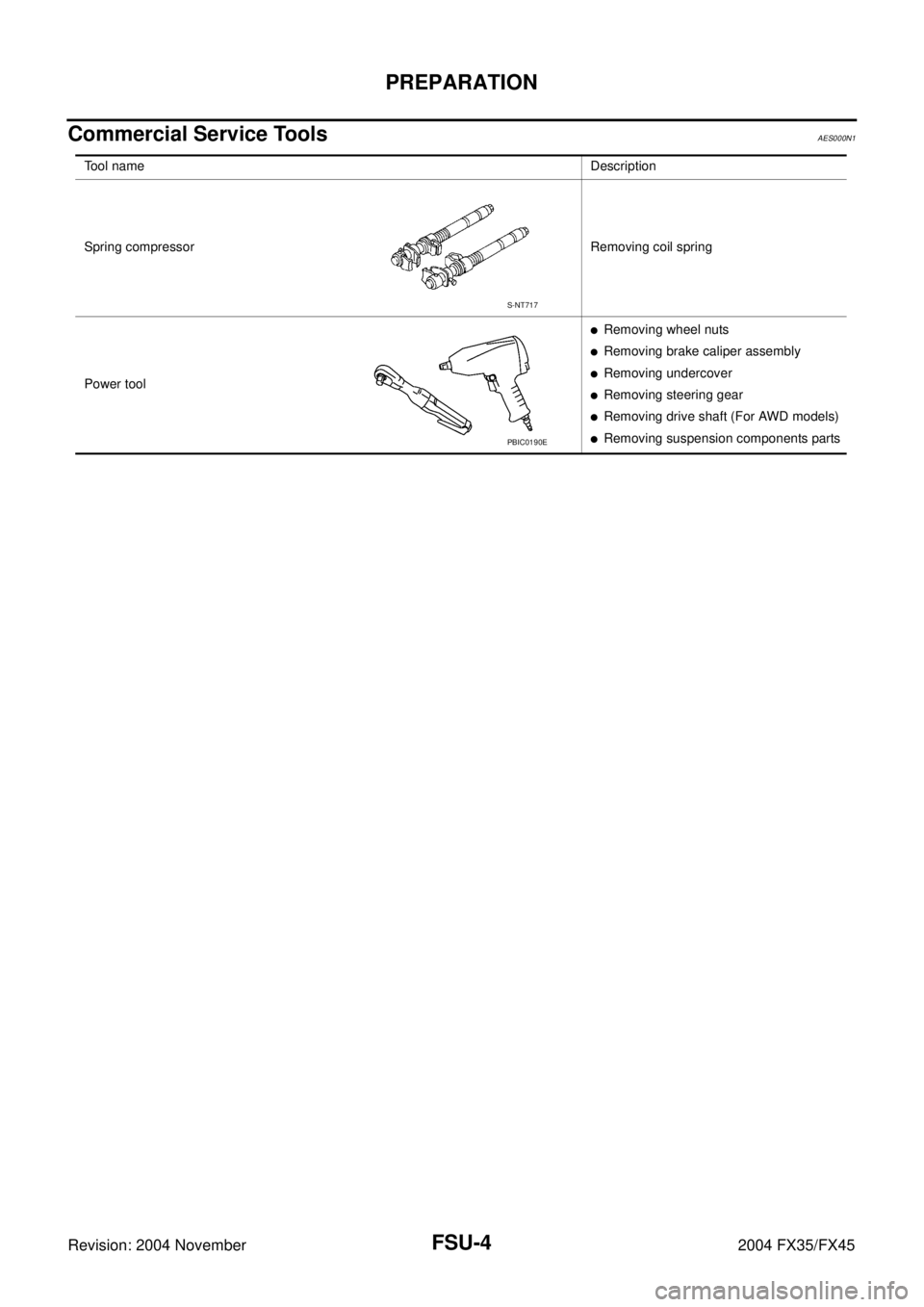
Commercial Service ToolsAES000N1
Tool nameDescription
Spring compressor Removing coil spring
Power tool
�Removing wheel nuts
�Removing brake caliper assembly
�Removing undercover
�Removing steering gear
�Removing drive shaft (For AWD models)
�Removing suspension components parts
S-NT717
PBIC0190E
Page 3090 of 4449
 TROUBLESHOOTING
FSU-5
C
D
F
G
H
I
J
K
L
MA
B
FSU
Revision: 2004 November 2004 FX35/FX45
NOISE, VIBRATION AND HARSHNESS (NVH) TROUBLESHOOTINGPFP:00003
NVH Troublesh")
NOISE, VIBRATION AND HARSHNESS (NVH) TROUBLESHOOTING
FSU-5
C
D
F
G
H
I
J
K
L
MA
B
FSU
Revision: 2004 November 2004 FX35/FX45
NOISE, VIBRATION AND HARSHNESS (NVH) TROUBLESHOOTINGPFP:00003
NVH Troubleshooting ChartAES000N2
Use chart below to help you find the cause of the symptom. If necessary, repair or replace these parts.
×: ApplicableReference page
FSU-8FSU-12
—
—
—
FSU-8FSU-6FSU-16
NVH in PR section
NVH in RFD section
NVH in RAX and RSU section
NVH in WT section
NVH in WT section
NVH in RAX section
NVH in BR section
NVH in PS section
Possible cause and SUSPECTED PARTS
Improper installation, looseness
Strut deformation, damage or deflection
Bushing or mounting deterioration
Parts interference
Spring fatigue
Suspension looseness
Incorrect wheel alignment
Stabilizer bar fatigue
PROPELLER SHAFT (For AWD models)
DIFFERENTIAL (For AWD models)
REAR AXLE AND REAR SUSPENSION
TIRES
ROAD WHEEL
DRIVE SHAFT (For AWD models)
BRAKES
STEERING
Symptom FRONT SUSPENSIONNoise××××× × ××× ×××××
Shake×××× × × × ×××××
Vibration××××× × ×× × ×
Shimmy×××× × ××× ××
Judder××× ××× ××
Poor quality ride or han-
dling××××× ×× ×××
Page 3091 of 4449

FSU-6
FRONT SUSPENSION ASSEMBLY
Revision: 2004 November 2004 FX35/FX45
FRONT SUSPENSION ASSEMBLYPFP:54010
On-Vehicle Inspection and ServiceAES000N3
Make sure the mounting conditions (looseness, back lash) of each component and component statues (wear,
damage) are normal.
INSPECTION OF TRANSVERSE LINK BALL JOINT END PLAY
1. Set front wheels in a straight-ahead position. Do not depress brake pedal.
2. Measure axial end play by installing and moving up/down between transverse link and steering knuckle
with an iron pry bar or something similar.
CAUTION:
Be careful not to damage ball joint boot.
STRUT INSPECTION
Check strut for oil leakage, damage and replace if necessary. Refer to FSU-11, "COIL SPRING AND STRUT" .
Wheel Alignment InspectionAES000N4
DESCRIPTION
Measure wheel alignment under unladen conditions.
NOTE:
Unladen conditions mean that fuel, engine coolant, and lubricant are full. Spare tire, jack, hand tools and mats
are designated positions.
PRELIMINARY CHECK
1. Check tires for improper air pressure and wear.
2. Check road wheels for runout.
3. Check wheel bearing axial end play.
4. Check transverse link ball joint axial end play.
5. Check strut operation.
6. Check each mounting part of axle and suspension for looseness and deformation.
7. Check each link, rod and member for cracks, deformation and other damage.
8. Check vehicle posture.
INSPECTION OF CAMBER, CASTER AND KINGPIN INCLINATION ANGLES
�Camber, caster, kingpin inclination angles cannot be adjusted.
�Before inspection, mount front wheels onto turning radius gauge. Mount rear wheels onto a stand that has
same height so vehicle will remain horizontal.
Using a CCK Gauge
Install CCK gauge attachment (SST: KV991040S0) as following procedure in wheel, then measure wheel
alignment.
1. Remove wheel nuts (3), and install a guide bolt to hub bolt.
2. Screw adapter into plate body until it contacts body tightly.
3. Screw center plate into plate.
4. Insert plate on guide bolt. Put spring in, and then evenly screw
both guide bolt nut. When fastening guide bolt nut, do not com-
pletely compress spring.Axial end play : 0 mm (0 in)
SEIA0240E
 TROUBLESHOOTING
Revision: 2004 November 2004 FX35/FX45
NOISE, VIBRATION AND HARSHNESS (NVH) TROUBLESHOOTINGPFP:00003
NVH Troubleshooting ChartADS000N6
Use th")