Page 472 of 4449
TROUBLE DIAGNOSIS
ATC-43
C
D
E
F
G
H
I
K
L
MA
B
AT C
Revision: 2004 November 2004 FX35/FX45
Component Parts and Harness Connector LocationAJS0014L
ENGINE COMPARTMENT
RJIA1963E
Page 482 of 4449
TROUBLE DIAGNOSIS
ATC-53
C
D
E
F
G
H
I
K
L
MA
B
AT C
Revision: 2004 November 2004 FX35/FX45
Self-diagnosis FunctionAJS0014P
DESCRIPTION
The self-diagnostic system diagnoses sensors, door motors, blower motor, etc. by system line. Refer to appli-
cable sections (items) for details. Shifting from usual control to the self-diagnostic system is accomplished by
starting the engine (turning the ignition switch ON) and pressing OFF switch for at least 5 seconds. The OFF
switch must be pressed within 10 seconds after starting the engine (ignition switch is turned ON). This system
will be canceled by either pressing AUTO switch or turning the ignition switch OFF. Shifting from one step to
another is accomplished by means of pressing temperature switch (driver side), as required.
Additionally shifting from STEP-5 to AUXILIARY MECHANISM is accomplished by means of pressing (fan)
UP switch.
RJIA1967E
Page 483 of 4449

ATC-54
TROUBLE DIAGNOSIS
Revision: 2004 November 2004 FX35/FX45
FUNCTION CONFIRMATION PROCEDURE
1. SET IN SELF-DIAGNOSTIC MODE
1. Turn ignition switch ON.
2. Set in self-diagnostic mode as follows. Within 10 seconds after starting engine (ignition switch is turned
ON.), press OFF switch for at least 5 seconds.
CAUTION:
�If battery voltage drops below 12V during diagnosis STEP-3, actuator speed becomes slower and
as a result, the system may generate an error even when operation is usual. To avoid this, start
engine before performing this diagnosis.
�Former STEP-1 (LEDs and display screen are checked) does not exist in this self-diagnosis func-
tion.
>> GO TO 2.
2. STEP-2: SENSOR CIRCUITS ARE CHECKED FOR OPEN OR SHORT CIRCUIT
Does code No. 20 appear on the display?
YES >> GO TO 3.
NO >> GO TO 13.
3. CHECK TO ADVANCE SELF-DIAGNOSIS STEP-3
Press temperature (UP) switch (driver side).
Advance to self
-diagnosis STEP-3?
YES >> GO TO 4.
NO >> Malfunctioning OFF switch or unified meter and A/C amp. Refer to ATC-102, "
Self-diagnosis" .
4. CHECK TO RETURN SELF-DIAGNOSIS STEP-2
Press temperature (DOWN) switch (driver side).
Return to self
-diagnosis STEP-2?
YES >> GO TO 5.
NO >> Replace A/C and AV switch. Temperature switch malfunctions.
5. STEP-3: MODE DOOR AND INTAKE DOOR POSITIONS ARE CHECKED
Press temperature (UP) switch (driver side).
Does code No. 30 appear on the display?
YES >> GO TO 6.
NO >> GO TO 14.
RJIA0219E
RJIA0220E
Page 490 of 4449

TROUBLE DIAGNOSIS
ATC-61
C
D
E
F
G
H
I
K
L
MA
B
AT C
Revision: 2004 November 2004 FX35/FX45
Operational CheckAJS0014Q
The purpose of the operational check is to confirm that the system operates properly.
CHECKING MEMORY FUNCTION
1. Set the temperature to 32°C (90°F).
2. Press OFF switch.
3. Turn ignition switch OFF.
4. Turn ignition switch ON.
5. Press the AUTO switch.
6. Confirm that the set temperature remains at previous tempera-
ture.
7. Press OFF switch.
If NG, go to trouble diagnosis procedure for ATC-103, "
Memory
Function" .
If OK, continue the check.
CHECKING BLOWER
1. Press fan (UP) switch. Blower should operate on low speed. The
fan symbol should have one blade lit.
2. Press fan (UP) switch again, and continue checking blower
speed and fan symbol until all speeds are checked.
3. Leave blower on MAX. speed.
If NG, go to trouble diagnosis procedure for AT C - 7 9 , "
Blower Motor
Circuit" .
If OK, continue the check.
CHECKING DISCHARGE AIR
1. Press MODE switch and DEF switch.
2. Each position indicator should change shape.
3. Confirm that discharge air comes out according to the air distri-
bution table. Refer to AT C - 3 7 , "
Discharge Air Flow" .
If NG, go to trouble diagnosis procedure for AT C - 7 0 , "
Mode Door
Motor Circuit" .
If OK, continue the check.
NOTE:
Confirm that the compressor clutch is engaged (sound or visual
inspection) and intake door position is at FRESH when the DEF
or D/F is selected.Conditions : Engine running at usual operating temperature
RJIA1972E
RJIA1973E
RJIA1974E
SJIA0302E
Page 510 of 4449

TROUBLE DIAGNOSIS
ATC-81
C
D
E
F
G
H
I
K
L
MA
B
AT C
Revision: 2004 November 2004 FX35/FX45
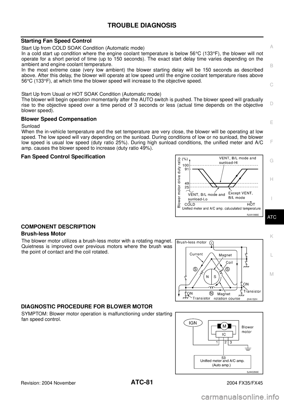
Starting Fan Speed Control
Start Up from COLD SOAK Condition (Automatic mode)
In a cold start up condition where the engine coolant temperature is below 56°C (133°F), the blower will not
operate for a short period of time (up to 150 seconds). The exact start delay time varies depending on the
ambient and engine coolant temperature.
In the most extreme case (very low ambient) the blower starting delay will be 150 seconds as described
above. After this delay, the blower will operate at low speed until the engine coolant temperature rises above
56°C (133°F), at which time the blower speed will increase to the objective speed.
Start Up from Usual or HOT SOAK Condition (Automatic mode)
The blower will begin operation momentarily after the AUTO switch is pushed. The blower speed will gradually
rise to the objective speed over a time period of 3 seconds or less (actual time depends on the objective
blower speed).
Blower Speed Compensation
Sunload
When the in-vehicle temperature and the set temperature are very close, the blower will be operating at low
speed. The low speed will vary depending on the sunload. During conditions of low or no sunload, the blower
low speed is usual low speed (duty ratio 25%). During high sunload conditions, the unified meter and A/C
amp. causes the blower speed to increase (duty ratio 49%).
Fan Speed Control Specification
COMPONENT DESCRIPTION
Brush-less Motor
The blower motor utilizes a brush-less motor with a rotating magnet.
Quietness is improved over previous motors where the brush was
the point of contact and the coil rotated.
DIAGNOSTIC PROCEDURE FOR BLOWER MOTOR
SYMPTOM: Blower motor operation is malfunctioning under starting
fan speed control.
RJIA1996E
ZHA152H
SJIA0266E
Page 517 of 4449

ATC-88
TROUBLE DIAGNOSIS
Revision: 2004 November 2004 FX35/FX45
8. CHECK REFRIGERANT PRESSURE SENSOR
WITH CONSULT-II
1. Start the engine.
2. Check voltage of refrigerant pressure sensor. Refer to EC-125, "
CONSULT-II Reference Value in Data
Monitor" (VQ35DE) or EC-775, "CONSULT-II Reference Value in Data Monitor" (VK45DE).
WITHOUT CONSULT-II
1. Start the engine.
2. Check voltage between ECM harness connector F101 terminal
70 (L/R) and ground.
OK or NG
OK >>�WITH CONSULT-II
GO TO 9.
�WITHOUT CONSULT-II
GO TO 10.
NG >> Refer to EC-609, "
REFRIGERANT PRESSURE SENSOR" (VQ35DE) or EC-1287, "REFRIGER-
ANT PRESSURE SENSOR" (VK45DE).
9. CHECK BCM INPUT (FAN ON) SIGNAL
Check FAN ON/OFF signal. Refer to AT C - 4 0 , "
CONSULT-II" .
OK or NG
OK >> GO TO 12.
NG >> GO TO 10.
10. CHECK CIRCUIT CONTINUITY BETWEEN BCM AND UNIFIED METER AND A/C AMP.
1. Turn ignition switch OFF.
2. Disconnect BCM connector and unified meter and A/C amp.
connector.
3. Check continuity between BCM harness connector M3 terminal
28 (BR/Y) and unified meter and A/C amp. harness connector
M57 terminal 57 (BR/Y).
OK or NG
OK >> GO TO 11.
NG >> Repair harness or connector.
Te r m i n a l s
Condition Voltage (+)
(−)
ECM con-
nectorTerminal No.
(wire color)
F101 70 (L/R) Ground A/C switch: ON Approx. 1 - 4V
PBIB1188E
FAN SW ON :FAN ON SIG ON
FAN SW OFF :FAN ON SIG OFF
R J I A 1111 E
28 – 57 : Continuity should exist.
RJIA2009E
Page 524 of 4449

TROUBLE DIAGNOSIS
ATC-95
C
D
E
F
G
H
I
K
L
MA
B
AT C
Revision: 2004 November 2004 FX35/FX45
PERFORMANCE CHART
Test Condition
Testing must be performed as follows:
Test Reading
Recirculating-to-discharge Air Temperature Table
Ambient Air Temperature-to-operating Pressure Table
Vehicle location Indoors or in the shade (in a well-ventilated place)
Doors Closed
Door window Open
Hood Open
TEMP. Max. COLD
Mode switch
(Ventilation) set
Recirculation (REC) switch
(Recirculation) set
Fan (blower) speedMax. speed set
Engine speed Idle speed
Operate the air conditioning system for 10 minutes before taking measurements.
Inside air (Recirculating air) at blower assembly inlet
Discharge air temperature at center ventilator
°C (°F) Relative humidity
%Air temperature
°C (°F)
50 - 6020 (68) 11.2 - 13.2 (52 - 56)
25 (77) 12.2 - 14.8 (54 - 59)
30 (86) 15.5 - 18.6 (60 - 65)
35 (95) 21.0 - 24.5 (70 - 76)
40 (104) 28.7 - 32.6 (84 - 91)
60 - 7020 (68) 13.2 - 15.2 (56 - 59)
25 (77) 14.8 - 17.3 (59 - 63)
30 (86) 18.6 - 21.6 (65 - 71)
35 (95) 24.5 - 28.0 (76 - 82)
40 (104) 32.6 - 36.5 (91 - 98)
Ambient air
High-pressure (Discharge side)
kPa (kg/cm
2 , psi)Low-pressure (Suction side)
kPa (kg/cm2 , psi) Relative humidity
%Air temperature
°C (°F)
50 - 7020 (68)961 - 1,167
(9.8 - 11.9, 139 - 169)216 - 265
(2.2 - 2.7, 31 - 38)
25 (77)1,108 - 1,353
(11.3 - 13.8, 161 - 196)230 - 281
(2.3 - 2.9, 33 - 41)
30 (86)1,275 - 1,549
(13.0 - 15.8, 185 - 225)261 - 320
(2.7 - 3.3, 38 - 46)
35 (95)1,549 - 1,893
(15.8 - 19.3, 225 - 274)297 - 364
(3.0 - 3.7, 43 - 53)
40 (104)1,814 - 2,216
(18.5 - 22.6, 263 - 321)357 - 435
(3.6 - 4.4, 52 - 63)
Page 525 of 4449

ATC-96
TROUBLE DIAGNOSIS
Revision: 2004 November 2004 FX35/FX45
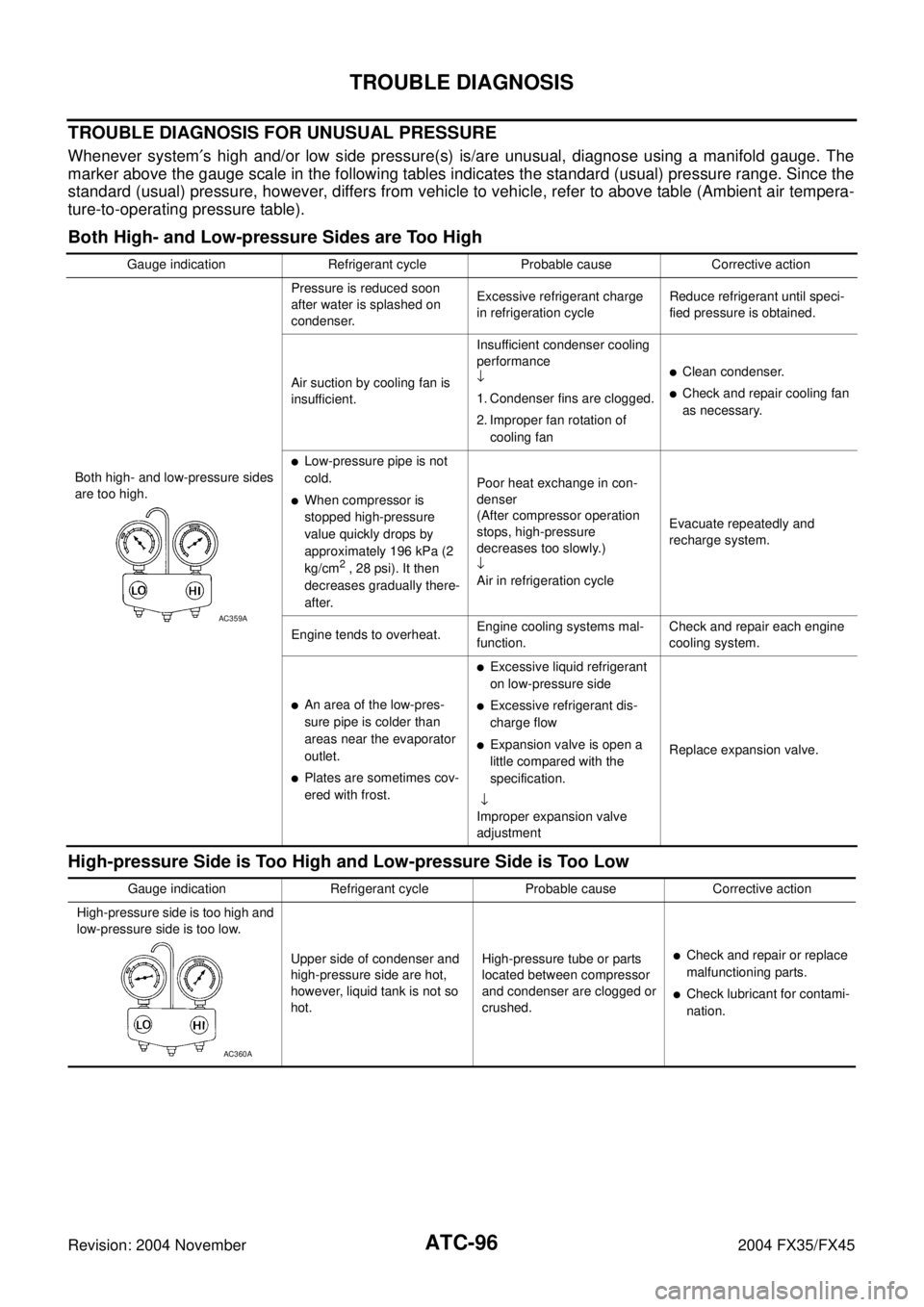
TROUBLE DIAGNOSIS FOR UNUSUAL PRESSURE
Whenever system′s high and/or low side pressure(s) is/are unusual, diagnose using a manifold gauge. The
marker above the gauge scale in the following tables indicates the standard (usual) pressure range. Since the
standard (usual) pressure, however, differs from vehicle to vehicle, refer to above table (Ambient air tempera-
ture-to-operating pressure table).
Both High- and Low-pressure Sides are Too High
High-pressure Side is Too High and Low-pressure Side is Too Low
Gauge indication Refrigerant cycle Probable cause Corrective action
Both high- and low-pressure sides
are too high.Pressure is reduced soon
after water is splashed on
condenser.Excessive refrigerant charge
in refrigeration cycleReduce refrigerant until speci-
fied pressure is obtained.
Air suction by cooling fan is
insufficient.Insufficient condenser cooling
performance
↓
1. Condenser fins are clogged.
2. Improper fan rotation of
cooling fan
�Clean condenser.
�Check and repair cooling fan
as necessary.
�Low-pressure pipe is not
cold.
�When compressor is
stopped high-pressure
value quickly drops by
approximately 196 kPa (2
kg/cm
2 , 28 psi). It then
decreases gradually there-
after.Poor heat exchange in con-
denser
(After compressor operation
stops, high-pressure
decreases too slowly.)
↓
Air in refrigeration cycleEvacuate repeatedly and
recharge system.
Engine tends to overheat.Engine cooling systems mal-
function.Check and repair each engine
cooling system.
�An area of the low-pres-
sure pipe is colder than
areas near the evaporator
outlet.
�Plates are sometimes cov-
ered with frost.
�Excessive liquid refrigerant
on low-pressure side
�Excessive refrigerant dis-
charge flow
�Expansion valve is open a
little compared with the
specification.
↓
Improper expansion valve
adjustmentReplace expansion valve.
AC359A
Gauge indication Refrigerant cycle Probable cause Corrective action
High-pressure side is too high and
low-pressure side is too low.
Upper side of condenser and
high-pressure side are hot,
however, liquid tank is not so
hot.High-pressure tube or parts
located between compressor
and condenser are clogged or
crushed.
�Check and repair or replace
malfunctioning parts.
�Check lubricant for contami-
nation.
AC360A