2004 INFINITI FX35 height
[x] Cancel search: heightPage 808 of 4449

BL-1
BODY, LOCK & SECURITY SYSTEM
I BODY
CONTENTS
C
D
E
F
G
H
J
K
L
M
SECTION BL
A
B
BL
Revision: 2004 November 2004 FX35/FX45
BODY, LOCK & SECURITY SYSTEM
PRECAUTIONS .......................................................... 5
Precautions for Supplemental Restraint System
(SRS) “AIR BAG” and “SEAT BELT PRE-TEN-
SIONER” .................................................................. 5
Precautions Necessary for Steering Wheel Rotation
After Battery Disconnect .......................................... 5
OPERATION PROCEDURE ................................. 5
Precautions for Work ................................................ 5
Wiring Diagnosis and Trouble Diagnosis ................. 6
PREPARATION ........................................................... 7
Special Service Tools ............................................... 7
Commercial Service Tools ........................................ 7
SQUEAK AND RATTLE TROUBLE DIAGNOSIS ...... 8
Work Flow ................................................................ 8
CUSTOMER INTERVIEW ..................................... 8
DUPLICATE THE NOISE AND TEST DRIVE ....... 9
CHECK RELATED SERVICE BULLETINS ........... 9
LOCATE THE NOISE AND IDENTIFY THE
ROOT CAUSE ...................................................... 9
REPAIR THE CAUSE ........................................... 9
CONFIRM THE REPAIR ..................................... 10
Generic Squeak and Rattle Troubleshooting ......... 10
INSTRUMENT PANEL ........................................ 10
CENTER CONSOLE ........................................... 10
DOORS ............................................................... 10
TRUNK ................................................................. 11
SUNROOF/HEADLINING .................................... 11
SEATS .................................................................. 11
UNDERHOOD ...................................................... 11
Diagnostic Worksheet ............................................ 12
HOOD ....................................................................... 14
Fitting Adjustment .................................................. 14
LONGITUDINAL AND LATERAL CLEARANCE
ADJUSTMENT .................................................... 14
FRONT END HEIGHT ADJUSTMENT ............... 14
SURFACE HEIGHT ADJUSTMENT ................... 14
Removal and Installation of Hood Assembly .......... 15
REMOVAL ........................................................... 16
INSTALLATION ................................................... 16
Removal and Installation of Hood Lock Control ..... 16REMOVAL ........................................................... 16
INSTALLATION ................................................... 17
Hood Lock Control Inspection ................................ 17
RADIATOR CORE SUPPORT .................................. 19
Removal and Installation ........................................ 19
REMOVAL ........................................................... 19
INSTALLATION ................................................... 20
FRONT FENDER ...................................................... 21
Removal and Installation ........................................ 21
REMOVAL ........................................................... 21
INSTALLATION ................................................... 21
POWER DOOR LOCK SYSTEM .............................. 22
Component Parts and Harness Connector Location ... 22
Component Parts and Harness Connector Location ... 23
System Description ................................................. 23
OUTLINE ............................................................. 24
CAN Communication System Description .............. 25
CAN Communication Unit ....................................... 25
Schematic (With Intelligent Key) ............................. 26
Wiring Diagram -D/LOCK- (With Intelligent Key) .... 27
FIG. 1 ................................................................... 27
FIG. 2 ................................................................... 28
FIG. 3 ................................................................... 29
FIG. 4 ................................................................... 30
FIG. 5 ................................................................... 31
Schematic (Without Intelligent Key) ........................ 32
Wiring Diagram -D/LOCK- (Without Intelligent Key) ... 33
FIG. 6 ................................................................... 33
FIG. 7 ................................................................... 34
FIG. 8 ................................................................... 35
FIG. 9 ................................................................... 36
Terminals and Reference Value for BCM ............... 37
Terminals and Reference Value for Intelligent Key
Unit (With Intelligent Key System) .......................... 37
Work Flow ............................................................... 37
Preliminary Check .................................................. 38
FUSE AND FUSIBLE LINK CHECK .................... 38
CONSULT-II Function ............................................. 39
CONSULT-II INSPECTION PROCEDURE .......... 39
CONSULT-II APPLICATION ITEMS .................... 40
Page 821 of 4449
BL-14
HOOD
Revision: 2004 November 2004 FX35/FX45
HOODPFP:F5100
Fitting AdjustmentAIS0051E
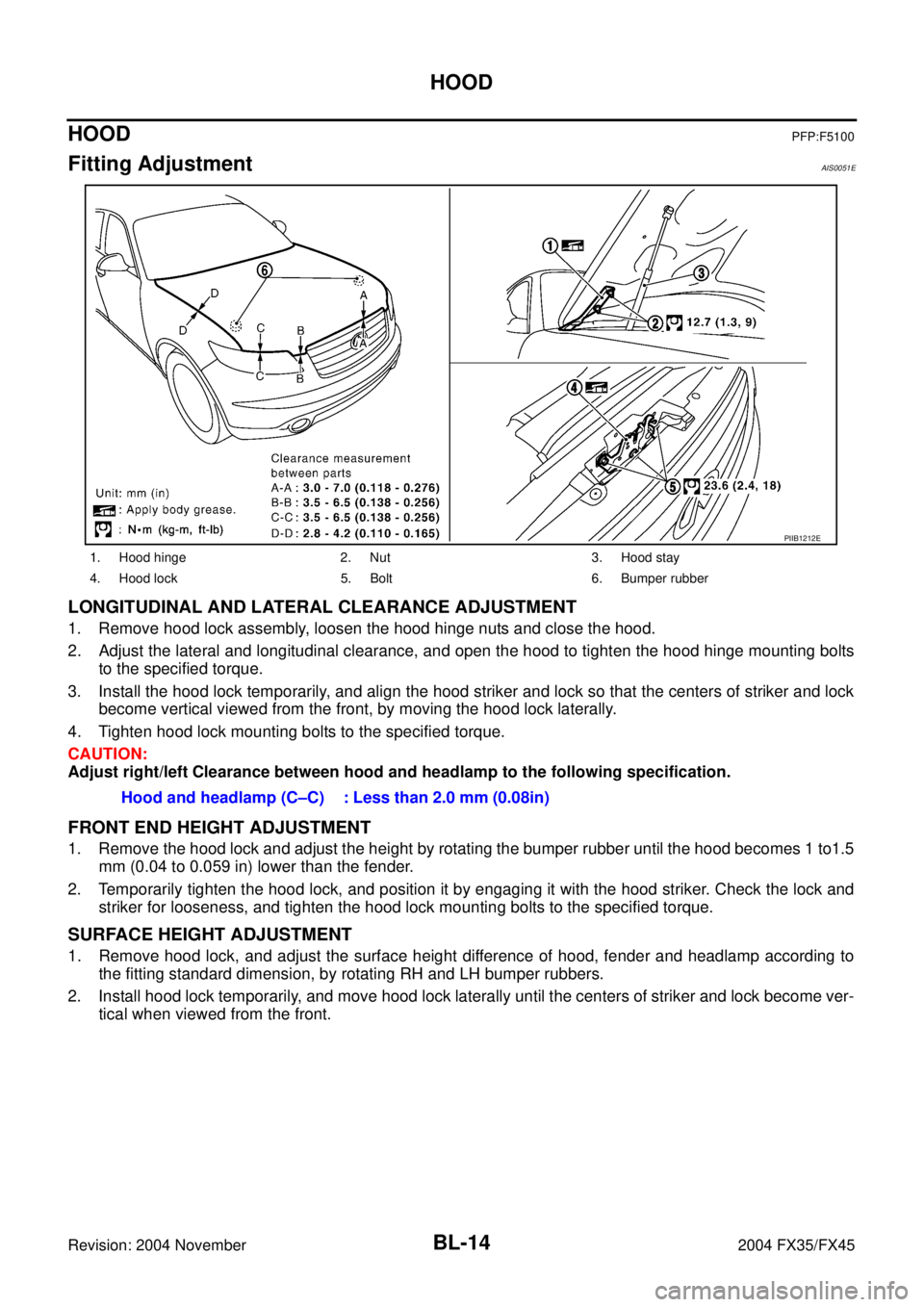
LONGITUDINAL AND LATERAL CLEARANCE ADJUSTMENT
1. Remove hood lock assembly, loosen the hood hinge nuts and close the hood.
2. Adjust the lateral and longitudinal clearance, and open the hood to tighten the hood hinge mounting bolts
to the specified torque.
3. Install the hood lock temporarily, and align the hood striker and lock so that the centers of striker and lock
become vertical viewed from the front, by moving the hood lock laterally.
4. Tighten hood lock mounting bolts to the specified torque.
CAUTION:
Adjust right/left Clearance between hood and headlamp to the following specification.
FRONT END HEIGHT ADJUSTMENT
1. Remove the hood lock and adjust the height by rotating the bumper rubber until the hood becomes 1 to1.5
mm (0.04 to 0.059 in) lower than the fender.
2. Temporarily tighten the hood lock, and position it by engaging it with the hood striker. Check the lock and
striker for looseness, and tighten the hood lock mounting bolts to the specified torque.
SURFACE HEIGHT ADJUSTMENT
1. Remove hood lock, and adjust the surface height difference of hood, fender and headlamp according to
the fitting standard dimension, by rotating RH and LH bumper rubbers.
2. Install hood lock temporarily, and move hood lock laterally until the centers of striker and lock become ver-
tical when viewed from the front.
1. Hood hinge 2. Nut 3. Hood stay
4. Hood lock 5. Bolt 6. Bumper rubber
PIIB1212E
Hood and headlamp (C–C) : Less than 2.0 mm (0.08in)
Page 822 of 4449
HOOD
BL-15
C
D
E
F
G
H
J
K
L
MA
B
BL
Revision: 2004 November 2004 FX35/FX45
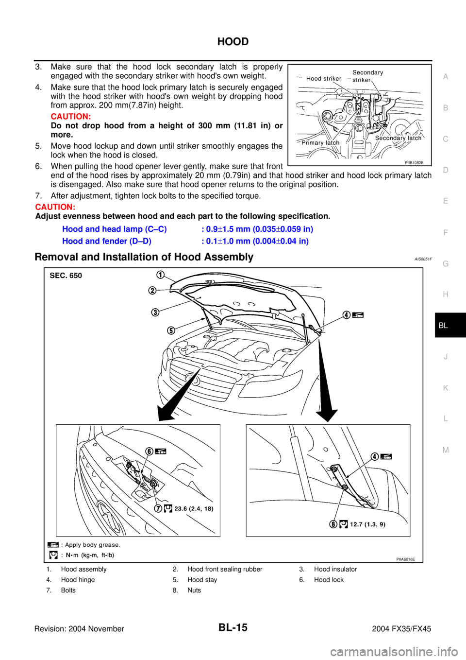
3. Make sure that the hood lock secondary latch is properly
engaged with the secondary striker with hood's own weight.
4. Make sure that the hood lock primary latch is securely engaged
with the hood striker with hood's own weight by dropping hood
from approx. 200 mm(7.87in) height.
CAUTION:
Do not drop hood from a height of 300 mm (11.81 in) or
more.
5. Move hood lockup and down until striker smoothly engages the
lock when the hood is closed.
6. When pulling the hood opener lever gently, make sure that front
end of the hood rises by approximately 20 mm (0.79in) and that hood striker and hood lock primary latch
is disengaged. Also make sure that hood opener returns to the original position.
7. After adjustment, tighten lock bolts to the specified torque.
CAUTION:
Adjust evenness between hood and each part to the following specification.
Removal and Installation of Hood AssemblyAIS0051F
Hood and head lamp (C–C) : 0.9±1.5 mm (0.035±0.059 in)
Hood and fender (D–D) : 0.1±1.0 mm (0.004±0.04 in)
PIIB1082E
1. Hood assembly 2. Hood front sealing rubber 3. Hood insulator
4. Hood hinge 5. Hood stay 6. Hood lock
7. Bolts 8. Nuts
PIIA6016E
Page 824 of 4449
HOOD
BL-17
C
D
E
F
G
H
J
K
L
MA
B
BL
Revision: 2004 November 2004 FX35/FX45
4. Remove instrument driver lower panel. Refer to IP-11, "Removal and Installation" .
5. After the bolt of the case with the air cleaner is disconnected, and it is moved, the cable is pulled.
6. Remove the grommet on the dashboard, and pull the hood lock cable toward the passenger room.
CAUTION:
While pulling, be careful not to damage (peeling) the outside of the hood lock cable.
INSTALLATION
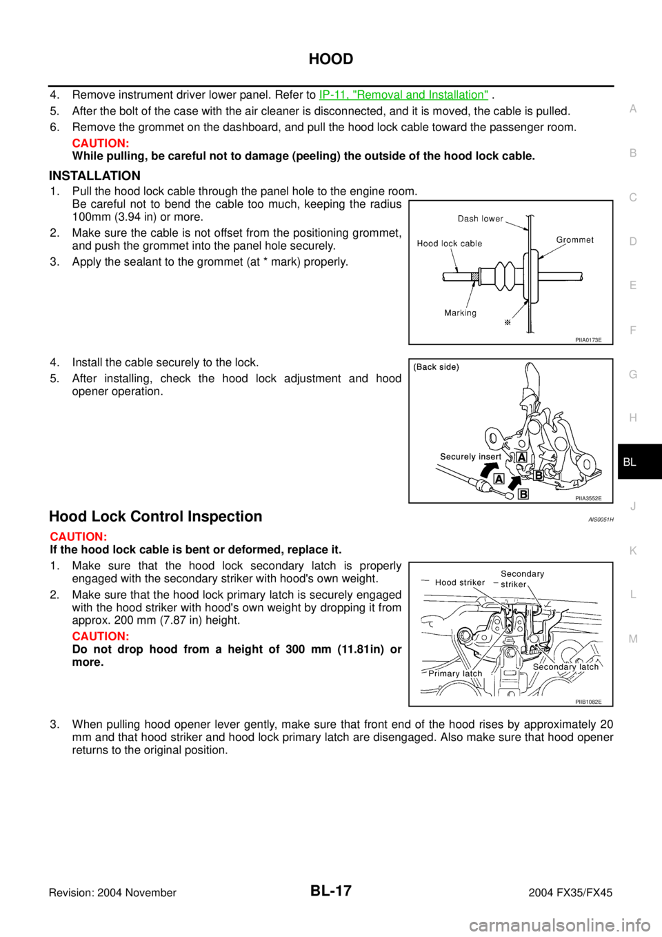
1. Pull the hood lock cable through the panel hole to the engine room.
Be careful not to bend the cable too much, keeping the radius
100mm (3.94 in) or more.
2. Make sure the cable is not offset from the positioning grommet,
and push the grommet into the panel hole securely.
3. Apply the sealant to the grommet (at * mark) properly.
4. Install the cable securely to the lock.
5. After installing, check the hood lock adjustment and hood
opener operation.
Hood Lock Control InspectionAIS0051H
CAUTION:
If the hood lock cable is bent or deformed, replace it.
1. Make sure that the hood lock secondary latch is properly
engaged with the secondary striker with hood's own weight.
2. Make sure that the hood lock primary latch is securely engaged
with the hood striker with hood's own weight by dropping it from
approx. 200 mm (7.87 in) height.
CAUTION:
Do not drop hood from a height of 300 mm (11.81in) or
more.
3. When pulling hood opener lever gently, make sure that front end of the hood rises by approximately 20
mm and that hood striker and hood lock primary latch are disengaged. Also make sure that hood opener
returns to the original position.
PIIA0173E
PIIA3552E
PIIB1082E
Page 955 of 4449
BL-148
DOOR
Revision: 2004 November 2004 FX35/FX45
DOORPFP:80100
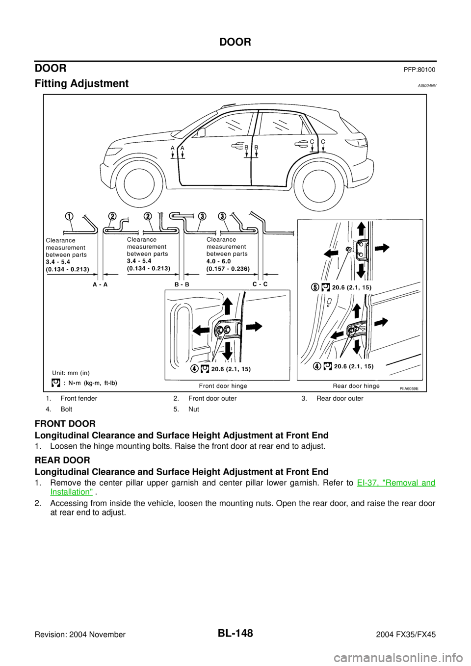
Fitting AdjustmentAIS004NV
FRONT DOOR
Longitudinal Clearance and Surface Height Adjustment at Front End
1. Loosen the hinge mounting bolts. Raise the front door at rear end to adjust.
REAR DOOR
Longitudinal Clearance and Surface Height Adjustment at Front End
1. Remove the center pillar upper garnish and center pillar lower garnish. Refer to EI-37, "Removal and
Installation" .
2. Accessing from inside the vehicle, loosen the mounting nuts. Open the rear door, and raise the rear door
at rear end to adjust.
1. Front fender 2. Front door outer 3. Rear door outer
4. Bolt 5. Nut
PIIA6059E
Page 966 of 4449

BACK DOOR
BL-159
C
D
E
F
G
H
J
K
L
MA
B
BL
Revision: 2004 November 2004 FX35/FX45
BACK DOORPFP:90100
Fitting AdjustmentAIS004O4
VERTICAL/LATERAL CLEARANCE ADJUSTMENT
1. With the striker released, loosen the bumper rubber lock nuts.
2. Close the back door lightly and adjust the surface height by rotating the bumper rubber and, then open the
back door to finally tighten the back door lock mounting bolts and bumper rubber lock nuts to the specified
torque.
Back Door AssemblyAIS004O5
REMOVAL
1. Remove roof rear garnish assembly. Refer to EI-44, "Removal and Installation" .
2. Disconnect the back door harness connector and AV antenna
feeder.
3. Washer hose is separated in the connection part.
4. Support the back door lock with a proper material to prevent it
from falling.
WARNING:
Body injury may occur if no supporting rod is holding the
back door open when removing the damper stay.
1. Bumper rubber 2. Back door striker 3. Screw
PIIB0208E
PIIA6028E
PIIA6061E
Page 1099 of 4449
BR-6
BRAKE PEDAL
Revision: 2004 November 2004 FX35/FX45
BRAKE PEDALPFP:46501
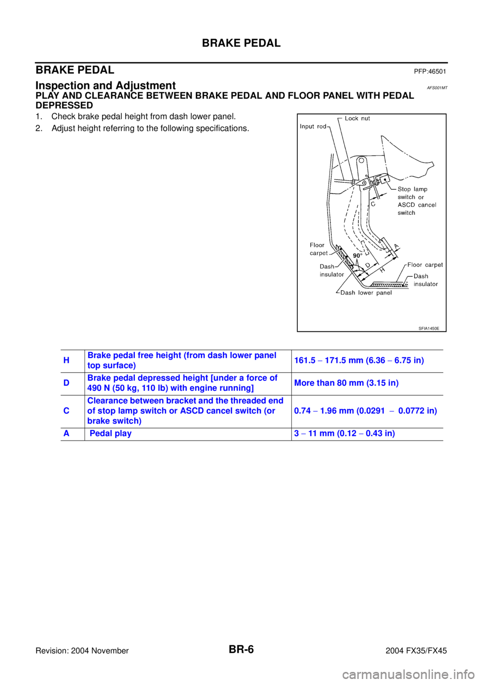
Inspection and AdjustmentAFS001MT
PLAY AND CLEARANCE BETWEEN BRAKE PEDAL AND FLOOR PANEL WITH PEDAL
DEPRESSED
1. Check brake pedal height from dash lower panel.
2. Adjust height referring to the following specifications.
SFIA1450E
HBrake pedal free height (from dash lower panel
top surface)161.5 − 171.5 mm (6.36 − 6.75 in)
DBrake pedal depressed height [under a force of
490 N (50 kg, 110 lb) with engine running]More than 80 mm (3.15 in)
CClearance between bracket and the threaded end
of stop lamp switch or ASCD cancel switch (or
brake switch)0.74 − 1.96 mm (0.0291−0.0772 in)
A Pedal play 3 − 11 mm (0.12 − 0.43 in)
Page 1100 of 4449
BRAKE PEDAL
BR-7
C
D
E
G
H
I
J
K
L
MA
B
BR
Revision: 2004 November 2004 FX35/FX45
ADJUSTMENT
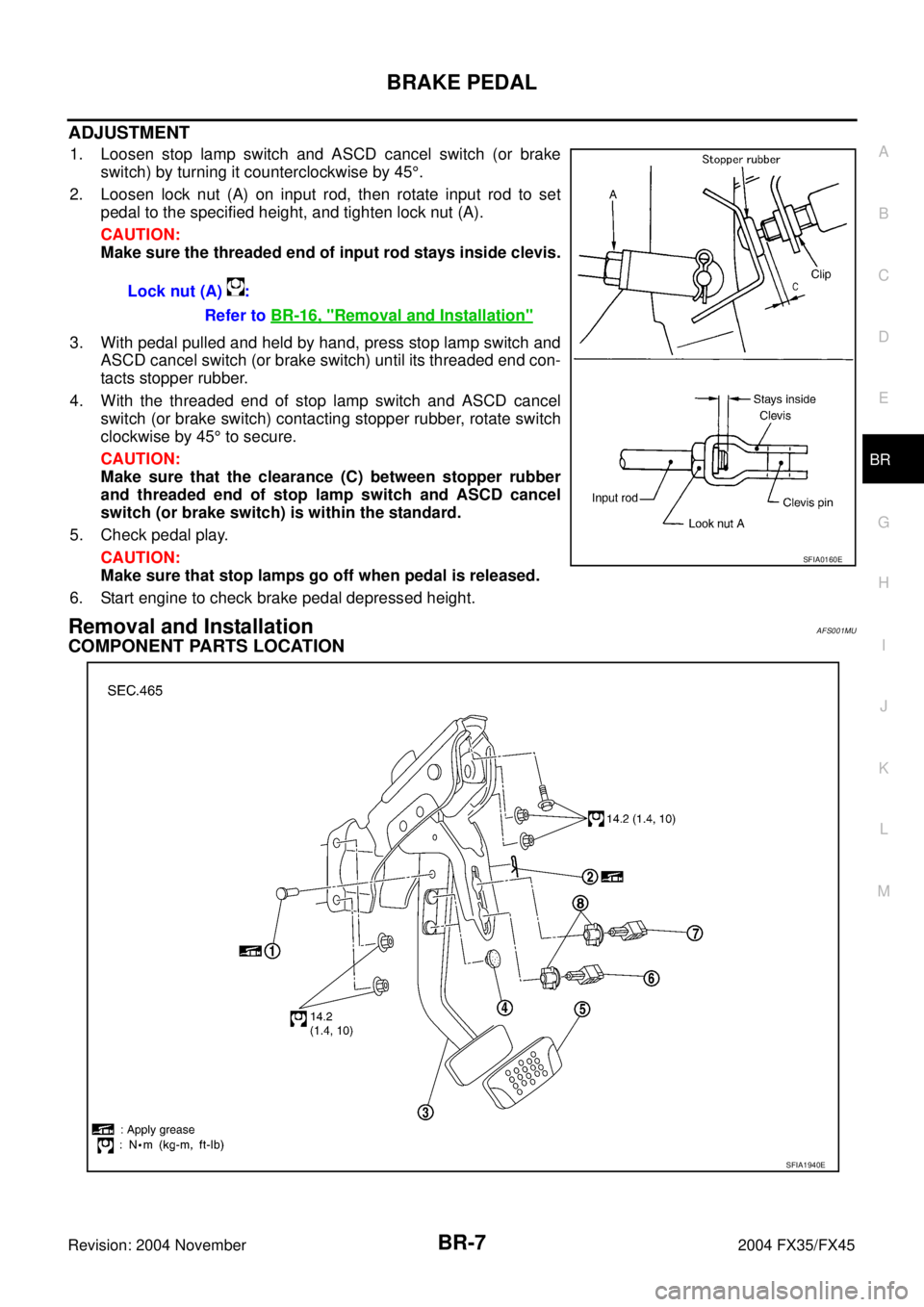
1. Loosen stop lamp switch and ASCD cancel switch (or brake
switch) by turning it counterclockwise by 45°.
2. Loosen lock nut (A) on input rod, then rotate input rod to set
pedal to the specified height, and tighten lock nut (A).
CAUTION:
Make sure the threaded end of input rod stays inside clevis.
3. With pedal pulled and held by hand, press stop lamp switch and
ASCD cancel switch (or brake switch) until its threaded end con-
tacts stopper rubber.
4. With the threaded end of stop lamp switch and ASCD cancel
switch (or brake switch) contacting stopper rubber, rotate switch
clockwise by 45° to secure.
CAUTION:
Make sure that the clearance (C) between stopper rubber
and threaded end of stop lamp switch and ASCD cancel
switch (or brake switch) is within the standard.
5. Check pedal play.
CAUTION:
Make sure that stop lamps go off when pedal is released.
6. Start engine to check brake pedal depressed height.
Removal and InstallationAFS001MU
COMPONENT PARTS LOCATION
Lock nut (A) :
Refer to BR-16, "
Removal and Installation"
SFIA0160E
SFIA1940E