Page 1101 of 4449
. EI-39, \"KICKING PLATE\" .
2. Remove dash side finisher (driver side). EI-38, \"
DASH SIDE FIN")
BR-8
BRAKE PEDAL
Revision: 2004 November 2004 FX35/FX45
REMOVAL
1. Remove front kicking plate (driver side). EI-39, "KICKING PLATE" .
2. Remove dash side finisher (driver side). EI-38, "
DASH SIDE FINISHER" .
3. Remove instrument lower panel (driver side). IP-19, "
INSTRUMENT PASSENGER LOWER PANEL" .
4. Remove steering column assembly. Refer to PS-12, "
Removal and Installation" .
5. Remove stop lamp switch and ASCD cancel switch (or brake switch) from pedal assembly.
6. Remove snap pin and clevis pin from brake booster clevis.
7. Remove mounting nuts and bolts from bracket, and remove
pedal assembly from the vehicle.
INSPECTION AFTER REMOVAL
�Check that the rivets in the upper part of brake pedal are not
deformed.
�Make sure sub bracket and slide plate are at least 4 mm (0.16
in) apart.
�Check brake pedal for bend, damage, and cracks on the welded
parts. Replace the applicable part if a failure is detected.
�Check clevis pin and resin stopper for damage and deformation.
If a failure is detected, replace clevis pin.
INSTALLATION
Paying attention to the following items, install in the reverse order of removal.
�After installing brake pedal assembly to the vehicle, adjust brake pedal height.
1. Clevis pin 2. Snap pin 3. Brake pedal assembly
4. Stopper rubber 5. Pedal pad 6. ASCD cancel switch (Models with
ASCD)
Brake switch (Models with ACC)
7. Stop lamp switch 8. Clip
SFIA0159E
PFIA0223E
SBR997
Page 1110 of 4449
BRAKE BOOSTER
BR-17
C
D
E
G
H
I
J
K
L
MA
B
BR
Revision: 2004 November 2004 FX35/FX45
INSTALLATION
1. Loosen lock nut to adjust input rod length so that the length B (in
the figure) satisfies the specified value.
2. After adjusting “B”, temporarily tighten lock nut to install booster
assembly to the vehicle. At this time, make sure to install a gas-
ket between booster assembly and the dash panel.
3. Connect brake pedal with clevis of input rod.
4. Install pedal bracket mounting nuts and tighten them to the
specified torque.
5. Install brake piping from brake master cylinder to ABS actuator.
Refer to BR-11, "
Hydraulic Circuit" .
6. Install master cylinder to booster assembly. Refer to BR-16, "
Removal and Installation" .
7. Adjust the height and play of brake pedal.
8. Tighten lock nut of input rod to the specified torque.
9. Refill new brake fluid and bleed air. Refer to BR-10, "
Bleeding Brake System" . Length “B” : 125 mm (4.92 in)
SGIA0060E
Page 1124 of 4449

BR-31
C
D
E
G
H
I
J
K
L
MA
B
BR
Revision: 2004 November 2004 FX35/FX45
SERVICE DATA AND SPECIFICATIONS (SDS)PFP:00030
General SpecificationsAFS001NF
Unit: mm (in)")
SERVICE DATA AND SPECIFICATIONS (SDS)
BR-31
C
D
E
G
H
I
J
K
L
MA
B
BR
Revision: 2004 November 2004 FX35/FX45
SERVICE DATA AND SPECIFICATIONS (SDS)PFP:00030
General SpecificationsAFS001NF
Unit: mm (in)
Brake PedalAFS001NG
Brake BoosterAFS001NH
Va c u u m t y p e
Check ValveAFS001NI
Front Disc BrakeAFS001NJ
Front brake Brake model CLZ31VC
Rotor outer diameter × thickness 320 × 28 (12.60 × 1.10)
Pad Length × width × thickness 111.0 × 73.5 × 9.5 (4.73 × 2.894 × 0.374)
Cylinder bore diameter 63.6 (2.504)
Rear brake Brake model AD14VE
Rotor outer diameter × thickness 308 × 16 (12.13 × 0.63)
Pad Length × width × thickness 83.0 × 33.0 × 8.5 (3.268 × 1.299 × 0.335)
Cylinder bore diameter 42.86 (1.6874)
Master cylinder Cylinder bore diameter 25.4 (1.00)
Control valve Valve model Electric brake force distribution
Brake booster Booster model C215T
Diaphragm diameterPrimary 228.5 (9.0)
Secondary 203.0 (8.0)
Recommended brake fluidDOT 3
Brake pedal height (from dash panel top surface) 161.5 − 171.5 mm (6.36 − 6.75 in)
Depressed pedal height [under a force of 490 N (50 kg, 110 lb)
with engine running]More than 80 mm (3.15 in)
Clearance between stopper rubber and the threaded end of
stop lamp switch 0.74 − 1.96 mm (0.0291 − 0.0772 in)
Pedal play 3 − 11 mm (0.12 − 0.43 in)
Input rod installation standard dimension 15.6 − 15.9 mm (0.614 − 0.626 in)
Vacuum leakage
[at vacuum of – 66.7 kPa(– 500 mmHg, – 19.69 inHg)]Within 1.3 kPa (10 mmHg, 0.39 inHg) of vacuum for 15 seconds
Brake modelCLZ31VC
Brake padStandard thickness (new) 9.5 mm (0.374 in)
Repair limit thickness 2.0 mm (0.079 in)
Disc rotorStandard thickness (new) 28.0 mm (1.102 in)
Repair limit thickness 26.0 mm (1.024 in)
Maximum uneven wear (measured at 8 positions) 0.015mm (0.0006 in)
Runout limit (with it attached to the vehicle) 0.04 mm (0.0016 in)
Page 1209 of 4449
CO-20
[VQ35DE]
RADIATOR (ALUMINUM TYPE)
Revision: 2004 November 2004 FX35/FX45
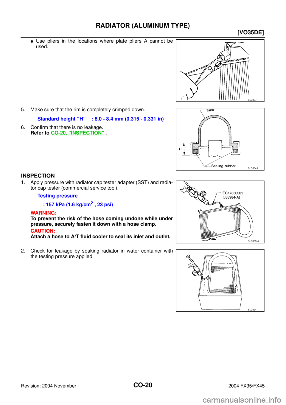
�Use pliers in the locations where plate pliers A cannot be
used.
5. Make sure that the rim is completely crimped down.
6. Confirm that there is no leakage.
Refer to CO-20, "
INSPECTION" .
INSPECTION
1. Apply pressure with radiator cap tester adapter (SST) and radia-
tor cap tester (commercial service tool).
WARNING:
To prevent the risk of the hose coming undone while under
pressure, securely fasten it down with a hose clamp.
CAUTION:
Attach a hose to A/T fluid cooler to seal its inlet and outlet.
2. Check for leakage by soaking radiator in water container with
the testing pressure applied.
SLC897
Standard height “H” : 8.0 - 8.4 mm (0.315 - 0.331 in)
SLC554A
Testing pressure
: 157 kPa (1.6 kg/cm
2 , 23 psi)
SLC933-A
SLC934
Page 1235 of 4449
![INFINITI FX35 2004 Service Manual CO-46
[VK45DE]
RADIATOR (ALUMINUM TYPE)
Revision: 2004 November 2004 FX35/FX45
�Use pliers in the locations where radiator plate pliers A cannot
be used.
5. Make sure that the rim is completely crimpe](/manual-img/42/57021/w960_57021-1234.png "INFINITI FX35 2004 Service Manual CO-46
[VK45DE]
RADIATOR (ALUMINUM TYPE)
Revision: 2004 November 2004 FX35/FX45
�Use pliers in the locations where radiator plate pliers A cannot
be used.
5. Make sure that the rim is completely crimpe")
CO-46
[VK45DE]
RADIATOR (ALUMINUM TYPE)
Revision: 2004 November 2004 FX35/FX45
�Use pliers in the locations where radiator plate pliers A cannot
be used.
5. Make sure that the rim is completely crimped down.
6. Make sure that there is no leakage.
Refer to CO-46, "
INSPECTION" .
INSPECTION
1. Apply pressure with radiator cap tester adapter (SST) and radia-
tor cap tester (commercial service tool).
�provide used radiator and connect it to tested radiator using
radiator hoses as shown in the figure.
NOTE:
The used radiator should be tested beforehand to confirm it
has no leakage. If used one is not available, it is possible to
use new service part as a radiator testing tool.
WARNING:
To prevent the risk of hose coming undone while under pressure, securely fasten it down with
hose clamp.
CAUTION:
Attach hose to A/T fluid cooler to seal its inlet and outlet.
2. Check for leakage by soaking radiator in water container with
the testing pressure applied.
SLC897
Standard height “H” : 8.0 - 8.4 mm (0.315 - 0.331 in)
SLC554A
Testing pressure
: 157 kPa (1.6 kg/cm
2 , 23 psi)PBIC1658E
PBIC1699E
Page 1497 of 4449
![INFINITI FX35 2004 Service Manual EC-156
[VQ35DE]
DTC P0031, P0032, P0051, P0052 HO2S1 HEATER
Revision: 2004 November 2004 FX35/FX45
5. CHECK HEATED OXYGEN SENSOR 1 HEATER
Refer to EC-156, "
Component Inspection" .
OK or NG
OK >> GO T](/manual-img/42/57021/w960_57021-1496.png "INFINITI FX35 2004 Service Manual EC-156
[VQ35DE]
DTC P0031, P0032, P0051, P0052 HO2S1 HEATER
Revision: 2004 November 2004 FX35/FX45
5. CHECK HEATED OXYGEN SENSOR 1 HEATER
Refer to EC-156, \"
Component Inspection\" .
OK or NG
OK >> GO T")
EC-156
[VQ35DE]
DTC P0031, P0032, P0051, P0052 HO2S1 HEATER
Revision: 2004 November 2004 FX35/FX45
5. CHECK HEATED OXYGEN SENSOR 1 HEATER
Refer to EC-156, "
Component Inspection" .
OK or NG
OK >> GO TO 6.
NG >> Replace malfunctioning heated oxygen sensor 1.
6. CHECK INTERMITTENT INCIDENT
Refer to EC-135, "
TROUBLE DIAGNOSIS FOR INTERMITTENT INCIDENT" .
>>INSPECTION END
Component InspectionABS006LP
HEATED OXYGEN SENSOR 1 HEATER
1. Check resistance between HO2S1 terminals as follows.
2. If NG, replace heated oxygen sensor 1.
CAUTION:
�Discard any heated oxygen sensor which has been dropped
from a height of more than 0.5 m (19.7 in) onto a hard sur-
face such as a concrete floor; use a new one.
�Before installing new oxygen sensor, clean exhaust system
threads using Oxygen Sensor Thread Cleaner tool J-43897-
18 or J-43897-12 and approved anti-seize lubricant.
Removal and InstallationABS006LQ
HEATED OXYGEN SENSOR 1
Refer to EM-26, "EXHAUST MANIFOLD AND THREE WAY CATALYST" .
Terminal No. Resistance
2 and 3 3.3 - 4.0 Ω at 25°C (77°F)
1 and 2, 3, 4
∞ Ω
(Continuity should not exist)
4 and 1, 2, 3
PBIB0970E
Page 1505 of 4449
![INFINITI FX35 2004 Service Manual EC-164
[VQ35DE]
DTC P0037, P0038, P0057, P0058 HO2S2 HEATER
Revision: 2004 November 2004 FX35/FX45
5. CHECK HEATED OXYGEN SENSOR 2 HEATER
Refer to EC-164, "
Component Inspection" .
OK or NG
OK >> GO T](/manual-img/42/57021/w960_57021-1504.png "INFINITI FX35 2004 Service Manual EC-164
[VQ35DE]
DTC P0037, P0038, P0057, P0058 HO2S2 HEATER
Revision: 2004 November 2004 FX35/FX45
5. CHECK HEATED OXYGEN SENSOR 2 HEATER
Refer to EC-164, \"
Component Inspection\" .
OK or NG
OK >> GO T")
EC-164
[VQ35DE]
DTC P0037, P0038, P0057, P0058 HO2S2 HEATER
Revision: 2004 November 2004 FX35/FX45
5. CHECK HEATED OXYGEN SENSOR 2 HEATER
Refer to EC-164, "
Component Inspection" .
OK or NG
OK >> GO TO 6.
NG >> Replace malfunctioning heated oxygen sensor 2.
6. CHECK INTERMITTENT INCIDENT
Refer to EC-135, "
TROUBLE DIAGNOSIS FOR INTERMITTENT INCIDENT" .
>>INSPECTION END
Component InspectionABS006LX
HEATED OXYGEN SENSOR 2 HEATER
1. Check resistance between HO2S2 terminals as follows.
2. If NG, replace heated oxygen sensor 2.
CAUTION:
�Discard any heated oxygen sensor which has been dropped
from a height of more than 0.5 m (19.7 in) onto a hard sur-
face such as a concrete floor; use a new one.
�Before installing new oxygen sensor, clean exhaust system
threads using Oxygen Sensor Thread Cleaner tool J-43897-
18 or J-43897-12 and approved anti-seize lubricant.
Removal and InstallationABS006LY
HEATED OXYGEN SENSOR 2
Refer to EM-26, "EXHAUST MANIFOLD AND THREE WAY CATALYST" .
Terminal No. Resistance
2 and 3 5.0 - 7.0 Ω at 25°C (77°F)
1 and 2, 3, 4
∞ Ω
(Continuity should not exist)
4 and 1, 2, 3
PBIB0970E
Page 1554 of 4449
![INFINITI FX35 2004 Service Manual DTC P0132, P0152 HO2S1
EC-213
[VQ35DE]
C
D
E
F
G
H
I
J
K
L
MA
EC
Revision: 2004 November 2004 FX35/FX45
CAUTION:
�Discard any heated oxygen sensor which has been dropped from a height of more than 0.5](/manual-img/42/57021/w960_57021-1553.png "INFINITI FX35 2004 Service Manual DTC P0132, P0152 HO2S1
EC-213
[VQ35DE]
C
D
E
F
G
H
I
J
K
L
MA
EC
Revision: 2004 November 2004 FX35/FX45
CAUTION:
�Discard any heated oxygen sensor which has been dropped from a height of more than 0.5")
DTC P0132, P0152 HO2S1
EC-213
[VQ35DE]
C
D
E
F
G
H
I
J
K
L
MA
EC
Revision: 2004 November 2004 FX35/FX45
CAUTION:
�Discard any heated oxygen sensor which has been dropped from a height of more than 0.5 m
(19.7 in) onto a hard surface such as a concrete floor; use a new one.
�Before installing new oxygen sensor, clean exhaust system threads using Oxygen Sensor
Thread Cleaner tool J-43897-18 or J-43897-12 and approved anti-seize lubricant.
Without CONSULT-II
1. Start engine and warm it up to normal operating temperature.
2. Set voltmeter probes between ECM terminal 35 [HO2S1 (B1) signal] or 16 [HO2S1 (B2) signal] and
ground.
3. Check the following with engine speed held at 2,000 rpm con-
stant under no load.
�The voltage fluctuates between 0 to 0.3V and 0.6 to 1.0V
more than 5 times within 10 seconds.
�The maximum voltage is over 0.6V at least one time.
�The minimum voltage is below 0.3V at least one time.
�The voltage never exceeds 1.0V.
1 time: 0 - 0.3V → 0.6 - 1.0V → 0 - 0.3V
2 times: 0 - 0.3V → 0.6 - 1.0V → 0 - 0.3V → 0.6 - 1.0V → 0 -
0.3V
CAUTION:
�Discard any heated oxygen sensor which has been dropped from a height of more than 0.5 m
(19.7 in) onto a hard surface such as a concrete floor; use a new one.
�Before installing new oxygen sensor, clean exhaust system threads using Oxygen Sensor
Thread Cleaner tool J-43897-18 or J-43897-12 and approved anti-seize lubricant.
Removal and InstallationABS006NY
HEATED OXYGEN SENSOR 1
Refer to EM-26, "EXHAUST MANIFOLD AND THREE WAY CATALYST" .
SEF648Y
PBIB1107E
 satisfies the speci")