Page 740 of 4449
NAVIGATION SYSTEM
AV-149
C
D
E
F
G
H
I
J
L
MA
B
AV
Revision: 2004 November 2004 FX35/FX45
Power Supply and Ground Circuit Check for A/C and AV SwitchAKS00BNA
1. CHECK FUSE
Make sure that the following fuses of the A/C and AV switch are not blown.
OK or NG
OK >> GO TO 2.
NG >> If fuse is blown, be sure to eliminate case of malfunction before installing new fuse. Refer to PG-3,
"POWER SUPPLY ROUTING CIRCUIT" .
2. CHECK POWER SUPPLY CIRCUIT
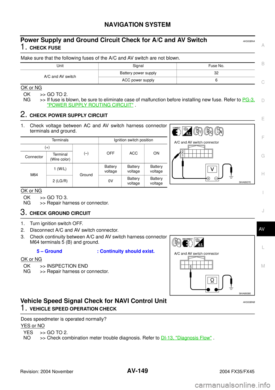
1. Check voltage between AC and AV switch harness connector
terminals and ground.
OK or NG
OK >> GO TO 3.
NG >> Repair harness or connector.
3. CHECK GROUND CIRCUIT
1. Turn ignition switch OFF.
2. Disconnect A/C and AV switch connector.
3. Check continuity between A/C and AV switch harness connector
M64 terminals 5 (B) and ground.
OK or NG
OK >> INSPECTION END
NG >> Repair harness or connector.
Vehicle Speed Signal Check for NAVI Control UnitAKS00BNB
1. VEHICLE SPEED OPERATION CHECK
Does speedmeter is operated normally?
YES or NO
YES >> GO TO 2.
NO >> Check combination meter trouble diagnosis. Refer to DI-13, "
Diagnosis Flow" .
Unit Signal Fuse No.
A/C and AV switchBattery power supply 32
ACC power supply 6
Terminals Ignition switch position
(+)
(–) OFF ACC ON
ConnectorTe r m i n a l
(Wire color)
M641 (W/L)
GroundBattery
voltageBattery
voltageBattery
voltage
2 (LG/R) 0VBattery
voltageBattery
voltage
SKIA8937E
5 – Ground : Continuity should exist.
SKIA8938E
Page 1258 of 4449
COMBINATION METERS
DI-15
C
D
E
F
G
H
I
J
L
MA
B
DI
Revision: 2004 November 2004 FX35/FX45
Power Supply and Ground Circuit InspectionAKS005MS
1. CHECK FUSE
Check for blown combination meter and unified meter and A/C amp. fuses.
Refer to DI-9, "Wiring Diagram — METER —" .
OK or NG
OK >> GO TO 2.
NG >> If fuse is blown, be sure to eliminate cause of malfunction before installing new fuse. Refer to PG-
3, "POWER SUPPLY ROUTING CIRCUIT" .
2. CHECK POWER SUPPLY CIRCUIT
1. Disconnect the combination meter connector and the unified meter and A/C amp. connector.
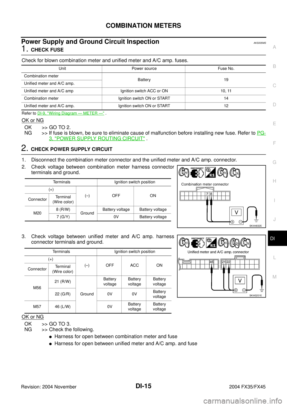
2. Check voltage between combination meter harness connector
terminals and ground.
3. Check voltage between unified meter and A/C amp. harness
connector terminals and ground.
OK or NG
OK >> GO TO 3.
NG >> Check the following.
�Harness for open between combination meter and fuse
�Harness for open between unified meter and A/C amp. and fuse
Unit Power source Fuse No.
Combination meter
Battery 19
Unified meter and A/C amp.
Unified meter and A/C amp Ignition switch ACC or ON 10, 11
Combination meter Ignition switch ON or START 14
Unified meter and A/C amp. Ignition switch ON or START 12
Terminals Ignition switch position
(+)
(–) OFF ON
ConnectorTe r m i n a l
(Wire color)
M208 (R/W)
GroundBattery voltage Battery voltage
7 (G/Y) 0V Battery voltage
SKIA4832E
Terminals Ignition switch position
(+)
(–) OFF ACC ON
ConnectorTerminal
(Wire color)
M5621 (R/W)
GroundBattery
voltageBattery
voltageBattery
voltage
22 (G/R) 0V 0VBattery
voltage
M57 46 (L/W) 0VBattery
voltageBattery
voltage
SKIA5201E
Page 1308 of 4449
WARNING CHIME
DI-65
C
D
E
F
G
H
I
J
L
MA
B
DI
Revision: 2004 November 2004 FX35/FX45
Preliminary CheckAKS005NS
CHECK POWER SUPPLY AND GROUND CIRCUIT
1. CHECK FUSE AND FUSIBLE LINK
Check BCM fuses and fusible link for blown-out.
Refer to DI-59, "Wiring Diagram — CHIME —" .
OK or NG
OK >> GO TO 2.
NG >> If fuse or fusible link is blown, be sure to eliminate cause of malfunction before installing new fuse
or fusible link. Refer to PG-3, "
POWER SUPPLY ROUTING CIRCUIT" .
2. CHECK POWER SUPPLY CIRCUIT
1. Disconnect BCM connector.
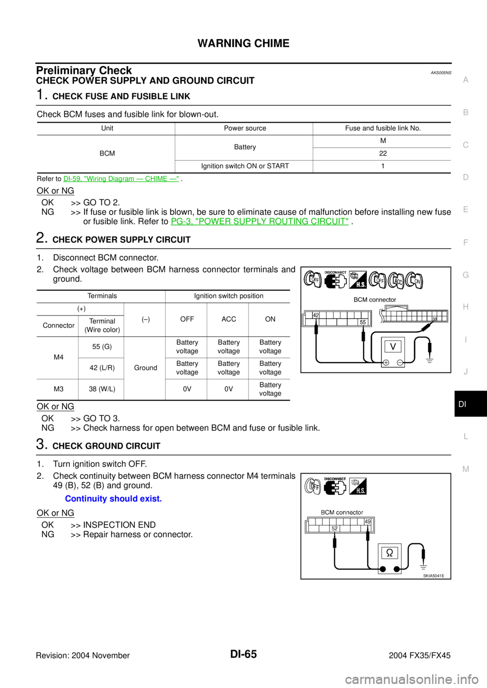
2. Check voltage between BCM harness connector terminals and
ground.
OK or NG
OK >> GO TO 3.
NG >> Check harness for open between BCM and fuse or fusible link.
3. CHECK GROUND CIRCUIT
1. Turn ignition switch OFF.
2. Check continuity between BCM harness connector M4 terminals
49 (B), 52 (B) and ground.
OK or NG
OK >> INSPECTION END
NG >> Repair harness or connector.
Unit Power source Fuse and fusible link No.
BCMBatteryM
22
Ignition switch ON or START 1
Terminals Ignition switch position
(+)
(–) OFF ACC ON
ConnectorTerminal
(Wire color)
M455 (G)
GroundBattery
voltageBattery
voltageBattery
voltage
42 (L/R)Battery
voltageBattery
voltageBattery
voltage
M3 38 (W/L) 0V 0VBattery
voltage
Continuity should exist.
SKIA5041E
Page 1334 of 4449
REAR VIEW MONITOR
DI-91
C
D
E
F
G
H
I
J
L
MA
B
DI
Revision: 2004 November 2004 FX35/FX45
Power Supply and Ground Circuit InspectionAKS0068M
1. CHECK FUSE
Make sure the fuses for rear view camera control unit is blown.
OK or NG
OK >> GO TO 2.
NG >> If fuse is blown, be sure to eliminate cause of malfunction before installing new fuse. Refer to PG-
3, "POWER SUPPLY ROUTING CIRCUIT" .
2. CHECK POWER SUPPLY CIRCUIT
1. Disconnect rear view camera control unit connector.
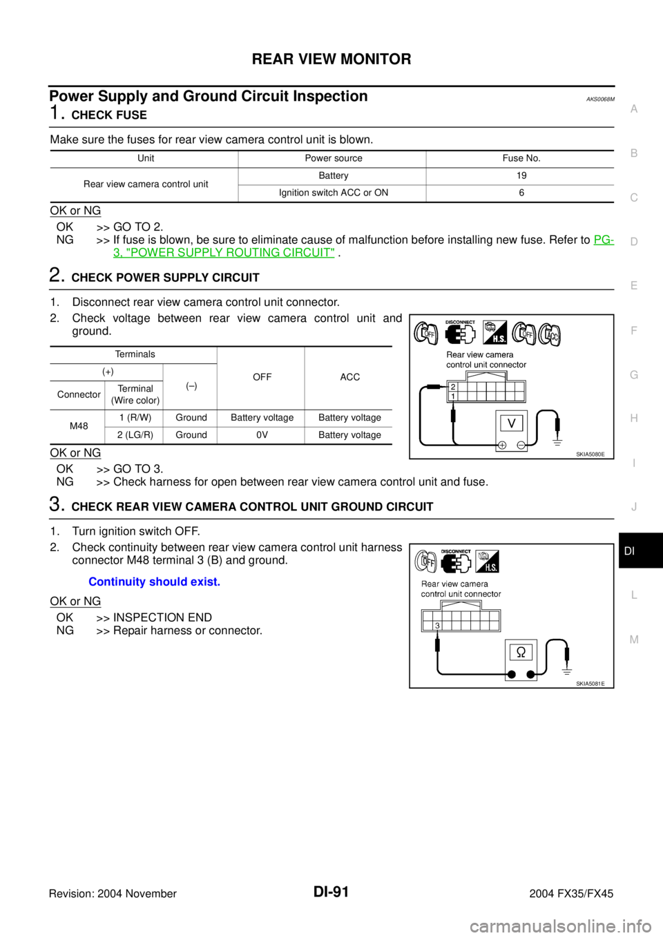
2. Check voltage between rear view camera control unit and
ground.
OK or NG
OK >> GO TO 3.
NG >> Check harness for open between rear view camera control unit and fuse.
3. CHECK REAR VIEW CAMERA CONTROL UNIT GROUND CIRCUIT
1. Turn ignition switch OFF.
2. Check continuity between rear view camera control unit harness
connector M48 terminal 3 (B) and ground.
OK or NG
OK >> INSPECTION END
NG >> Repair harness or connector.
Unit Power source Fuse No.
Rear view camera control unitBattery 19
Ignition switch ACC or ON 6
Terminals
OFF ACC (+)
(–)
ConnectorTerminal
(Wire color)
M481 (R/W) Ground Battery voltage Battery voltage
2 (LG/R) Ground 0V Battery voltage
SKIA5080E
Continuity should exist.
SKIA5081E
Page 1379 of 4449
![INFINITI FX35 2004 Service Manual EC-38
[VQ35DE]
BASIC SERVICE PROCEDURE
Revision: 2004 November 2004 FX35/FX45
2. Connect No. 1 ignition coil and No. 1 spark plug with suitable
high-tension wire as shown, and attach timing light clam INFINITI FX35 2004 Service Manual EC-38
[VQ35DE]
BASIC SERVICE PROCEDURE
Revision: 2004 November 2004 FX35/FX45
2. Connect No. 1 ignition coil and No. 1 spark plug with suitable
high-tension wire as shown, and attach timing light clam](/manual-img/42/57021/w960_57021-1378.png)
EC-38
[VQ35DE]
BASIC SERVICE PROCEDURE
Revision: 2004 November 2004 FX35/FX45
2. Connect No. 1 ignition coil and No. 1 spark plug with suitable
high-tension wire as shown, and attach timing light clamp to this
wire.
3. Check ignition timing.
Idle Speed/Ignition Timing/Idle Mixture Ratio AdjustmentABS006KD
PREPARATION
1. Make sure that the following parts are in good order.
�Battery
�Ignition system
�Engine oil and coolant levels
�Fuses
�ECM harness connector
�Vacuum hoses
�Air intake system
(Oil filler cap, oil level gauge, etc.)
�Fuel pressure
�Engine compression
�Throttle valve
�Evaporative emission system
2. On air conditioner equipped models, checks should be carried out while the air conditioner is OFF.
3. On automatic transmission equipped models, when checking idle rpm, ignition timing and mixture ratio,
checks should be carried out while shift lever is in N position.
4. When measuring CO percentage, insert probe more than 40 cm (15.7 in) into tail pipe.
5. Turn OFF headlamp, heater blower, rear window defogger.
PBIB1573E
SEF166Y
PBIB1602E
Page 2028 of 4449
BASIC SERVICE PROCEDURE
EC-687
[VK45DE]
C
D
E
F
G
H
I
J
K
L
MA
EC
Revision: 2004 November 2004 FX35/FX45
Idle Speed/Ignition Timing/Idle Mixture Ratio AdjustmentABS00BZD
PREPARATION
1. Make sure that the following parts are in good order.
�Battery
�Ignition system
�Engine oil and coolant levels
�Fuses
�ECM harness connector
�Va c u u m h o s e s
�Air intake system
(Oil filler cap, oil level gauge, etc.)
�Fuel pressure
�Engine compression
�Throttle valve
�Evaporative emission system
2. On air conditioner equipped models, checks should be carried out while the air conditioner is OFF.
3. On automatic transmission equipped models, when checking idle rpm, ignition timing and mixture ratio,
checks should be carried out while shift lever is in N position.
4. When measuring CO percentage, insert probe more than 40 cm (15.7 in) into tail pipe.
5. Turn OFF headlamp, heater blower, rear window defogger.
6. Keep front wheels pointed straight ahead.
Page 3572 of 4449
HEADLAMP - XENON TYPE -
LT-17
C
D
E
F
G
H
I
J
L
MA
B
LT
Revision: 2004 November 2004 FX35/FX45
Preliminary CheckAKS007MI
CHECK POWER SUPPLY AND GROUND CIRCUIT
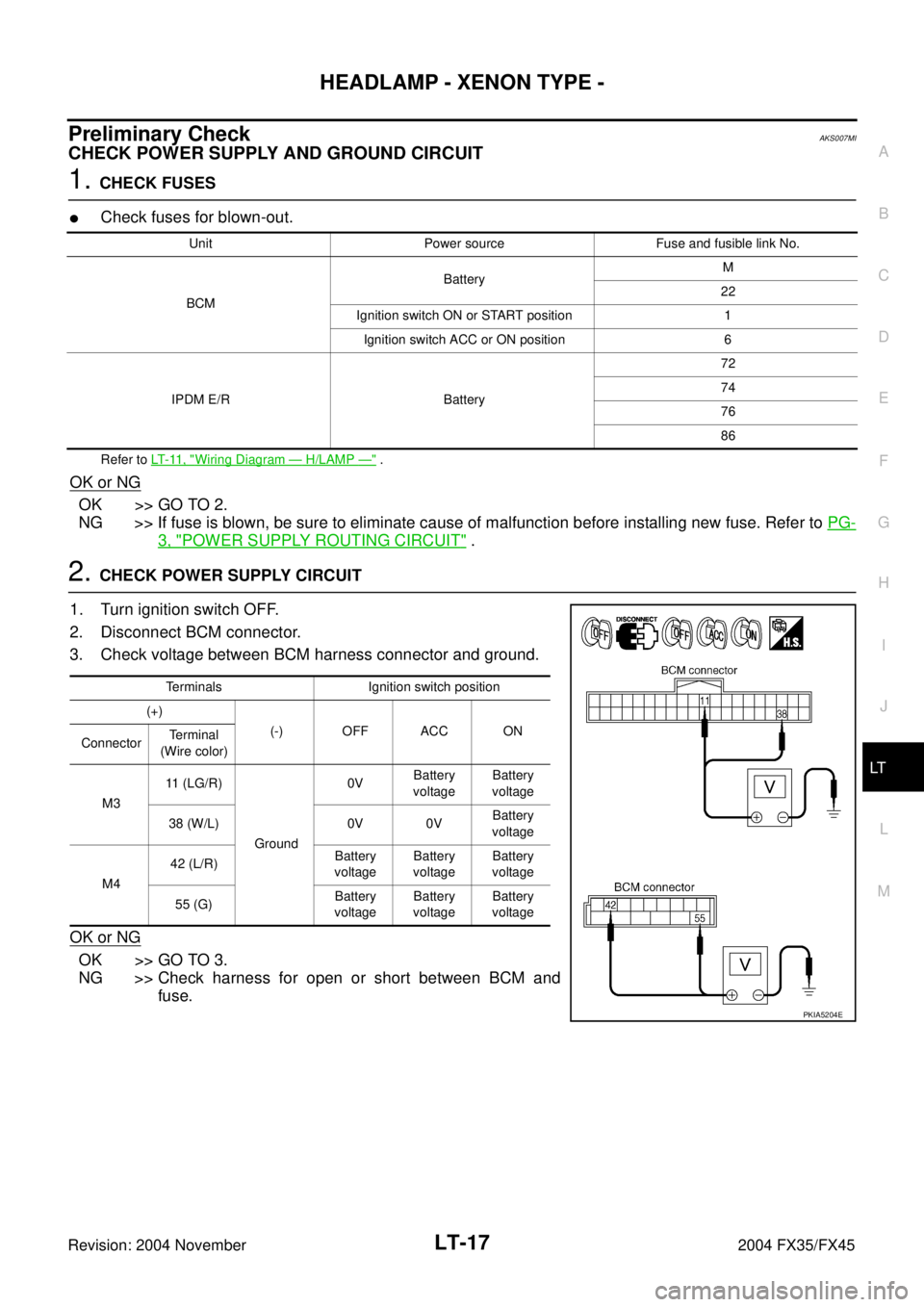
1. CHECK FUSES
�Check fuses for blown-out.
Refer to LT- 11 , "Wiring Diagram — H/LAMP —" .
OK or NG
OK >> GO TO 2.
NG >> If fuse is blown, be sure to eliminate cause of malfunction before installing new fuse. Refer to PG-
3, "POWER SUPPLY ROUTING CIRCUIT" .
2. CHECK POWER SUPPLY CIRCUIT
1. Turn ignition switch OFF.
2. Disconnect BCM connector.
3. Check voltage between BCM harness connector and ground.
OK or NG
OK >> GO TO 3.
NG >> Check harness for open or short between BCM and
fuse.
Unit Power source Fuse and fusible link No.
BCMBatteryM
22
Ignition switch ON or START position 1
Ignition switch ACC or ON position 6
IPDM E/R Battery72
74
76
86
Terminals Ignition switch position
(+)
(-) OFF ACC ON
ConnectorTerminal
(Wire color)
M311 (LG/R)
Ground0VBattery
voltageBattery
voltage
38 (W/L) 0V 0VBattery
voltage
M442 (L/R)Battery
voltageBattery
voltageBattery
voltage
55 (G)Battery
voltageBattery
voltageBattery
voltage
PKIA5204E
Page 3588 of 4449

HEADLAMP - XENON TYPE -
LT-33
C
D
E
F
G
H
I
J
L
MA
B
LT
Revision: 2004 November 2004 FX35/FX45
CAUTION:AKS007MT
�Installation or removal of the connector must be done with the lighting switch OFF.
�When the lamp is illuminated (when the lighting switch is ON), do not touch the harness, HID control unit,
inside of the lamp, or the lamp metal parts.
�To check illumination, temporarily install lamp in the vehicle. Be sure to connect power at the vehicle-side
connector.
�If the error can be traced directly to the electrical system, first check for items such as burned-out fuses
and fusible links, broken wires or loose connectors, pulled-out terminals, and improper connections.
�Do not work with wet hands.
�Using a tester for HID control unit circuit trouble diagnosis is prohibited.
�Disassembling the HID control unit or harnesses (bulb socket harness, ECM harness) is prohibited.
�Immediately after illumination, the light intensity and color will fluctuate, but there is nothing wrong.
�When the bulb has reached the end of its lifetime, the brightness may drop significantly, it may flash
repeatedly, or the light may turn a reddish color.
Xenon Headlamp Trouble DiagnosisAKS007MU
1. CHECK 1: XENON HEADLAMP LIGHTING
Install normal xenon bulb to corresponding xenon bulb headlamp, and check if lamp lights up.
OK or NG
OK >> Replace xenon bulb.
NG >> GO TO 2.
2. CHECK 2: XENON HEADLAMP LIGHTING
Install normal HID control unit to corresponding xenon headlamp, and check if lamp lights up.
OK or NG
OK >> Replace HID control unit.
NG >> GO TO 3.
3. CHECK 3: XENON HEADLAMP LIGHTING
Install normal xenon lamp housing assembly to corresponding xenon headlamp, and check if lamp lights up.
OK or NG
OK >> Malfunction in starter (boosting circuit) in xenon headlamp housing. (Replace xenon headlamp
housing assembly.)
NG >> INSPECTION END