Page 2747 of 4449
![INFINITI FX35 2004 Service Manual EM-22
[VQ35DE]
INTAKE MANIFOLD COLLECTOR
Revision: 2004 November 2004 FX35/FX45
INSTALLATION
Note to the following, and install in the reverse order of removal.
Part Installation Direction
Referring t](/manual-img/42/57021/w960_57021-2746.png "INFINITI FX35 2004 Service Manual EM-22
[VQ35DE]
INTAKE MANIFOLD COLLECTOR
Revision: 2004 November 2004 FX35/FX45
INSTALLATION
Note to the following, and install in the reverse order of removal.
Part Installation Direction
Referring t")
EM-22
[VQ35DE]
INTAKE MANIFOLD COLLECTOR
Revision: 2004 November 2004 FX35/FX45
INSTALLATION
Note to the following, and install in the reverse order of removal.
Part Installation Direction
Referring to front marks, install parts shown in figure.
Intake Manifold Collector (Lower)
Tighten in numerical order as shown in the figure.
NOTE:
Tighten mounting bolts to secure gasket (lower), intake manifold col-
lector (lower), gasket (upper), and intake manifold collector cover.
Intake Manifold Collector (Upper)
�If stud bolts were removed, install them and tighten to the speci-
fied torque below.
�Shank length under bolt head varies with bolt location. Install
bolts while referring to numbers shown below and in figure. (Bolt
length does not include pilot portion.)
�Tighten in numerical order as shown in the figure.
Water Hose
�Insert hose by 27 to 32 mm (1.06 to 1.26 in) from connector end.
PBIC0776E
PBIC0774E
: 5.9 N·m (0.6 kg-m, 52 in-lb)
Bolt
M6 × 25 mm (0.98 in) : 7, 8, 10, 11, 13, 14, 15, 16, 18
M6 × 45 mm (1.77 in) : 2, 4, 5
M6 × 60 mm (2.36 in) : 1, 3, 6, 9
M6 Nut : 12, 17
PBIC0773E
Page 2777 of 4449
EM-52
[VQ35DE]
ROCKER COVER
Revision: 2004 November 2004 FX35/FX45
6. Loosen bolts in the reverse order shown in the figure (with
power tool).
7. Remove rocker cover gaskets from rocker covers.
8. Use scraper to remove all trances of liquid gasket from cylinder head and camshaft bracket (No. 1).
CAUTION:
Do not scratch or damage the mating surface when cleaning off old liquid gasket.
INSTALLATION
1. Apply liquid gasket of 3.0 mm (0.12 in) diameter to position
shown in the figure (both edges of No. 1 camshaft bracket) (on
both banks).
�First, apply it to engine longitudinal direction [5.0 mm (0.197
in) + 5.0 mm (0.197 in) side in figure].
Use Genuine RTV Silicone Sealant or equivalent. Refer to
GI-48, "
RECOMMENDED CHEMICAL PRODUCTS AND
SEALANTS" .
2. Install new rocker cover gasket to rocker cover.
3. Install rocker cover.
�Check if rocker cover gasket is dropped from installation groove of rocker cover.
KBIA0985E
PBIC0786E
Page 2793 of 4449
![INFINITI FX35 2004 Service Manual EM-68
[VQ35DE]
TIMING CHAIN
Revision: 2004 November 2004 FX35/FX45
28. Remove internal chain guide, tension guide and slack guide.
NOTE:
Tension guide can be removed after removing timing chain (pri-](/manual-img/42/57021/w960_57021-2792.png "INFINITI FX35 2004 Service Manual EM-68
[VQ35DE]
TIMING CHAIN
Revision: 2004 November 2004 FX35/FX45
28. Remove internal chain guide, tension guide and slack guide.
NOTE:
Tension guide can be removed after removing timing chain (pri-")
EM-68
[VQ35DE]
TIMING CHAIN
Revision: 2004 November 2004 FX35/FX45
28. Remove internal chain guide, tension guide and slack guide.
NOTE:
Tension guide can be removed after removing timing chain (pri-
mary).
29. Remove timing chain (primary), tension guide and crankshaft sprocket.
CAUTION:
After removing timing chain, do not turn crankshaft and camshaft separately, or valves will strike
piston heads.
30. Remove timing chain (secondary) and camshaft sprockets as the following:
a. Attach a suitable stopper pin to right and left camshaft chain ten-
sioners (for secondary timing chains).
NOTE:
For removal and installation of secondary chain tensioner, refer
to EM-82, "
CAMSHAFT" . (Removing No. 1 camshaft bracket is
required.)
b. Remove intake and exhaust camshaft sprocket bolts.
�Apply paint to timing chain and camshaft sprockets for align-
ment during installation.
�Secure the hexagonal portion of camshaft using a wrench to
loosen mounting bolts.
c. Remove timing chain (secondary) together with camshaft sprockets.
�Turn camshaft slightly to secure slackness of timing chain on timing chain tensioner (secondary) side.
PBIC2266E
SEM923G
KBIA1698J
Page 2798 of 4449
TIMING CHAIN
EM-73
[VQ35DE]
C
D
E
F
G
H
I
J
K
L
MA
EM
Revision: 2004 November 2004 FX35/FX45
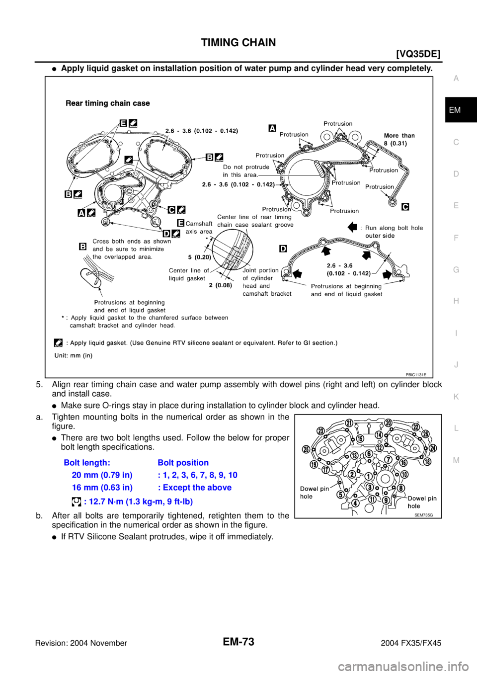
�Apply liquid gasket on installation position of water pump and cylinder head very completely.
5. Align rear timing chain case and water pump assembly with dowel pins (right and left) on cylinder block
and install case.
�Make sure O-rings stay in place during installation to cylinder block and cylinder head.
a. Tighten mounting bolts in the numerical order as shown in the
figure.
�There are two bolt lengths used. Follow the below for proper
bolt length specifications.
b. After all bolts are temporarily tightened, retighten them to the
specification in the numerical order as shown in the figure.
�If RTV Silicone Sealant protrudes, wipe it off immediately.Bolt length: Bolt position
20 mm (0.79 in) : 1, 2, 3, 6, 7, 8, 9, 10
16 mm (0.63 in) : Except the above
: 12.7 N·m (1.3 kg-m, 9 ft-lb)
PBIC1131E
SEM735G
Page 2808 of 4449
![INFINITI FX35 2004 Service Manual CAMSHAFT
EM-83
[VQ35DE]
C
D
E
F
G
H
I
J
K
L
MA
EM
Revision: 2004 November 2004 FX35/FX45
REMOVAL
1. Remove front timing chain case, camshaft sprocket, timing chain and rear timing chain case. Refer to](/manual-img/42/57021/w960_57021-2807.png "INFINITI FX35 2004 Service Manual CAMSHAFT
EM-83
[VQ35DE]
C
D
E
F
G
H
I
J
K
L
MA
EM
Revision: 2004 November 2004 FX35/FX45
REMOVAL
1. Remove front timing chain case, camshaft sprocket, timing chain and rear timing chain case. Refer to")
CAMSHAFT
EM-83
[VQ35DE]
C
D
E
F
G
H
I
J
K
L
MA
EM
Revision: 2004 November 2004 FX35/FX45
REMOVAL
1. Remove front timing chain case, camshaft sprocket, timing chain and rear timing chain case. Refer to EM-
63, "TIMING CHAIN" .
2. If necessary, remove camshaft position sensor (PHASE) (right
and left banks) from cylinder head back side.
CAUTION:
�Handle carefully to avoid dropping and shocks.
�Do not disassemble.
�Do not allow metal powder to adhere to magnetic part at
sensor tip.
�Do not place sensors in a location where they are
exposed to magnetism.
3. Remove intake valve timing control solenoid valve from No.1
camshaft bracket.
4. Remove intake and exhaust camshaft brackets.
�Mark camshafts, camshaft brackets, and bolts so they are
placed in the same position and direction for installation.
�Equally loosen camshaft bracket bolts in several steps in the
reverse order as shown in the figure.
5. Remove camshaft.
6. Remove valve lifter.
�Identify installation positions, and store them without mixing them up.
KBIA1046E
SEM443GA
PBIC2050E
Page 2814 of 4449
![INFINITI FX35 2004 Service Manual CAMSHAFT
EM-89
[VQ35DE]
C
D
E
F
G
H
I
J
K
L
MA
EM
Revision: 2004 November 2004 FX35/FX45
5. Tighten camshaft brackets in the following steps, in numerical
order as shown in the figure.
a. Tighten No.](/manual-img/42/57021/w960_57021-2813.png "INFINITI FX35 2004 Service Manual CAMSHAFT
EM-89
[VQ35DE]
C
D
E
F
G
H
I
J
K
L
MA
EM
Revision: 2004 November 2004 FX35/FX45
5. Tighten camshaft brackets in the following steps, in numerical
order as shown in the figure.
a. Tighten No.")
CAMSHAFT
EM-89
[VQ35DE]
C
D
E
F
G
H
I
J
K
L
MA
EM
Revision: 2004 November 2004 FX35/FX45
5. Tighten camshaft brackets in the following steps, in numerical
order as shown in the figure.
a. Tighten No. 7 to 10, then tighten No. 1 to 6 in order as shown.
b. Tighten all bolts in numerical order as shown.
c. Tighten all bolts in the numerical order as shown.
CAUTION:
After tightening mounting bolts of No. 1 camshaft brackets
(No. 1), be sure to wipe off excessive liquid gasket from the
parts list below.
�Mating surface of rocker cover
�Mating surface of rear timing chain case
6. Measure difference in levels between front end faces of No. 1
camshaft bracket and cylinder head.
�If measurement is outside the specified range, re-install cam-
shaft and camshaft bracket.
7. Inspect and adjust valve clearance. Refer to EM-89, "
Valve Clearance" .
8. Install in the reverse order of removal after this step.
Va l v e C l e a r a n c eABS004XG
INSPECTION
Perform inspection as follows after removal, installation or replace-
ment of camshaft or valve-related parts, or if there is unusual engine
conditions regarding valve clearance.
1. Remove right and left rocker covers with power tool. Refer to EM-51, "
ROCKER COVER" .
2. Measure valve clearance as below:
a. Set No. 1 cylinder at TDC of its compression stroke. : 1.96 N·m (0.20 kg-m, 1 ft-lb)
: 5.88 N·m (0.60 kg-m, 4 ft-lb)
: 10.4 N·m (1.1 kg-m, 8 ft-lb)
PBIC2050E
Standard : –0.14 to 0.14 mm (–0.0055 to 0.0055 in)
EMQ0044D
SEM713A
Page 2825 of 4449
![INFINITI FX35 2004 Service Manual EM-100
[VQ35DE]
CYLINDER HEAD
Revision: 2004 November 2004 FX35/FX45
NOTE:
At the time of the start of this procedure front suspension member is removed, and cylinder head is
hanged by hoist with engi](/manual-img/42/57021/w960_57021-2824.png "INFINITI FX35 2004 Service Manual EM-100
[VQ35DE]
CYLINDER HEAD
Revision: 2004 November 2004 FX35/FX45
NOTE:
At the time of the start of this procedure front suspension member is removed, and cylinder head is
hanged by hoist with engi")
EM-100
[VQ35DE]
CYLINDER HEAD
Revision: 2004 November 2004 FX35/FX45
NOTE:
At the time of the start of this procedure front suspension member is removed, and cylinder head is
hanged by hoist with engine slinger installed.
3. Release hoist from hanging, then remove engine slinger.
4. Remove the following components and related parts:
�Fuel tube and fuel injector assembly. Refer to EM-45, "FUEL INJECTOR AND FUEL TUBE" .
�Intake manifold. Refer to EM-24, "INTAKE MANIFOLD" .
�Exhaust manifold. Refer to EM-26, "EXHAUST MANIFOLD AND THREE WAY CATALYST" .
�Water inlet and thermostat assembly. Refer to CO-26, "WATER INLET AND THERMOSTAT ASSEM-
BLY" .
�Water outlet and water piping. Refer to CO-28, "WATER OUTLET AND WATER PIPING" .
5. Remove cylinder head loosening bolts with power tool in reverse
order shown in the figure and using cylinder head bolt wrench
(commercial service tool).
6. Remove cylinder head gaskets.
INSPECTION AFTER REMOVAL
Outer Diameter of Cylinder Head Bolts
�Cylinder head bolts are tightened by plastic zone tightening
method. Whenever the size difference between d1 and d2
exceeds the limit, replace them with new one.
�If reduction of outer diameter appears in a position other than
d2, use it as d2 point.
Cylinder Head Distortion
NOTE:
When performing this inspection, cylinder block distortion should be also checking. Refer to EM-139, "
CYLIN-
DER BLOCK DISTORTION" .
1. Using scraper, wipe off oil, scale, gasket, sealant and carbon deposits from surface of cylinder head.
CAUTION:
Do not allow gasket fragments to enter engine oil or engine coolant passages.
PBIC2057E
Limit (d1 - d2) : 0.11 mm (0.0043 in)
SEM957E
Page 2826 of 4449
CYLINDER HEAD
EM-101
[VQ35DE]
C
D
E
F
G
H
I
J
K
L
MA
EM
Revision: 2004 November 2004 FX35/FX45
2. At each of several locations on bottom surface of cylinder head,
measure distortion in six directions.
�If it exceeds the limit, replace cylinder head.
INSTALLATION
1. Install cylinder head gasket.
2. Turn crankshaft until No. 1 piston is set at TDC on the compres-
sion stroke.
�Crankshaft key should line up with the right bank cylinder cen-
ter line as shown.
3. Install cylinder head follow the steps below to tighten cylinder
head bolts in the order shown in figure.
a. Tighten all bolts.
b. Completely loosen.
CAUTION:
In step “b”, loosen bolts in the reverse order of that indi-
cated in figure.
c. Tighten all bolts.Limit : 0.1 mm (0.004 in)
SEM861E
SEM532G
: 98.1 N·m (10 kg-m, 72 ft-lb)
: 0 N·m (0 kg-m, 0 ft-lb)
: 39.2 N·m (4.0 kg-m, 29 ft-lb)
PBIC2057E
![INFINITI FX35 2004 Service Manual EM-52
[VQ35DE]
ROCKER COVER
Revision: 2004 November 2004 FX35/FX45
6. Loosen bolts in the reverse order shown in the figure (with
power tool).
7. Remove rocker cover gaskets from rocker covers.
8. Use](/manual-img/42/57021/w960_57021-2776.png "INFINITI FX35 2004 Service Manual EM-52
[VQ35DE]
ROCKER COVER
Revision: 2004 November 2004 FX35/FX45
6. Loosen bolts in the reverse order shown in the figure (with
power tool).
7. Remove rocker cover gaskets from rocker covers.
8. Use")
![INFINITI FX35 2004 Service Manual CYLINDER HEAD
EM-101
[VQ35DE]
C
D
E
F
G
H
I
J
K
L
MA
EM
Revision: 2004 November 2004 FX35/FX45
2. At each of several locations on bottom surface of cylinder head,
measure distortion in six directions.](/manual-img/42/57021/w960_57021-2825.png "INFINITI FX35 2004 Service Manual CYLINDER HEAD
EM-101
[VQ35DE]
C
D
E
F
G
H
I
J
K
L
MA
EM
Revision: 2004 November 2004 FX35/FX45
2. At each of several locations on bottom surface of cylinder head,
measure distortion in six directions.")