2004 INFINITI FX35 Automatic Air conditioner
[x] Cancel search: Automatic Air conditionerPage 3126 of 4449

HOW TO USE THIS MANUAL
GI-23
C
D
E
F
G
H
I
J
K
L
MB
GI
Revision: 2004 November 2004 FX35/FX45
AbbreviationsAAS000E3
The following ABBREVIATIONS are used:
ABBREVIATION DESCRIPTION
A/C Air Conditioner
A/T Automatic Transaxle/Transmission
ATF Automatic Transmission Fluid
D
1Drive range 1st gear
D
2Drive range 2nd gear
D
3Drive range 3rd gear
D
4Drive range 4th gear
FR, RR Front, Rear
LH, RH Left-Hand, Right-Hand
M/T Manual Transaxle/Transmission
OD Overdrive
P/S Power Steering
SAE Society of Automotive Engineers, Inc.
SDS Service Data and Specifications
SST Special Service Tools
2WD 2-Wheel Drive
2
22nd range 2nd gear
2
12nd range 1st gear
1
21st range 2nd gear
1
11st range 1st gear
Page 3275 of 4449

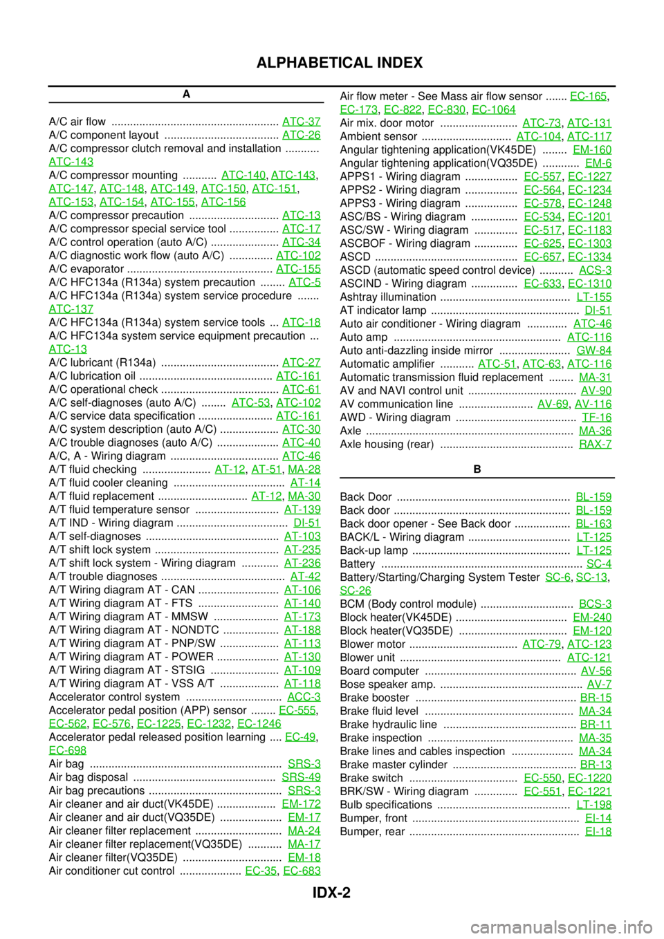
IDX-2
ALPHABETICAL INDEX
A
A/C air flow ...................................................... ATC-37
A/C component layout ..................................... ATC-26
A/C compressor clutch removal and installation ...........
ATC-143
A/C compressor mounting ........... ATC-140, ATC-143,
ATC-147
, ATC-148, ATC-149, ATC-150, ATC-151,
ATC-153
, ATC-154, ATC-155, ATC-156
A/C compressor precaution ............................. ATC-13
A/C compressor special service tool ................ ATC-17
A/C control operation (auto A/C) ...................... ATC-34
A/C diagnostic work flow (auto A/C) .............. ATC-102
A/C evaporator ............................................... ATC-155
A/C HFC134a (R134a) system precaution ........ ATC-5
A/C HFC134a (R134a) system service procedure .......
ATC-137
A/C HFC134a (R134a) system service tools ... ATC-18
A/C HFC134a system service equipment precaution ...
ATC-13
A/C lubricant (R134a) ...................................... ATC-27
A/C lubrication oil ........................................... ATC-161
A/C operational check ...................................... ATC-61
A/C self-diagnoses (auto A/C) ........ ATC-53, ATC-102
A/C service data specification ........................ ATC-161
A/C system description (auto A/C) ................... ATC-30
A/C trouble diagnoses (auto A/C) .................... ATC-40
A/C, A - Wiring diagram ................................... ATC-46
A/T fluid checking ...................... AT-12, AT-51, MA-28
A/T fluid cooler cleaning .................................... AT-14
A/T fluid replacement ............................. AT-12, MA-30
A/T fluid temperature sensor ........................... AT-139
A/T IND - Wiring diagram .................................... DI-51
A/T self-diagnoses ........................................... AT-103
A/T shift lock system ........................................ AT-235
A/T shift lock system - Wiring diagram ............ AT-236
A/T trouble diagnoses ........................................ AT-42
A/T Wiring diagram AT - CAN .......................... AT-106
A/T Wiring diagram AT - FTS .......................... AT-140
A/T Wiring diagram AT - MMSW ..................... AT-173
A/T Wiring diagram AT - NONDTC .................. AT-188
A/T Wiring diagram AT - PNP/SW ................... AT-113
A/T Wiring diagram AT - POWER .................... AT-130
A/T Wiring diagram AT - STSIG ...................... AT-109
A/T Wiring diagram AT - VSS A/T ................... AT-118
Accelerator control system ............................... ACC-3
Accelerator pedal position (APP) sensor ........ EC-555,
EC-562
, EC-576, EC-1225, EC-1232, EC-1246
Accelerator pedal released position learning .... EC-49,
EC-698
Air bag .............................................................. SRS-3
Air bag disposal .............................................. SRS-49
Air bag precautions ........................................... SRS-3
Air cleaner and air duct(VK45DE) ................... EM-172
Air cleaner and air duct(VQ35DE) .................... EM-17
Air cleaner filter replacement ............................ MA-24
Air cleaner filter replacement(VQ35DE) ........... MA-17
Air cleaner filter(VQ35DE) ................................ EM-18
Air conditioner cut control .................... EC-35, EC-683
Air flow meter - See Mass air flow sensor ....... EC-165,
EC-173
, EC-822, EC-830, EC-1064
Air mix. door motor ......................... ATC-73, ATC-131
Ambient sensor ............................. ATC-104, ATC-117
Angular tightening application(VK45DE) ........ EM-160
Angular tightening application(VQ35DE) ............ EM-6
APPS1 - Wiring diagram ................. EC-557, EC-1227
APPS2 - Wiring diagram ................. EC-564, EC-1234
APPS3 - Wiring diagram ................. EC-578, EC-1248
ASC/BS - Wiring diagram ............... EC-534, EC-1201
ASC/SW - Wiring diagram .............. EC-517, EC-1183
ASCBOF - Wiring diagram .............. EC-625, EC-1303
ASCD .............................................. EC-657, EC-1334
ASCD (automatic speed control device) ........... ACS-3
ASCIND - Wiring diagram ............... EC-633, EC-1310
Ashtray illumination .......................................... LT-155
AT indicator lamp ................................................ DI-51
Auto air conditioner - Wiring diagram ............. ATC-46
Auto amp ...................................................... ATC-116
Auto anti-dazzling inside mirror ....................... GW-84
Automatic amplifier ........... ATC-51, ATC-63, ATC-116
Automatic transmission fluid replacement ........ MA-31
AV and NAVI control unit ................................... AV-90
AV communication line ........................ AV-69, AV-116
AWD - Wiring diagram ....................................... TF-16
Axle ................................................................... MA-36
Axle housing (rear) ........................................... RAX-7
B
Back Door ........................................................ BL-159
Back door ......................................................... BL-159
Back door opener - See Back door .................. BL-163
BACK/L - Wiring diagram ................................. LT-125
Back-up lamp ................................................... LT-125
Battery ................................................................. SC-4
Battery/Starting/Charging System Tester SC-6, SC-13,
SC-26
BCM (Body control module) .............................. BCS-3
Block heater(VK45DE) .................................... EM-240
Block heater(VQ35DE) ................................... EM-120
Blower motor ................................... ATC-79, ATC-123
Blower unit .................................................... ATC-121
Board computer ................................................. AV-56
Bose speaker amp. .............................................. AV-7
Brake booster .................................................... BR-15
Brake fluid level ................................................ MA-34
Brake hydraulic line ........................................... BR-11
Brake inspection ............................................... MA-35
Brake lines and cables inspection .................... MA-34
Brake master cylinder ........................................ BR-13
Brake switch ................................... EC-550, EC-1220
BRK/SW - Wiring diagram .............. EC-551, EC-1221
Bulb specifications ........................................... LT-198
Bumper, front ...................................................... EI-14
Bumper, rear ....................................................... EI-18
Page 3793 of 4449

MA-6
GENERAL MAINTENANCE
Revision: 2004 November 2004 FX35/FX45
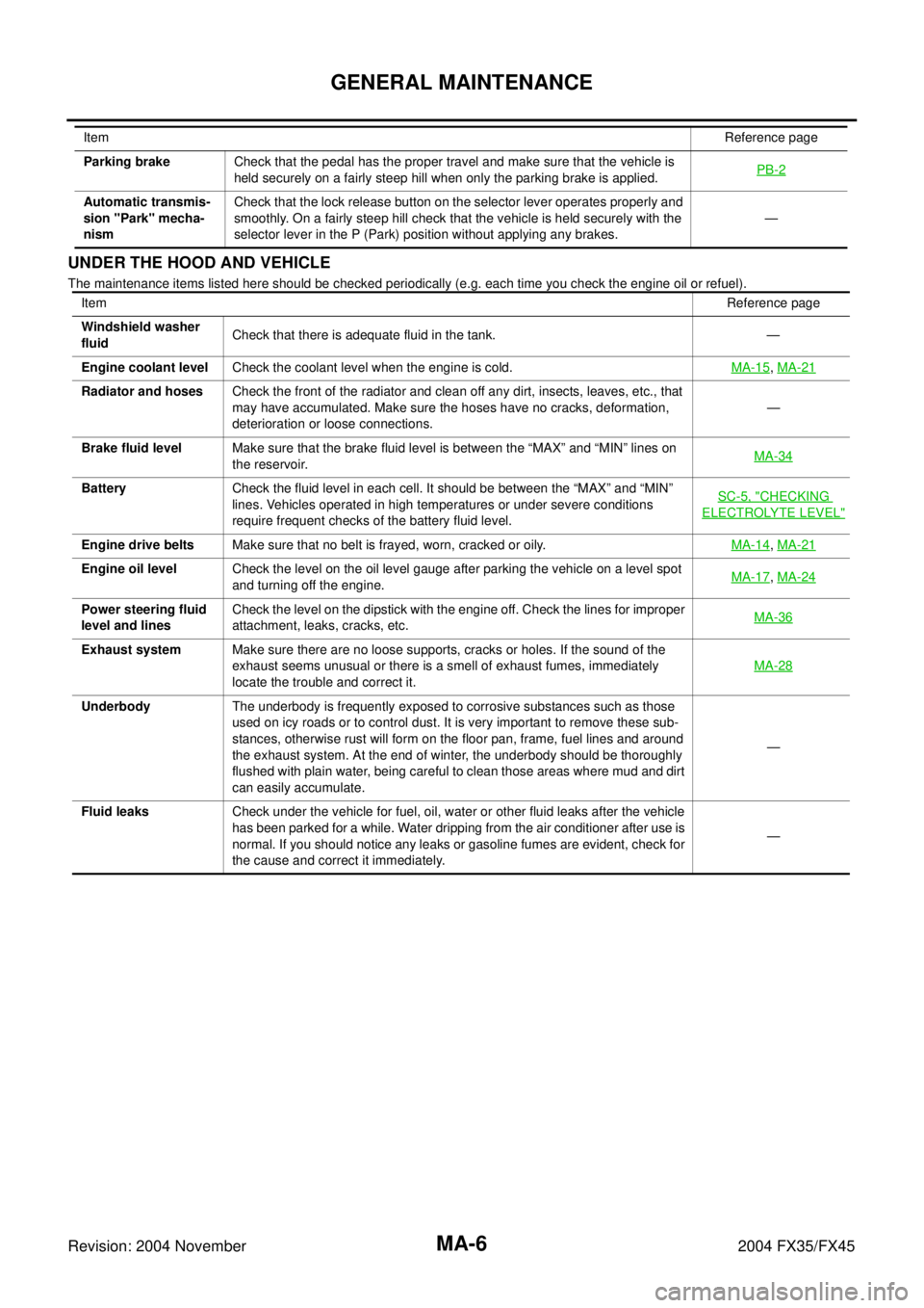
UNDER THE HOOD AND VEHICLE
The maintenance items listed here should be checked periodically (e.g. each time you check the engine oil or refuel).Parking brakeCheck that the pedal has the proper travel and make sure that the vehicle is
held securely on a fairly steep hill when only the parking brake is applied.PB-2
Automatic transmis-
sion "Park" mecha-
nismCheck that the lock release button on the selector lever operates properly and
smoothly. On a fairly steep hill check that the vehicle is held securely with the
selector lever in the P (Park) position without applying any brakes.— ItemReference page
ItemReference page
Windshield washer
fluidCheck that there is adequate fluid in the tank. —
Engine coolant levelCheck the coolant level when the engine is cold.MA-15
, MA-21
Radiator and hosesCheck the front of the radiator and clean off any dirt, insects, leaves, etc., that
may have accumulated. Make sure the hoses have no cracks, deformation,
deterioration or loose connections.—
Brake fluid levelMake sure that the brake fluid level is between the “MAX” and “MIN” lines on
the reservoir.MA-34
BatteryCheck the fluid level in each cell. It should be between the “MAX” and “MIN”
lines. Vehicles operated in high temperatures or under severe conditions
require frequent checks of the battery fluid level.SC-5, "
CHECKING
ELECTROLYTE LEVEL"
Engine drive beltsMake sure that no belt is frayed, worn, cracked or oily.MA-14, MA-21
Engine oil levelCheck the level on the oil level gauge after parking the vehicle on a level spot
and turning off the engine.MA-17, MA-24
Power steering fluid
level and linesCheck the level on the dipstick with the engine off. Check the lines for improper
attachment, leaks, cracks, etc.MA-36
Exhaust systemMake sure there are no loose supports, cracks or holes. If the sound of the
exhaust seems unusual or there is a smell of exhaust fumes, immediately
locate the trouble and correct it.MA-28
UnderbodyThe underbody is frequently exposed to corrosive substances such as those
used on icy roads or to control dust. It is very important to remove these sub-
stances, otherwise rust will form on the floor pan, frame, fuel lines and around
the exhaust system. At the end of winter, the underbody should be thoroughly
flushed with plain water, being careful to clean those areas where mud and dirt
can easily accumulate.—
Fluid leaksCheck under the vehicle for fuel, oil, water or other fluid leaks after the vehicle
has been parked for a while. Water dripping from the air conditioner after use is
normal. If you should notice any leaks or gasoline fumes are evident, check for
the cause and correct it immediately.—
Page 3902 of 4449

HARNESS
PG-67
C
D
E
F
G
H
I
J
L
MA
B
PG
Revision: 2004 November 2004 FX35/FX45
Wiring Diagram Codes (Cell Codes) AKS007X0
Use the chart below to find out what each wiring diagram code stands for.
Refer to the wiring diagram code in the alphabetical index to find the location (page number) of each wiring
diagram.
Code Section Wiring Diagram Name
A/C ATC Air Conditioner
APPS1 EC Accelerator Pedal Position Sensor
APPS2 EC Accelerator Pedal Position Sensor
APPS3 EC Accelerator Pedal Position Sensor
ASC/BS EC Automatic Speed Control Device (ASCD) Brake Switch
ASC/SW EC Automatic Speed Control Device (ASCD) Steering Switch
ASCBOF EC Automatic Speed Control Device (ASCD) Brake Switch
ASCIND EC Automatic Speed Control Device (ASCD) Indicator
AT/IND DI A/T Indicator Lamp
AUDIO AV Audio
AUT/DP SE Automatic Drive Positioner
AUTO/L LT Automatic Light System
AWD TF AWD Control System
B/CLOS BL Back Door Closure System
BACK/L LT Back-Up Lamp
BRK/SW EC Brake Switch
CAN AT CAN Communication Line
CAN EC CAN Communication Line
CAN LAN CAN System
CHARGE SC Charging System
CHIME DI Warning Chime
CIGAR WW Cigarette Lighter
CLOCK DI Clock
COMBSW LT Combination Switch
COMM AV Audio Visual Communication Line
COMPASS DI Compass
COOL/F EC Cooling Fan Control
D/LOCK BL Power Door Lock
DEF GW Rear Window Defogger
DTRL LT Headlamp - With Daytime Light System
ECM/PW EC ECM Power Supply For Back-Up
ECTS EC Engine Coolant Temperature Sensor
ETC1 EC Electric Throttle Control Function
ETC2 EC Electric Throttle Control Motor Relay
ETC3 EC Electric Throttle Control Motor
F/FOG LT Front Fog Lamp
F/PUMP EC Fuel Pump
FTS AT A/T Fluid Temperature Sensor Circuit
FTTS EC Fuel Tank Temperature Sensor
FUELB1 EC Fuel Injection System Function (Bank 1)
FUELB2 EC Fuel Injection System Function (Bank 2)