Page 642 of 4449

AUDIO ANTENNA
AV-51
C
D
E
F
G
H
I
J
L
MA
B
AV
Revision: 2004 November 2004 FX35/FX45
Terminals and Reference Value for Audio UnitAKS007WW
Antenna Amp. InspectionAKS007WX
1. CHECK ANTENNA FEEDER
Check with visual observation if antenna feeder between audio unit and antenna amp. has disconnection or
malfunction on the mounting part (engagement, looseness of shield earth, etc.).
OK or NG
OK >> GO TO 2
NG >> Replace antenna feeder.
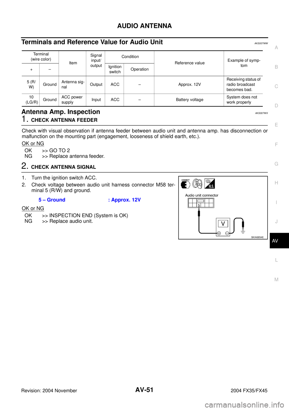
2. CHECK ANTENNA SIGNAL
1. Turn the ignition switch ACC.
2. Check voltage between audio unit harness connector M58 ter-
minal 5 (R/W) and ground.
OK or NG
OK >> INSPECTION END (System is OK)
NG >> Replace audio unit.
Terminal
(wire color)
ItemSignal
input/
outputCondition
Reference valueExample of symp-
tom
+–Ignition
switchOperation
5 (R/
W)GroundAntenna sig-
nalOutput ACC – Approx. 12VReceiving status of
radio broadcast
becomes bad.
10
(LG/R)GroundACC power
supplyInput ACC – Battery voltageSystem does not
work properly
5 – Ground : Approx. 12V
SKIA6854E
Page 646 of 4449

INTEGRATED DISPLAY SYSTEM
AV-55
C
D
E
F
G
H
I
J
L
MA
B
AV
Revision: 2004 November 2004 FX35/FX45
INTEGRATED DISPLAY SYSTEMPFP:28090
System DescriptionAKS00BO5
A/C AND AV SWITCH SYSTEM
Refer to Owner′s Manual for A/C and AV switch operating instructions.
Using the A/C and AV switch at the center of the instrument panel, the controls of the following systems are
centralized:
�Integrated display system (Drive computer, setting screen, etc.)
�Auto A/C system
�Audio system
PRECAUTION OF LCD MONITOR
�In order to use LED for backlight of a display, by in car temperature, brightness may change. In low tem-
perature, the refreshing rate of the picture also becomes low because of the low response of the LCD
monitor. When passenger room becomes warm, however, the LCD recovers the normal display.
�Backlight sometimes flickers or darkens according to the total consumption hours and the number of times
switched ON and OFF. In this case, display unit should be replaced. (Exchange only of backlight is impos-
sible.)
POWER SUPPLY AND GROUND
Power is supplied at all times
�through 15A fuse (No. 32, located in fuse and fusible link box)
�to display unit terminal 1, and
�to A/C and AV switch terminal 1.
When ignition switch is in ACC or ON position, power is supplied
�through 10A fuse [No. 6, located in fuse block (J/B)]
�to display unit terminal 2, and
�to A/C and AV switch terminal 2.
When ignition switch is in ON or START position, power is supplied
�through 10A fuse [No. 12, located in fuse block (J/B)]
�to display unit terminal 3.
Ground is supplied
�to display unit terminals 6 and 15, and
�to A/C and AV switch terminal 5
�through body grounds M35, M45 and M85.
Page 663 of 4449

AV-72
INTEGRATED DISPLAY SYSTEM
Revision: 2004 November 2004 FX35/FX45
Terminals and Reference Value for Display UnitAKS00BOD
Terminal No.
(Wire color)
ItemSignal
input/
outputCondition
VoltageExample of
symptom
+–Ignition
switchOperation
1 (W/L) GroundBattery power
supplyInput OFF - Battery voltageSystem does not
work properly.
2 (LG/R) GroundACC power
supplyInput ACC - Battery voltageSystem does not
work properly.
3 (G/R) Ground Ignition signal Input ON - Battery voltageA/C operation is
not possible.
Vehicle informa-
tion setting is not
possible.
4 (R/L) GroundIllumination
signalInput OFFLighting switch is
ON .Approx. 12VScreen does not
switch to night-
time mode after
the lighting switch
is turned ON. Llighting switch is
OFF.Approx. 0V
6 (B) Ground Ground - ON - Approx. 0V -
7 (R/G) GroundVehicle speed
signal (8-pulse)Input ONWhen vehicle
speed is approx.
40 km/h (25 MPH)Drive computer
item is not dis-
played correctly.
8 (LG) Ground Audio TX Output ONOperate audio
volume.Audio does not
operate properly.
9 - Shield ground - - - - -
10 (B/Y) Ground Audio RX Input ONOperate audio
volume.Audio does not
operate properly.
11 (B/R) GroundCommunica-
tion signal (+)Input/
outputON -System does not
work properly.
12 - Shield ground - - - - -
PKIA1935E
SKIA4402E
SKIA4403E
SKIA0175E
Page 664 of 4449

INTEGRATED DISPLAY SYSTEM
AV-73
C
D
E
F
G
H
I
J
L
MA
B
AV
Revision: 2004 November 2004 FX35/FX45
Terminals and Reference Value for A/C and AV SwitchAKS00BOE
13 (W/R) GroundCommunica-
tion signal (-)Input/
outputON -System does not
work properly.
14 (L) - CAN-H - - - - -
15 (B) - Shield ground - - - - -
16 (R) - CAN-L - - - - -Terminal No.
(Wire color)
ItemSignal
input/
outputCondition
Voltag eExample of
symptom
+–Ignition
switchOperation
SKIA0176E
Terminal No.
(Wire color)
ItemSignal
input/
outputCondition
Vo l ta g eExample of
symptom
+–Ignition
switchOperation
1 (W/L) GroundBattery power
suoplyInput OFF - Battery voltageSystem does not
work properly.
2 (LG/R) GroundACC power
supply Input ACC - Battery voltageSystem does not
work properly.
5 (B) Ground Ground - ON - Approx. 0V -
6 (B/R) GroundCommunica-
tion signal (+)Input/
outputON -System does not
work properly.
7 - Shield ground - - - - -
8 (W/R) GroundCommunica-
tion signal (-)Input/
outputON -System does not
work properly.
12 (R/G) GroundRemote con-
troller AInput ONPress MODE
switch. Approx. 0V
Audio steering
wheel switches
do not function. Press SEEK UP
switch.Approx. 1.7V
Press VOL UP
switch.Approx. 3.3V
Except for above Approx. 5V
SKIA0175E
SKIA0176E
Page 665 of 4449

AV-74
INTEGRATED DISPLAY SYSTEM
Revision: 2004 November 2004 FX35/FX45
On Board Self-Diagnosis FunctionAKS00BOF
DESCRIPTION
�Diagnosis function consists of the self-diagnosis mode performed automatically.
�Self-diagnosis mode checks for connections between the units constituting this system, analyzes each
individual unit at the same time, and displays the results on the LCD screen.
DIAGNOSIS ITEM
Self-Diagnosis ModeAKS00BOG
OPERATION PROCEDURES
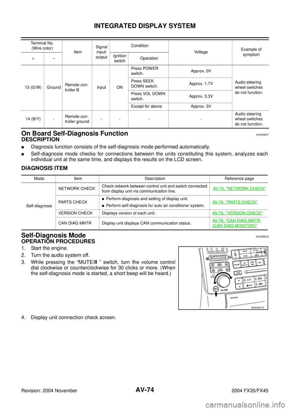
1. Start the engine.
2. Turn the audio system off.
3. While pressing the “MUTE/II ” switch, turn the volume control
dial clockwise or counterclockwise for 30 clicks or more. (When
the self-diagnosis mode is started, a short beep will be heard.)
4. Display unit connection check screen.
13 (G/W) GroundRemote con-
troller BInput ONPress POWER
switch.Approx. 0V
Audio steering
wheel switches
do not function. Press SEEK
DOWN switch.Approx. 1.7V
Press VOL DOWN
switch.Approx. 3.3V
Except for above Approx. 5V
14 (B/Y) -Remote con-
troller ground-- - -Audio steering
wheel switches
do not function. Terminal No.
(Wire color)
ItemSignal
input/
outputCondition
VoltageExample of
symptom
+–Ignition
switchOperation
Mode Item Description Reference page
Self-diagnosisNETWORK CHECKCheck network between control unit and switch connected
from display unit via communication line.AV-75, "
NETWORK CHECK"
PARTS CHECK�Perform diagnosis and setting of display unit.
�Perform self-diagnosis for auto air conditioner system.AV- 7 6 , "PARTS CHECK"
VERSION CHECK Displays version of each unit.AV- 7 6 , "VERSION CHECK"
CAN DIAG MNTR Display unit displays CAN communication status.AV- 7 6 , "CAN DIAG MNTR
(CAN DIAG MONITOR)"
SKIA4971E
Page 668 of 4449
INTEGRATED DISPLAY SYSTEM
AV-77
C
D
E
F
G
H
I
J
L
MA
B
AV
Revision: 2004 November 2004 FX35/FX45
A/C and AV Switch Self-Diagnosis FunctionAKS00BOH
It can check ON/OFF operation of each switch in the A/C and AV switch and diagnose the input signals to the
steering switch (audio).
STARTING THE SELF-DIAGNOSIS MODE
1. Turn ignition switch from OFF to ACC.
2. Within 10 seconds press and hold the switches “MUTE/II ” and
“PREV ” simultaneously for 3 seconds.
DIAGNOSIS FUNCTION
The following are checked:
�All the indicators (LED) in the A/C and AV switch.
�Continuity of the switches by sounding the buzzer when the A/C and AV switch is pressed.
�Continuity of harness between A/C and AV switch and steering switch (audio).
EXITING THE SELF-DIAGNOSIS MODE
�Turn ignition switch OFF. Then the self-diagnosis ends.
SKIA4972E
Page 669 of 4449

AV-78
INTEGRATED DISPLAY SYSTEM
Revision: 2004 November 2004 FX35/FX45
Trouble Diagnosis Chart by SymptomAKS00BOI
Symptom Check item
No screen is shown.
�Display unit power supply and ground circuit. Refer to AV- 7 9 , "Power Supply
and Ground Circuit Check for Display Unit" .
�Display unit
Screen does not switch to nighttime mode after the
lighting switch is turned ON.
�Illumination signal. Refer to AV-81, "Illumination Signal Inspection" .
�Display unit
TRIP and FUEL ECON screen do not appear.
�Ignition signal. Refer to AV- 8 2 , "Ignition Signal Inspection" .
�Display unit
�Trip odometer (DIST) is not added up.
�Average vehicle speed (AVG) is not displayed.
�Vehicle speed signal. Refer to AV- 8 0 , "Vehicle Speed Signal Inspection" .
�Display unit
Average fuel consumption (AVG) is not displayed.
�Vehicle speed signal. Refer to AV- 8 0 , "Vehicle Speed Signal Inspection" .
�CAN communication line. Refer to AV- 8 5 , "CAN Communication Line Inspec-
tion" .
�Display unit
Distance to empty (DTE) is not displayed.
�Check if speedometer operates. If it does not operate, go to DI-17, "Vehicle
Speed Signal Inspection" .
�Check if fuel gauge operates. If it does not operate, go to DI-20, "Fuel Level
Sensor Signal Inspection 1" .
�CAN communication line. Refer to DI-22, "Communication Line Inspection" .
�Display unit
Tire pressure is not displayed.
�Ignition signal. Refer to AV- 8 2 , "Ignition Signal Inspection" .
�Low tire pressure warning control unit. Refer to WT-17, "Self-Diagnosis" .
�CAN communication line. Refer to DI-22, "Communication Line Inspection" .
�Display unit
Door warning screen does not appear.
�Ignition signal. Refer to AV- 8 2 , "Ignition Signal Inspection" .
�Vehicle speed signal. Refer to AV- 8 0 , "Vehicle Speed Signal Inspection" .
�CAN communication line. Refer to AV- 8 5 , "CAN Communication Line Inspec-
tion" .
�Display unit
A/C and AV switch and all switch operation are not
possible.
(Do not start self-diagnosis.)Refer to AV-84, "
A/C and AV Switch Does Not Operate" .
Air conditioner operation is not possible.
�A/C and AV switch. Refer to AV-41, "A/C and AV Switch Inspection" .
�CAN communication line. Refer to AV- 8 5 , "CAN Communication Line Inspec-
tion" .
Page 670 of 4449

INTEGRATED DISPLAY SYSTEM
AV-79
C
D
E
F
G
H
I
J
L
MA
B
AV
Revision: 2004 November 2004 FX35/FX45
Power Supply and Ground Circuit Check for Display UnitAKS00BOJ
1. CHECK FUSE
Make sure that the following fuses in display unit are not blown.
OK or NG
OK >> GO TO 2.
NG >> If fuse is blown be sure to eliminate case of malfunction before installing new fuse. Refer to PG-3,
"POWER SUPPLY ROUTING CIRCUIT" .
2. CHECK POWER SUPPLY CIRCUIT
Check voltage between display unit harness connector terminals
and ground.
OK or NG
OK >> GO TO 3.
NG >> Repair harness or connector.
3. CHECK GROUND CIRCUIT
1. Turn ignition switch OFF.
2. Disconnect display unit connector.
3. Check continuity between display unit harness connector M62
terminals 6 (B), 15 (B) and ground.
OK or NG
OK >> INSPECTION END
NG >> Repair harness or connector.
Unit Signal Fuse No.
Display unitBattery power supply 32
Ignition switch ACC or ON 6
Terminals Ignition switch position
(+)
(–) OFF ACC ON
ConnectorTerminal
(Wire color)
M621 (W/L) GroundBattery
voltageBattery
voltageBattery
voltage
2 (LG/R) Ground 0VBattery
voltageBattery
voltage
SKIB0373E
6, 15 – ground : Continuity should exist.
SKIA4986E