Page 2804 of 4449
![INFINITI FX35 2004 Service Manual TIMING CHAIN
EM-79
[VQ35DE]
C
D
E
F
G
H
I
J
K
L
MA
EM
Revision: 2004 November 2004 FX35/FX45
19. Install front timing chain case as follows:
a. Apply liquid gasket to front timing chain case back side](/manual-img/42/57021/w960_57021-2803.png "INFINITI FX35 2004 Service Manual TIMING CHAIN
EM-79
[VQ35DE]
C
D
E
F
G
H
I
J
K
L
MA
EM
Revision: 2004 November 2004 FX35/FX45
19. Install front timing chain case as follows:
a. Apply liquid gasket to front timing chain case back side")
TIMING CHAIN
EM-79
[VQ35DE]
C
D
E
F
G
H
I
J
K
L
MA
EM
Revision: 2004 November 2004 FX35/FX45
19. Install front timing chain case as follows:
a. Apply liquid gasket to front timing chain case back side as
shown in the figure with tube presser [SST: WS39930000 ( – )].
Use Genuine RTV Silicone Sealant or equivalent. Refer to
GI-48, "
RECOMMENDED CHEMICAL PRODUCTS AND
SEALANTS".
b. Install dowel pin on rear timing chain case into dowel pin hole on
front timing chain case.
c. Tighten bolts to the specified torque in order as shown in the fig-
ure.
d. After tightening, retighten them to specified torque in numerical
order shown in figure.
20. After installing front timing chain case, check the surface height
difference between the following parts on the oil pan mounting
surface.
�If not within specification, repeat the installation procedure.
21. Install right and left intake valve timing control covers as follows:
a. Install seal rings in shaft grooves.
b. Apply liquid gasket to intake valve timing control covers as
shown in the figure with tube presser [SST: WS39930000 ( – )].
Use Genuine RTV Silicone Sealant or equivalent. Refer to
GI-48, "
RECOMMENDED CHEMICAL PRODUCTS AND
SEALANTS".
PBIC1133E
8 mm (0.31 in) dia. bolts : 1, 2
: 28.4 N·m (2.9 kg-m, 21 ft-lb)
6 mm (0.24 in) dia. bolts : Except the above
: 12.7 N·m (1.3 kg-m, 9 ft-lb)
KBIA1303E
Standard
Front timing chain case to rear timing chain case:
–0.14 to 0.14 mm (–0.005 to 0.0055 in)
SEM943G
SBIA0492E
Page 2805 of 4449
![INFINITI FX35 2004 Service Manual EM-80
[VQ35DE]
TIMING CHAIN
Revision: 2004 November 2004 FX35/FX45
c. Install collared O-ring in front cover engine oil hole (left and right
sides).
d. Being careful not to move seal ring from the ins](/manual-img/42/57021/w960_57021-2804.png "INFINITI FX35 2004 Service Manual EM-80
[VQ35DE]
TIMING CHAIN
Revision: 2004 November 2004 FX35/FX45
c. Install collared O-ring in front cover engine oil hole (left and right
sides).
d. Being careful not to move seal ring from the ins")
EM-80
[VQ35DE]
TIMING CHAIN
Revision: 2004 November 2004 FX35/FX45
c. Install collared O-ring in front cover engine oil hole (left and right
sides).
d. Being careful not to move seal ring from the installation groove,
align dowel pins on chain case with the holes to install intake
valve timing control covers.
e. Tighten bolts in the numerical order as shown in the figure.
22. Install crankshaft pulley as follows:
a. Fix crankshaft using ring gear stopper [SST: KV10117700 (J-44716)].
b. Install crankshaft pulley, taking care not to damage front oil seal.
�When press-fitting crankshaft pulley with a plastic hammer, tap on its center portion (not circumfer-
ence).
c. Tighten bolt.
d. Put a paint mark on crankshaft pulley aligning with angle mark
on crankshaft pulley bolt. Then, further retighten bolt by “60”
degrees (equivalent to one graduation).
23. Rotate crankshaft pulley in normal direction (clockwise when viewed from front) to confirm it turns
smoothly.
24. For the following operations, perform steps in the reverse order of removal.
NOTE:
If hydraulic pressure inside chain tensioner drops after removal/installation, slack in guide may generate a
pounding noise during and just after engine start. However, this does not indicate an unusualness. Noise
will stop after hydraulic pressure rises.
INSPECTION AFTER INSTALLATION
�Before starting engine, check the levels of engine coolant, lubrications and working fluid. If less than
required quantity, fill to the specified level.
�Run engine to check for unusual noise and vibration.
PBIC2045E
PBIC0918E
: 44.1 N·m (4.5 kg-m, 33 ft-lb)
SEM751G
Page 2806 of 4449
TIMING CHAIN
EM-81
[VQ35DE]
C
D
E
F
G
H
I
J
K
L
MA
EM
Revision: 2004 November 2004 FX35/FX45
�Warm up engine thoroughly to make sure there is no leakage of engine coolant, engine oil and working
fluid, fuel and exhaust gas.
�Bleed air from passages in pipes and tubes of applicable lines, such as in cooling system.
�After cooling down engine, again check amounts of engine coolant, engine oil and working fluid. Refill to
specified level, if necessary.
Summary of the inspection items:
Item Before starting engine Engine running After engine stopped
Engine coolant Level Leakage Level
Engine oil Level Leakage Level
Working fluid Level Leakage Level
Page 2807 of 4449
EM-82
[VQ35DE]
CAMSHAFT
Revision: 2004 November 2004 FX35/FX45
CAMSHAFTPFP:13001
Removal and InstallationABS00FPH
1.Intake valve timing control solenoid
valve2. Gasket 3. Camshaft bracket (No. 2 to No. 4)
4. Camshaft (EXH) 5. Camshaft (INT) 6. Camshaft bracket (No. 1)
7. Dowel pin 8. Valve lifter 9. O-ring
10. Chain tensioner 11. Spring 12. Plunger
13. Cylinder head (right bank) 14. Cylinder head (left bank) 15.Camshaft position sensor (PHASE)
(right bank)
16.Camshaft position sensor (PHASE)
(left bank)
SBIA0576E
Page 2808 of 4449
![INFINITI FX35 2004 Service Manual CAMSHAFT
EM-83
[VQ35DE]
C
D
E
F
G
H
I
J
K
L
MA
EM
Revision: 2004 November 2004 FX35/FX45
REMOVAL
1. Remove front timing chain case, camshaft sprocket, timing chain and rear timing chain case. Refer to](/manual-img/42/57021/w960_57021-2807.png "INFINITI FX35 2004 Service Manual CAMSHAFT
EM-83
[VQ35DE]
C
D
E
F
G
H
I
J
K
L
MA
EM
Revision: 2004 November 2004 FX35/FX45
REMOVAL
1. Remove front timing chain case, camshaft sprocket, timing chain and rear timing chain case. Refer to")
CAMSHAFT
EM-83
[VQ35DE]
C
D
E
F
G
H
I
J
K
L
MA
EM
Revision: 2004 November 2004 FX35/FX45
REMOVAL
1. Remove front timing chain case, camshaft sprocket, timing chain and rear timing chain case. Refer to EM-
63, "TIMING CHAIN" .
2. If necessary, remove camshaft position sensor (PHASE) (right
and left banks) from cylinder head back side.
CAUTION:
�Handle carefully to avoid dropping and shocks.
�Do not disassemble.
�Do not allow metal powder to adhere to magnetic part at
sensor tip.
�Do not place sensors in a location where they are
exposed to magnetism.
3. Remove intake valve timing control solenoid valve from No.1
camshaft bracket.
4. Remove intake and exhaust camshaft brackets.
�Mark camshafts, camshaft brackets, and bolts so they are
placed in the same position and direction for installation.
�Equally loosen camshaft bracket bolts in several steps in the
reverse order as shown in the figure.
5. Remove camshaft.
6. Remove valve lifter.
�Identify installation positions, and store them without mixing them up.
KBIA1046E
SEM443GA
PBIC2050E
Page 2809 of 4449
![INFINITI FX35 2004 Service Manual EM-84
[VQ35DE]
CAMSHAFT
Revision: 2004 November 2004 FX35/FX45
7. Remove secondary timing chain tensioner from cylinder head.
�Remove chain tensioner with its stopper pin attached.
NOTE:
Stopper pin w](/manual-img/42/57021/w960_57021-2808.png "INFINITI FX35 2004 Service Manual EM-84
[VQ35DE]
CAMSHAFT
Revision: 2004 November 2004 FX35/FX45
7. Remove secondary timing chain tensioner from cylinder head.
�Remove chain tensioner with its stopper pin attached.
NOTE:
Stopper pin w")
EM-84
[VQ35DE]
CAMSHAFT
Revision: 2004 November 2004 FX35/FX45
7. Remove secondary timing chain tensioner from cylinder head.
�Remove chain tensioner with its stopper pin attached.
NOTE:
Stopper pin was attached when secondary timing chain was
removed.
INSPECTION AFTER REMOVAL
Camshaft Runout
1. Put V block on precise flat bed, and support No. 2 and No. 4
journal of camshaft.
CAUTION:
Do not support journal No. 1 (on the side of camshaft
sprocket) because it has a different diameter from the other
three locations.
2. Set dial gauge vertically to No. 3 journal.
3. Turn camshaft to one direction with hands, and measure cam-
shaft runout on dial gauge. (Total indicator reading)
4. If it exceeds the standard, replace camshaft.
Camshaft Cam Height
1. Measure camshaft cam height.
2. If wear is beyond the limit, replace camshaft.
Camshaft Journal Oil Clearance
Outer Diameter of Camshaft Journal
Measure outer diameter of camshaft journal.
Inner Diameter of Camshaft Bracket
�Tighten camshaft bracket bolt with specified torque. Refer to EM-87, "INSTALLATION" .
SBIA0499E
Standard : Less than 0.05 mm (0.0020 in)PBIC0929E
Standard cam height (intake and exhaust)
: 44.865 - 45.055 mm (1.7663 - 1.7738 in)
Cam wear limit
: 0.2 mm (0.008 in)
EMQ0072D
Standard outer diameter:
No. 1: 25.935 - 25.955 mm (1.0211 - 1.0218 in)
No. 2, 3, 4: 23.445 - 23.465 mm (0.9230 - 0.9238 in)
PBIC0040E
Page 2814 of 4449
![INFINITI FX35 2004 Service Manual CAMSHAFT
EM-89
[VQ35DE]
C
D
E
F
G
H
I
J
K
L
MA
EM
Revision: 2004 November 2004 FX35/FX45
5. Tighten camshaft brackets in the following steps, in numerical
order as shown in the figure.
a. Tighten No.](/manual-img/42/57021/w960_57021-2813.png "INFINITI FX35 2004 Service Manual CAMSHAFT
EM-89
[VQ35DE]
C
D
E
F
G
H
I
J
K
L
MA
EM
Revision: 2004 November 2004 FX35/FX45
5. Tighten camshaft brackets in the following steps, in numerical
order as shown in the figure.
a. Tighten No.")
CAMSHAFT
EM-89
[VQ35DE]
C
D
E
F
G
H
I
J
K
L
MA
EM
Revision: 2004 November 2004 FX35/FX45
5. Tighten camshaft brackets in the following steps, in numerical
order as shown in the figure.
a. Tighten No. 7 to 10, then tighten No. 1 to 6 in order as shown.
b. Tighten all bolts in numerical order as shown.
c. Tighten all bolts in the numerical order as shown.
CAUTION:
After tightening mounting bolts of No. 1 camshaft brackets
(No. 1), be sure to wipe off excessive liquid gasket from the
parts list below.
�Mating surface of rocker cover
�Mating surface of rear timing chain case
6. Measure difference in levels between front end faces of No. 1
camshaft bracket and cylinder head.
�If measurement is outside the specified range, re-install cam-
shaft and camshaft bracket.
7. Inspect and adjust valve clearance. Refer to EM-89, "
Valve Clearance" .
8. Install in the reverse order of removal after this step.
Va l v e C l e a r a n c eABS004XG
INSPECTION
Perform inspection as follows after removal, installation or replace-
ment of camshaft or valve-related parts, or if there is unusual engine
conditions regarding valve clearance.
1. Remove right and left rocker covers with power tool. Refer to EM-51, "
ROCKER COVER" .
2. Measure valve clearance as below:
a. Set No. 1 cylinder at TDC of its compression stroke. : 1.96 N·m (0.20 kg-m, 1 ft-lb)
: 5.88 N·m (0.60 kg-m, 4 ft-lb)
: 10.4 N·m (1.1 kg-m, 8 ft-lb)
PBIC2050E
Standard : –0.14 to 0.14 mm (–0.0055 to 0.0055 in)
EMQ0044D
SEM713A
Page 2815 of 4449
EM-90
[VQ35DE]
CAMSHAFT
Revision: 2004 November 2004 FX35/FX45
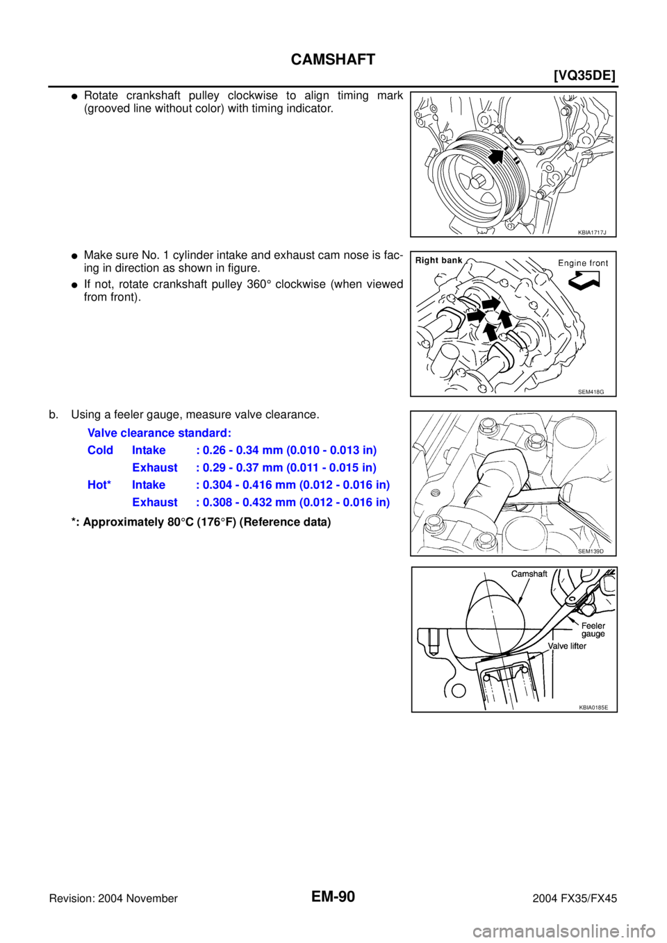
�Rotate crankshaft pulley clockwise to align timing mark
(grooved line without color) with timing indicator.
�Make sure No. 1 cylinder intake and exhaust cam nose is fac-
ing in direction as shown in figure.
�If not, rotate crankshaft pulley 360° clockwise (when viewed
from front).
b. Using a feeler gauge, measure valve clearance.
*: Approximately 80°C (176°F) (Reference data)
KBIA1717J
SEM418G
Valve clearance standard:
Cold Intake : 0.26 - 0.34 mm (0.010 - 0.013 in)
Exhaust : 0.29 - 0.37 mm (0.011 - 0.015 in)
Hot* Intake : 0.304 - 0.416 mm (0.012 - 0.016 in)
Exhaust : 0.308 - 0.432 mm (0.012 - 0.016 in)
SEM139D
KBIA0185E

![INFINITI FX35 2004 Service Manual EM-82
[VQ35DE]
CAMSHAFT
Revision: 2004 November 2004 FX35/FX45
CAMSHAFTPFP:13001
Removal and InstallationABS00FPH
1.Intake valve timing control solenoid
valve2. Gasket 3. Camshaft bracket (No. 2 to N](/manual-img/42/57021/w960_57021-2806.png "INFINITI FX35 2004 Service Manual EM-82
[VQ35DE]
CAMSHAFT
Revision: 2004 November 2004 FX35/FX45
CAMSHAFTPFP:13001
Removal and InstallationABS00FPH
1.Intake valve timing control solenoid
valve2. Gasket 3. Camshaft bracket (No. 2 to N")